1
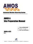
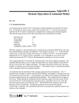
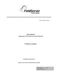
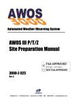
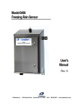
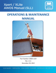
Automated Weather Observing System
AWOS Net
User’s Manual
2210-001
Rev. D
All Weather Inc. • 1165 National Drive • Sacramento, CA 95834 • USA • 800.824.5873 • www.allweatherinc.com
Copyright © 2010, All Weather, Inc.
All Rights Reserved. The information contained herein is proprietary and is provided solely for the purpose of allowing customers to operate and/or service All Weather, Inc. manufactured equipment and is
not to be released, reproduced, or used for any other purpose without written permission of All
Weather, Inc.
Throughout this manual, trademarked names might be used. Rather than put a trademark (™) symbol in
every occurrence of a trademarked name, we state herein that we are using the names only in an editorial
fashion and to the benefit of the trademark owner, and with no intention of infringement. All Weather,
Inc. and the All Weather, Inc. logo are trademarks of All Weather, Inc.
Disclaimer
The information and specifications described in this manual are subject to change without notice.
Latest Manual Version
For the latest version of this manual, see the Product Manuals page under Reference on our web site at
www.allweatherinc.com/.
All Weather, Inc.
1165 National Drive
Sacramento, CA 95834
Tel.: (916) 928-1000
Fax: (916) 928-1165
Contact Customer Service
•
Phone support is available from 8:00am - 4:30pm PT, Monday through Friday. Call 916-928-1000
and ask for “Service.”
•
Online support is available by filling out a request at www.allweatherinc.com/customer/support.html
•
E-mail your support request to [email protected]
AWOS NET USER'S MANUAL
Table of Contents
1. SYSTEM DESCRIPTION.................................................................................................................................................................... 1
1.1
AWOS Installations ............................................................................................................................................................... 2
2. INSTALLATION.................................................................................................................................................................................. 4
2.1
AWOS Net Controller Installation .......................................................................................................................................... 4
2.2
Communication Packages .................................................................................................................................................... 5
2.3
CDP Connection Installation ................................................................................................................................................. 6
2.4
Flat Panel Display Installation ............................................................................................................................................... 7
2.5
Printer Installation (optional) ................................................................................................................................................. 8
3. OPERATION....................................................................................................................................................................................... 9
3.1
Data Display .......................................................................................................................................................................... 9
3.2
Configuration....................................................................................................................................................................... 12
3.3
AWOS Net Data Handling ................................................................................................................................................... 13
4. MAINTENANCE ............................................................................................................................................................................... 14
5. WARRANTY ..................................................................................................................................................................................... 15
1
Chapter
AWOS Net is FAA certified for land use only. It is not certified for use in aircraft.
SYSTEM DESCRIPTION
AWOS Net is a data dissemination and display network that leverages the capability of All
Weather, Inc.'s Automated Weather Observing System (AWOS) to broadcast current weather
data to a flexible network of display stations. Using AWOS Net, preprocessed data from the
FAA-certified AWOS is available to local and remote displays.
AWOS Net consists of an AWOS Net Controller and Communication Interface connected to an
AWOS, along with one or more remote displays.
Figure 1. AWOS Net Architecture
1
SYSTEM
AWOS NET USER'S MANUAL
DESCRIPTION
The AWOS Net is only capable of receiving data from the AWOS system. It cannot send any
information to the AWOS and therefore cannot distort or otherwise alter the AWOS data.
There are three communication options for the AWOS Net. The 2210 is the standard AWOS Net
with RS-232 communication to the AWOS. The 2210-U has a UHF radio for communication to
the AWOS when the AWOS Net is not desired or able to be near the AWOS. The 2210-R has RS485 communication to the AWOS for hardwired connections to the AWOS greater than 500 feet.
The 2210 is provided with a 17" flat panel LCD display. The 2211 is an AWOS Net Controller
only, with no monitor or communication package. This allows section of any larger monitor size
(19", 22", or 24") or no monitor at all and the selection of the desired communication package
(RS-232, RS-485, or UHF radio).
1.1 AWOS Installations
The AWOS sensors measure an array of parameters under control of the Data Collection
Platform (DCP). The DCP transmits the collected data to the Central Data Platform (CDP) for
processing via an RS-232, RS-485, or UHF radio link. The standard 2210 communicates with the
CDP via the RS-232 link. The 2210-U communicates utilizing a UHF radio link on the same
frequency as the CDP-to-DCP communication link. The 2210-R communicates with the CDP
utilizing a RS-485 data link. Both the standard 2210 and the 2210-R can still be used with an
AWOS using a UHF data link between the CDP and DCP if the AWOS Net Controller is hardwired to the CDP.
At a minimum of once per minute, the CDP broadcasts its latest data for all monitored
parameters. The AWOS Net Controller acquires the data via the AWOS communications line
from the CDP's Peripheral Interface, then encapsulates it and broadcasts it via Ethernet
connection to all active remote connections. This permits AWOS Net Remote Displays to
receive current data within milliseconds of the CDP broadcasting the update. To ensure the
reliability of the data, all communications are validated for timeliness and correctness before
display to the user.
The remote displays mirror the data displayed at the CDP following processing and application
of the AWOS algorithms. Remote users can also view the weather data in a standard web
browser via internet or local network connections.
2
SYSTEM
AWOS NET USER'S MANUAL
DESCRIPTION
3
2
Chapter
INSTALLATION
2.1 AWOS Net Controller Installation
Figure 2 shows the back panel connections for the AWOS Net Controller. The connections used
with the standard AWOS Net are:
•
Power (green snap-on screw terminal)
•
Data Communications (green-blue 9- pin serial connector)
•
Remote Display (blue 15-pin connector)
•
Printer - optional (purple 25-pin connector)
Figure 2. AWOS Net Controller Back Panel Connections
4
AWOS NET USER'S MANUAL
INSTALLATION
2.2 Communication Packages
There are three different communication packages for the AWOS Net. They are RS-232, RS485, and UHF radio. The RS-232 communication package connects to the AWOS Net Controller
differently than the RS-485 and UHF radio packages.
2.2.1 RS-232 Communication Package
The RS-232 communication package should be used when the AWOS Net will be within 500
feet of the AWOS CDP and a CAT5e cable (not supplied by AWI unless requested) can be used
to connect the two together. The RS-232 communication package consists of a RS-232 Y-cable
for listening to the CDP communication and a custom DB9 to RJ-45 adapter securely mounted to
the data communications serial connector on the AWOS Net Controller. The CAT5e cable, that
is run between the AWOS Net and CDP, is
connected to RJ-45 adapter and not the Ethernet
jack (the RJ-45 connector with the green and
yellow LEDs next to it).
The RS-232 communication package also
includes the power supply for the AWOS Net
controller. This consists of a power cable
(M492186) and power adapter (M406117-00) for
connecting to AC power. The power cable comes
pre-wired to the controller. Simply plug the power
cable into a suitable AC outlet.
2.2.2 RS-485 Communication Package
The RS-485 communication package should be used when the AWOS Net will be more than 500
feet from the AWOS CDP and a hard-wired connection is desired. The RS-485 communication
package is contained in one enclosure. The communication interface connects to the AWOS Net
Controller with a 9 pin serial connector (for RS-232 communication) and green plug in terminal
block (to supply power to the AWOS Net Controller).
5
AWOS NET USER'S MANUAL
INSTALLATION
2.2.3 UHF Radio Communication Package
The UHF radio communication package should be used when the CDP-to-DCP communication
link uses UHF radios and the AWOS Net will not be physically connected to the CDP. The UHF
antenna for the AWOS Net must still have line-of-sight with the CDP antenna in order to receive
the data from the CDP. The UHF radio communication package is contained in one enclosure
and connects to the AWOS Net Controller in the same fashion as the RS-485 interface.
2.3 CDP Connection Installation
2.3.1 CDP Communications Link
A serial link between the AWOS Net Controller and the AWOS Peripheral Interface enables
AWOS Net to communicate with the AWOS. This serial link can be an RS-232, RS-485, or UHF
radio communication link. The Communication Interface houses the appropriate hardware for the
desired communication link for RS-485 and UHF radio communication packages.
2.3.2 RS-232 Communications
The cabling for RS-232 communication consists of a Y-cable and a standard CAT5e patch cord
(not provided). The female 9-pin serial connector should be connected to COM1 on the back of
the CDP. The male 9-pin serial connector should be connected to the female connector of the
cable going to the Peripheral Interface. This allows the AWOS Net to listen to the CDP output
and still keep the connection to the Peripheral Interface. The standard CAT5e patch cord can
then be connected to the RJ-45 jack at the end of the Y-cable.
2.3.3 RS-485 Communications
An RS485-to-RS232 converter is mounted in the Communication Interface and pre-wired at the
factory. The CAT5e connection cable should already be mounted into the Peripheral Interface if
the AWOS Net is purchased with the system. If the AWOS Net is added later, this cable will be
provided as part of the AWOS Net and will need to be installed into the Peripheral Interface
using the following steps.
1. Remove the cover from the Peripheral Interface to expose the PCB. Locate terminal
block J2.
2. Feed the cable through the large hole with
the other cables. The RJ-45 jack should
remain on the outside of the enclosure.
3. The serial cable consists of four wires.
Two of the wires (RS485- and RS485+)
are terminated with ferrules. The other
two wires are terminated with a lug; this is
the ground connection.
6
AWOS NET USER'S MANUAL
INSTALLATION
4. Connect the blue wire to pin 5 (RS485-) on terminal block J2.
5. Connect the blue/white wire to pin 6 (RS485+) on terminal block J2.
6. Connect the ground wire to one of the PC board's corner mounting screws by loosening
the screw and inserting the cable's lug between the PC board and screw, then tightening
the screw.
7. Replace the cover on the Peripheral Interface.
Once the connection cable is attached to the peripheral interface, the connection between the
CDP and the AWOS Net communication interface can be completed with a standard CAT5e
patch cable (not provided by AWI). This cable connects to the coupler on the end of the cable
installed into the Peripheral Interface with the other end connecting to the coupler on the end of
the cable at the AWOS Net communication interface.
2.3.4 UHF Communications
There are times when the AWOS Net Controller cannot be hardwired to the AWOS CDP. This
may be to use the display ability of the AWOS Net at a different building or to bring the AWOS
Net Controller to an Ethernet connection. The only additional connection that the 2210-U
requires is the connection of the BNC connector on the Communication Interface connected to
the UHF antenna. There is no wired connection to the CDP. The antenna and cable for the
antenna are not included in the UHF radio package and can be supplied by AWI at additional
cost.
2.4 Flat Panel Display Installation
1. Connect the display's data cable to the
blue Remote Display connector on the
AWOS Net Controller's back panel
and tighten the thumbscrews to secure
the cable to the connector.
2. Plug the display's power cord into a
suitable AC outlet.
7
AWOS NET USER'S MANUAL
INSTALLATION
2.5 Printer Installation (optional)
When an optional printer is installed, connect it as follows.
1. Connect the printer cable to the purple
Printer connector on the AWOS Net
Controller's back panel (see Figure 2).
2. Plug the printer's power cord into a
suitable AC outlet.
8
3
Chapter
OPERATION
3.1 Data Display
The Remote Displays present weather data in a combination of text and graphic formats, as
shown in Figure 3. The paragraphs below give a brief explanation of the data fields. For a
complete description of the algorithms, refer to the Model 2090 CDP User's Manual. Missing
data is designated with the four hash marks as shown for Present Weather in Figure 3. If the data
field is sent by the CDP but the CDP reports it as invalid, the data field will be blank.
3.1.1 Site Description Fields
There are three description fields in the display. The airport name is set in the AWOS Net
configuration. The airport name is shown as “Roberts Field” in Figure 3. The site identifier is a
three or four digit identifier for the site. This field is obtained from the AWOS CDP and shown
as “KMHV” in Figure 3. The runway description is shown directly above the wind dial on the
display. This is set in the AWOS Net configuration. If the data is for an actual runway, then the
runway end numbers can displayed, such as “12/30” as shown in the Winds section. If the data is
not for a runway, any text string can be used as shown as “Heli Pad” in Figure 3.
Figure 3. Remote Display Screen Example
9
AWOS NET USER'S MANUAL
OPERATION
3.1.2 Pressure
The pressure is displayed in inches of mercury (inHg) and can be configured to display in
hectopascals (hPa), which is also equivalent to millibars (mb). Density Altitude is calculated by
the CDP and reported in feet. Density altitude is not reported if it is less than 1000’ above the
field elevation.
3.1.3 Winds
Instantaneous (current) and 2-minute average (2 min) values for wind speed and direction are
shown in the Winds section. In addition to the numeric display of wind data, wind data is also
presented on the graphic dial in the middle of the text display. The values shown on the dials are
instantaneous (5-second) values. The outer ring on the wind direction dial shows a dark band for
variable wind. Variable wind is calculated using a 10-minute average of wind direction readings.
The wind speed is displayed into knots. If a valid runway is entered into the configuration, a
runway image will be imposed into the wind dial with the correct orientation for the runway.
Wind speed units default to knots (kt). This can be changed to miles per hour (MPH), kilometers
per hour (KPH), or meters per second (m/s) in the AWOS Net configuration. Wind direction is
displayed in degrees.
3.1.4 Temperature
Instantaneous and 10-minute average values for air temperature and dew point temperature,
along with current values for relative humidity (RH) are shown in the Temperature section.
Temperature and dew point are displayed in Celsius and relative humidity is display in percent.
Temperature can be displayed in Fahrenheit units with a change in the AWOS Net configuration.
10
AWOS NET USER'S MANUAL
OPERATION
3.1.5 Precipitation
Rainfall accumulation is reported by the Rain Gauge in 0.01” increments. The value is updated
every five seconds and is reset to 0 at midnight. If the system has a Present Weather sensor, this
value could be from that sensor rather than a Rain Gauge. If the system has both sensors, it will
be data from the Rain Gauge. With either sensor, the precipitation is displayed in inches.
3.1.6 Visibility
Visibility is a ten-minute average calculated each minute from sensor readings taken at tensecond intervals. The Visibility Sensor also performs self-checks of communications, window
condition, and a number of operational functions, and reports any errors in its status words.
Visibility is displayed in miles by default and can be set in meters with a change in the AWOS
Net configuration.
3.1.7 Clouds
A laser ceilometer measures sky condition and cloud height, reporting both the type of cloud
cover and the height of detected clouds. The type of cloud cover is represented by the following
codes:
FEW—few (≥6% to 24% sky cover)
SCT—scattered (≥25% to 49% sky cover)
BKN—broken (≥50% to 87% sky cover)
OVC—overcast (>87% sky cover)
VV00n—indefinite ceiling (haze or fog)
Cloud height is shown in hundreds of feet (12,000 feet, for instance, is represented by “120”).
Cloud height data is updated every minute based on a 30-minute sliding window.
3.1.8 Present Weather
Data from the Present Weather sensor is weighted over a ten-minute period by the CDP and is
updated every one minute. Data from the Lightning sensor will also be displayed with the
Present Weather sensor data. If there is a thunderstorm at the airport, the lightning data will
override the present weather data.
3.1.9 METAR
The METAR window shows the most recent METAR report generated by the AWOS.
3.1.9.1 Disclaimer
If the AWOS Net is connected to the Internet, the data displayed can be corrupted by an outside
source. This is why the AWOS Net has no physical communication path back to the AWOS
CDP and can in no way affect the AWOS system. A disclaimer is displayed at the bottom of the
screen warning that the data displayed is for informational purposes only and must not be used
for flight planning or operations. In the FAA disclaimer section, the phone number for the
11
AWOS NET USER'S MANUAL
OPERATION
AWOS system can be displayed, if desired. If there is no phone number stored in the AWOS Net
configuration, the “For official data…” sentence will not be displayed.
3.2 Configuration
Several of the fields on the display are configurable. The configuration is embedded in XML.
Configuration changes should be performed by AWI trained personnel only as XML errors can
prevent the AWOS Net from proper operation. There are also configuration options that can be
made in the XML for the network configuration.
3.2.1 Configuration File – host.dat
There are two host.dat files stored on the AWOS Net. One is located in the “/var/www/html/”
directory. This host.dat file holds the configuration for the web server output. The other host.dat
file is located in the “/home/awi/” directory. This host.dat file holds the configuration for the
local display. Except for the network fields, these two files will usually be the same. Any nonnetwork related changes made in one host.dat file must be made in the other host.dat file.
3.2.1.1 Site Description
The site name is set in the host.dat files. The name that should be displayed on the screen must
be in the “airportName” line of the host.dat files. A runway representation is available for the
wind dial. This is turned on by placing a runway number in the “runwayA” line in the host.dat
files. The number entered will determine the orientation and numbers of the runway displayed on
the wind dial. If a text value or no value is on this line, the runway overlay will not be displayed.
There is also a label available that will be displayed over the wind dial. This can be a text
description of any kind and is for display purposes only.
3.2.1.2 Sensor On/Off Control
There are four display values that can be turned off if the sensor is not a part of the AWOS
system at the site. The four display values that can be turned off are: Clouds, Visibility,
Precipitation, and Present Weather. When a display value is turned off, the title and data text is
changed to a dark gray color. Sensors are turned off by changing the fields in the host.dat file
from true to false. The four sensor fields are listed in the host.dat file as ceilometer, vis, rain, and
pwx respectively.
3.2.1.3 Unit of Measure
There are four parameters that can have their default units of measure changed. These are
changed by editing the proper parameter in the host.dat files.
Ø The temperature unit of measure is changed by editing the “temperatureUnits” line. This
should be set for “C” or “F” depending on Celsius or Fahrenheit units for temperature.
Ø The pressure unit of measure is changed by editing the “pressureUnits” line. This should
be set to “inHg” for inches of Mercury or “hPa” for hectopascals (millibars).
12
AWOS NET USER'S MANUAL
OPERATION
Ø Wind speed units of measure are changed by editing the “wind SpeedUnits” line. This
should be set to “knots”, “mph” (miles per hour), “kph” (kilometers per hour), or “mps”
(meters per second)
Ø Visibility units are changed by editing the “visibilityUnits” line. This should be set to
“miles” or “meters”.
3.2.1.4 Network Configuration
The AWOS Net must be configured with a static IP address in order to communicate with any
other computers on the network or over the internet. If the AWOS Net is operating as a remote
display only, and not as a Web server, this is not necessary. The “host” line in the host.dat file in
the “/var/www/html/” directory must be changed to the static IP address for the AWOS Net for
data to be sent to other computers on the network or internet. The AWOS Net uses ports 80,
8080, and 8887 for communication to the other computers. If any of these ports are not available,
the AWOS Net configuration must be changed for the web server operation to work properly.
Contact Customer Service for details about changing these ports in the AWOS Net configuration.
3.2.1.5 Mouse Cursor
The AWOS Net is for display purposes only and has no user interaction. Therefore a mouse is
not required (or provided). The mouse cursor can be visible or hidden. The “mouseHide” line in
the host.dat file controls the visibility of the cursor. If this line is set to “true”, the mouse cursor
will be hidden.
3.3 AWOS Net Data Handling
When an AWOS Net receives a data packet, it verifies its integrity based on an embedded CRC
checksum. If there is a mismatch, the entire message is considered to be corrupted, and is
discarded. In this case, the AWOS Net will retain previously received values (if there are any)
until they expire. In other words, receipt of a corrupted data packet does not, in itself, invalidate
any AWOS Net data.
METAR data are retained for 12 minutes, and all other fields are retained for 2 minutes. Unlike
the other observations, METAR data are generated every 5 minutes (or less often), and METAR
data include a timestamp.
13
4
Chapter
MAINTENANCE
The AWOS Net Controller and Remote Displays require no regular maintenance. For AWOS
system maintenance, refer to the appropriate system manuals and individual sensor manuals.
14
5
Chapter
WARRANTY
Unless specified otherwise, All Weather Inc. (the Company) warrants its products to be free from
defects in material and workmanship under normal use and service for one year from date of
shipment, subject to the following conditions:
(a) The obligation of the Company under this warranty is limited to repairing or replacing
items or parts which have been returned to the Company and which upon examination are
disclosed, to the Company’s satisfaction, to have been defective in material or
workmanship at time of manufacture.
(b) The claimant shall pay the cost of shipping any part or instrument to the Company. If the
Company determines the part to be defective in material or workmanship, the Company
shall prepay the cost of shipping the repaired instrument to the claimant. Under no
circumstances will the Company reimburse claimant for cost incurred in removing and/or
reinstalling replacement parts.
(c) This warranty shall not apply to any Company products which have been subjected to
misuse, negligence or accident.
(d) This warranty and the Company’s obligation thereunder is in lieu of all other warranties,
express or implied, including warranties of merchantability and fitness for a particular
purpose, consequential damages and all other obligations or liabilities.
No other person or organization is authorized to give any other warranty or to assume any
additional obligation on the Company’s behalf, unless made in writing and signed by an
authorized officer of the Company.
15
All Weather Inc.
1165 National Drive
Sacramento, CA 95834
Fax: 916.928.1165
Phone: 916.928.1000
Toll Free: 800.824.5873
www.allweatherinc.com
2210-001
Revision D
October, 2010