1
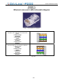
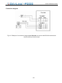
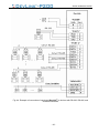
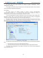
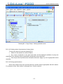
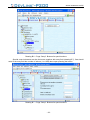
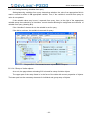
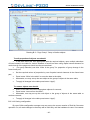
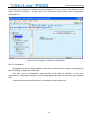
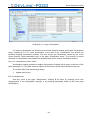
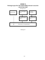
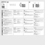
APPROVED JAYAK.420000.001-20RE-LU RCP Code 42 5200 PROTOCOL CONVERTER User's Manual JAYAK.420000.001-20 RE 49 sheets Penza, 2011 -1- JAYAK.420000.001-20 RE This manual is the official documentation of SPC KRUG Ltd © SPC KRUG Ltd, 2011 All rights reserved. Reference to SPC KRUG Ltd is obligatory for reprint. SPC KRUG Ltd is the owner of copyright for design of DevLink® series as a whole, for original technical solutions used in this product and also for built-in system software. The manufacturer reserves the right to amend the design and software to improve the product features. Please, refer your questions concerning usage and also requests for purchase of DevLink® series products to: SCIENTIFIC and PRODUCTION COMPANY (SPC) «KRUG» 1 Titova Street, Penza 440028, Russia Phone +7 (8412) 49-97-75, 55-64-97, 49-94-14, 48-34-80 Fax: +7 (8412) 55-64-96 E-mail: [email protected] http:// www.krug2000.ru Contact SPC KRUG technical support at e-mail: [email protected] - 2 ‐ JAYAK.420000.001-20 RE CONTENTS Page INTRODUCTION____________________________________________________________ 5 LIST OF ABBREVIATIONS ___________________________________________________ 6 1 DEVICE APPLICATION ___________________________________________________ 7 2 TECHNICAL CHARACTERISTICS __________________________________________ 8 2.1 Overall dimensions __________________________________________________ 8 2.2 Processing core parameters __________________________________________ 8 2.3 Power supply parameters _____________________________________________ 8 2.4 Interface parameters _________________________________________________ 8 2.5 Environment requirements ____________________________________________ 8 2.6 Environment mechanical stability ______________________________________ 8 2.7 Safety _____________________________________________________________ 9 2.8 Reliability __________________________________________________________ 9 3 DELIVERY SET ________________________________________________________ 10 4 DESIGN AND OPERATION _______________________________________________ 11 4.1 Interfaces _________________________________________________________ 11 4.2 Device design and operating principle _________________________________ 11 4.2.1 General description ________________________________________________ 11 4.2.2 Single-board version of DevLink®-P200 ________________________________ 12 4.2.3 Double-board version of DevLink®-P200 _______________________________ 18 4.3 Operating modes ___________________________________________________ 22 5 INTERACTION WITH OTHER DEVICES_____________________________________ 22 6 MEASURING DEVICES AND ACCESSORIES ________________________________ 23 7 MARKING AND SEALING ________________________________________________ 23 8 PACKAGE ____________________________________________________________ 23 9 INTENDED USAGE _____________________________________________________ 23 9.1 Operating restrictions _______________________________________________ 23 9.2 Preparation for usage _______________________________________________ 23 9.3 Unpacking ________________________________________________________ 24 9.4 The product external inspection range and order ________________________ 24 9.5 Installation ________________________________________________________ 24 9.6 Preparation for operation ____________________________________________ 24 9.7 Dismounting_______________________________________________________ 25 9.8 Product use _______________________________________________________ 25 -3- JAYAK.420000.001-20 RE 9.9 10 Safety measures ___________________________________________________ 25 MAINTENANCE ______________________________________________________ 26 10.1 Maintenance _____________________________________________________ 26 10.2 Safety Measures__________________________________________________ 26 10.3 Technical inspection ______________________________________________ 26 11 CURRENT REPAIR ___________________________________________________ 27 12 STORAGE___________________________________________________________ 27 13 TRANSPORTATION___________________________________________________ 27 14 RECYCLING _________________________________________________________ 27 15 MANUFACTURER’S GUARANTEE_______________________________________ 27 ANNEX А (for reference). Ethernet cross-over cable schematic diagram ___________ 28 ANNEX B Design and operation of DevLink®-P200 protocol converter ______________ 32 В.1 Functions of DevLink®-P200 protocol converter _________________________ 32 В.2 Architecture of DevLink®-P200 software _______________________________ 33 ANNEX D Package layout for DevLink®-P200 protocol converter (recommended) ___ 46 Revision sheet ____________________________________________________________ 47 -4- JAYAK.420000.001-20 RE INTRODUCTION This Manual contains the major information about the design, operation principles and features of DevLink®-P200 protocol converter and the information required for the product’s correct and safe operation, assessment of its technical status and recycling. DevLink®-P200 should be operated by people familiar with the product operation principles, design and this Manual. While operating DevLink®-P200 personnel should follow the recommendations stated in “The Safety Rules of Operation of Electric Devices by Consumers”. DevLink ®-P200 is a combined hardware-and-software solution intended for conversion of data coming from various devices in different formats into uniform data format standardized in a company or a certain branch of industry. DevLink ®-P200 provides integration of primary data sources with different interface types into common data acquisition and control system. DevLink ®-P200 allows: • • Interconnection of system nodes that cannot be connected directly; Creation of hierarchical structures incorporated into common control and supervision system by providing communication with its subsystems. DevLink ®-P200 can be used in process control systems (PCS), remote control systems, and electric power fiscal metering systems in different branches of industry. DevLink ®-P200 can operate on around-the-clock basis with maintenance shutdowns during process equipment downtimes. DevLink ®-P200 has the following advantages: • • • • up-to-date 320bit RISC-processor; low power consumption and power dissipation; high reliability due to state-of-the-art components, efficient hardware and software diagnostic means, modern manufacturing techniques; enhanced communication capabilities. -5- LIST OF ABBREVIATIONS In the present Manual the following abbreviations, designations and special marks are used: PCS – process control system. DB – database. CGI – standard Common Gateway Interface between external application and Web-server. CGI-application – an application providing automatic generation of HTML-pages and initiation of specific actions of the server (e.g. reading a file, writing to a file, system calls, etc.). HTML – Hypertext Markup Language. HTML-document – hypertext document visualized by means of Web-browser. HTTP – Hypertext Transport Protocol for transferring of documents to Web-browser from Web-server. Web-browser – client-side program for navigation and browsing of various Web-resources by their URL (namely Web-servers). Web-interface – graphical interface represented by an HTML-document displayed with Webbrowser. -6- 1 DEVICE APPLICATION DevLink ®-P200 is intended for conversion of data coming from various devices in different formats into uniform data format standardized in a company or a certain branch of industry. Functions of DevLink ®-P200 converter protocols The embedded software of DevLink ®-P200 provides real-time implementation of the following functions: 1 2 3 Data-related functions • organization of data exchange with various data sources via different communication channels; • transferring of data to subscriber devices via the required physical interfaces and using the required exchange protocols. Diagnostics functions • generation of diagnostics data related to operation of the device itself and the drivers. • displaying of diagnostics data using Web-configurator. Auxiliary functions • configuring the protocol converter; • displaying of data; • manual setting of parameter values. -7- 2 TECHNICAL CHARACTERISTICS 2.1 Overall dimensions Overall dimensions and DevLink®-P200 component part weights are shown in Table 1. Table 1 – Overall dimensions and component part weights DevLink®-P200 components Electronic unit GSM aerial SPK-GSM-RA (stub-type) GSM aerial GSMDU001999 (remote) or similar 2.2 Dimensions (mm ), no more 140х90х65 57.4х16,6х9.5 100х4х30 Weight (kg), no more 0,5 0,025 0,020 Processing core parameters • • • • • 2.3 Central processor unit AT91SAM9G20, 400 MHz; System RAM SDRAM PC – 64 МB; Flash-memory for storage system and application software – 128 МB. Real-time clock and calendar powered from backup battery; Watchdog timer. Power supply parameters • DevLink®-P200 can be supplied from 220 V a.c. network or from a 24 V d.c. power source (supply voltage version is to be chosen when ordering). • voltage deviation range for 220 V supply (170 - 260) V; • voltage deviation range for 24 V supply (18 - 72) V; • power consumption, no more 5 W. 2.4 Interface parameters • • • • • 2.5 Data transmission medium – Internet, GSM network. Data exchange modes - CSD, SMS, GPRS, and Ethernet. Interfaces - RS-232, RS-422, RS-485, USB-host, OneWire. Cellular communications standard - GSM 900/1800/1900. Max. physical connection distance: for RS-232 interface up to 10 m; for RS-422 interface up to 1000 m; for RS-485 interface up to 1000 m. Environment requirements The device is designed for operation under the following conditions: • ambient temperature - from +5°С to +55°С or from 40°С to +70°С (to be selected when ordering); • ambient air humidity - up to 95% at no more than +35°С without condensation (group V3 as per GOST 12997); • air pressure - from 84,0 to 107,7 kPa (group R1 as per GOST 12997). 2.6 Environment mechanical stability As concerns mechanical stability performance DevLink®-P200 meets the requirements of group L1 (vibration-proof devices) according to GOST 12997. -8- JAYAK.420000.001-20 RE 2.7 Safety • As concerns protection against penetration of dust and water, DevLink®-P200 corresponds to protection degree IP20 as per GOST 14254-96. • DevLink®-P200® corresponds to electrical safety Class 01 as per GOST 12.2.007.0. • Insulation withstand voltage of DevLink® power supply circuits is up to 1.5 kV for 1 min at (20±5) °С. • Insulation resistance of power supply circuits measured between those and relative to the case is as follows: at least 20 МOhm at ambient temperature up to 25°С; at least 5 МOhm at ambient temperature within (25…40)°С. 2.8 Reliability Reliability parameters of DevLink®-P200 are as follows: • MTBF – no less than 100 000 hours; • average life – at least 15 years. -9- 3 DELIVERY SET DevLink®-P200 is a standalone device with an ABS resin case without controls for DIN-rail mounting. The protocol converter delivery set includes accessories, software and documentation as listed in Table 3.1. Table 3.1 Name and designation Note 1 HARDWARE 1.1 Electronic module 1 pcs. 1.2 GSM-aerial SPK-GSM-RA (stub-type) or GSMDU001999 (external) 1 pcs. 2 SOFTWARE Supplied as embedded one (written to ROM of the electronic module) 2.1 Software 3 DOCUMENTATION 3.1 DevLink ®-P200. Certificate JAYAK.426480.001-21PS 3.2 DevLink ®-P200. User's Manual JAYAK.426480.001-21RE 1 pcs. 1 pcs. (в электронном виде на CD диске) 3.3 Software registration card «DevLink ®-P200» 1 pcs. The type designation of DevLink®-P200 is shown in Fig 3.1. Climatic version: 5 – from 5 to 55 °C 4 – from -40 to 70 °C Rated supply voltage 4 –DC 24 V 2 –AC 220 V I/O: 0 – decoupled 1 – without isolation X – RS-232 qty. X – RS-485 qty. X – Ethernet port qty. X – GSM/GPRS modem (SIM qty.) X – USB qty. X – I2C (OneWire qty.) Fig. 3.1. Type designation of DevLink®-P200 - 10 - 4 DESIGN AND OPERATION 4.1 Interfaces • DevLink®-P200 Protocol Converter is designed for round-the-clock service. • DevLink®-P200 converter is connected to other equipment via RS-232, RS-485, RS-422, USB-host and OneWire interfaces while to operator's workstation - via GSM/GPRS-modem and/or Ethernet modules. • Input interfaces RS-232 and USB are used for connection to individual devices not equipped with RS-485 interface or for monitoring and setting of current DevLink®-P200 operating mode. • Input RS-485 interface is intended for connection of individual external devices or network thereof. • Ethernet interface can be used both as an input (for connection of individual devices with Ethernet port) and an output (for communication with operator's workstation). • If DevLink®-P200 is supplied with GSM\GPRS module wireless connection to external systems can be provided in two modes: data transmission in circuit switched data mode (CSD), that is similar to operation of older analog modems; data transmission using TCP/IP-based networking protocols (client mode with dynamic IP-address allocation via gateway GPRS support node*) laid over digital general packet radio service (GPRS); • If DevLink®-P200 is supplied only with Ethernet module the device can operate in two modes: data transmission in client mode; data transmission with Ethernet/RS-485/232/422 interface conversion. 4.2 Device design and operating principle 4.2.1 General description 4.2.1.1 DevLink®-P200 consists of an electronic module and an aerial. The module and the aerial are installed into shock-proof plastic cases. 4.2.1.2 DevLink®-P200 is an electronic module with embedded software. The external view of DevLink®-P200 is shown in Fig.4.1. 4.2.1.3 The front panel of DevLink® has a sticker containing the following information: • trade mark of the manufacturer; • device name; • serial number in accordance with manufacturer's numbering system; • year of production. There are two LEDs on the front panel of the controller: «INIT» (on the left, red); «STATUS» (on the right, green). - 11 - JAYAK.420000.001-20 RE Fig.4.1. External view of DevLink®-P200 4.2.1.4 The electronic part of DevLink® has modular design and can consist of one PCB (main board) or two PCBs (main and expansion boards). 4.2.2 Single-board version of DevLink®-P200 The single-board version of DevLink®-P200 contains the following component parts: • Power supply connector POWER and a PWM converter with isolating transformer providing secondary voltages; • Microcontroller, SDRAM, Flash-memory for embedded software, real-time clock and calendar with backup battery; • Two Ethernet connectors, LAN1 and LAN2 (optional) with transformer decoupling; • One USB-host connector without galvanic isolation; • One connector SENSORS for connection of digital external devices with OneWire interface without galvanic isolation; • Interface for GSM channel with an aerial connector and two User's SIM-cards; • One RS-232 connector (full or abridged) without galvanic isolation; • One RS-485 connector with galvanic isolation; • Three connectors for installation of the expansion board; • RESET button for initialization of the device; • Contact providing evidence of unauthorized opening of the case; • Two status indicators, INIT and STATUS • Protection grounding screw. - 12 - JAYAK.420000.001-20 RE Single-board version of DevLink®-P200 (with upper cover removed) is shown in Fig.4.2. RESET button "POWER" supply voltage "I/O" input 6 discrete signals Grounding screw Figure 4.2. Single-board version of DevLink®-P200 electronic module 4.2.2.1 Single-board version connector functions Power supply connector (POWER) The power voltage is supplied to DevLink®-P200 via connector POWER. DevLink®-P200 has internal overvoltage protection. Designation and functions of the power supply connector contacts is given in Table 4.1 and Table 4.2. The connector type is 2EHDRC-02P (male). Table 4.1. Supply connector “POWER” contact designation (for AC 220 V version) Contact No. Contact designation Contact function 1 Phase N 2 Neutral L - 13 - JAYAK.420000.001-20 RE Table 4.1. Supply connector “POWER” contact designation (for DC 24 V version) Contact No. Contact designation Contact function 1 -24 V -24 2 +24 V +24 Networking connectors LAN1 and LAN2 DevLink®-P200 has two serial Ethernet 10/100Base-TX interfaces corresponding to Recommendation IEEE 802.3. Ethernet controllers provide automatic switching between 10 and 100 Mbit/s, network disconnection detection, execution of network communication algorithms, collision detection and control over data transmission. Fig.4.3. Ethernet connector (RJ-45) Contact designation for connectors LAN1 and LAN2 of RJ-45 type is given in Table 4.3. Table 4.3. Contact designation for connectors LAN1 and LAN2 Contact No. Contact designation Contact function 1 TD+ Transmitted data, «plus» 2 TD– Transmitted data, «minus» 3 RD+ Received data, «plus» 4-5 — Not connected 6 RD– Received data, «minus» 7-8 — Not connected Each Ethernet connector has LED indicators (see Fig.4). LED indicator LINK lights on when the Ethernet controller detects a device supporting speed 100 Mbit/s on the opposite end of the cable. Such device can be represented by a network hub, switch or any other Ethernet controller complying with IEEE 802.3 Specification. If the Ethernet controller detects a device supporting speed 10 Mbit/s on the other end of the cable the LED indicator remains de-energized. Description of LED functions is given in Table 4.4. During data exchange through Ethernet network indicator LINK should blink. If the device is the opposite end of the line is off or missing the Ethernet controller switches indicator LINK off. Description of functions if LEDs ACT and LINK is given in Table 4.4. Table 4.4. Functions of LEDs ACT and LINK. Status and operating modes 1 No power supply 2 Ethernet controller fault 3 Ethernet cable is not connected 4 Ethernet controller on the opposite line end is not detected Ethernet controller supporting speed 10 Mbit/s on the other line end has been detected Ethernet controller supporting speed 100 Mbit/s on the other line end has been detected - 14 - ACT LINK Off Off On Off On On JAYAK.420000.001-20 RE Table 4.4. Functions of LEDs ACT and LINK (continuation) Status and operating modes Data exchange at speed of 10 Mbit/s Data exchange at speed of 100 Mbit/s ACT Blinking Blinking LINK Off On Brief interface characteristics: • Interface Ethernet 10Base-TX и 100Base-TX uses one cable type; • Recommended cable type is shielded or non-shielded twisted pair (Category 5) with characteristic impedance of 100 Ohm; • Cable length: 100Base-TX – up to 140 m, 10Base-TX – up to 185 m; • Connection topology — P2P (for interconnection of more than two devices a network hub should be used); • Automatic detection of Ethernet controller type on the opposite line end and automatic selection of data exchange speed. Automatic detection of connection to network and disconnection from that. • Below are given some recommendation on realization of industrial Ethernet networks: • in case of interference from industrial equipment it is recommended to use cables of Category 5 with two or four twisted pairs in a common shield. The cable shield should be grounded at a single point. The segment length should not exceed 185 m (or 140 m for 100Base-TX); • for connection of more than two Ethernet devices a network hub or switch should be used. • Use of hub is reasonable if the quantity of devices is not large (three or four). If the quantity is larger it is necessary to provide a switch since due to Ethernet network features response times and network load will considerably rise and this can cause malfunctioning of the network; • for connection of the processor module with a hub or a switch direct Ethernet cable should be used. If two devices are interconnected without a hub or a switch Ethernet cross-cable (see Annex 2) should be used as required by Ethernet Specification; • it is recommended to use network switches instead of hubs. This makes Ethernet network deterministic (that is more suitable for remote equipment control) by reduction network delays and improving reliability of communication. USB connectors DevLink®-P200 has USB 2.0-host serial interface for connection of various USB (slave) devices, such as WEB-cameras, USB-microphones, USBÆCOM adapters, etc. The interface corresponds to USB 2.0 Specification and supports protocols Full speed and Low speed. Up to 127 slave-devices can be connected to the interface. The interface provides 5V/300 mA power supply for powering external slave-devices. It incorporates protection against high-voltage short-duration disturbances in communication lines. Fig.4.4. USBA-1J connector - 15 - JAYAK.420000.001-20 RE Designation of USB connector contacts (type USBA-1J) is given in Table 4.5. Table 4.5. Connector USBA-1J contact designation Contact No. Contact designation 1 +5V (Out) 2 HDMA 3 HDPA 4 GND Contact function Supply for slave-devices Data «plus» Data «minus» Signal ground Connector of interface SENSORS Connector SENSORS is intended for connecting to digital device controller with OneWire® interface. Designation of SENSORS connector contacts (type 15EDGRC-3,81-04P) is given in Table 4.6. Table 4.6. Connector SENSORS type 1 (5EDGRC-3,81-04P) contact designation Contact No. Contact designation Contact function 1 +5V (Out) Sensor supply 2 DATA I/O Input/output data 3 SNSPWR Controlled supply 4 GND Signal ground Connector ANTENNA Connector ANTENNA of type SMA-JR is intended for connection of GSM aerial to DevLink®P200. Wireless channel module is connected to processor port UART1. Connector of interface PORT1 Connector PORT1 of type DB-9M (male) represents an asynchronous serial interface (UART) with RS-232 physical layer. It supports data exchange with standard baud rates up to 115200 bit/s. The port incorporates protection against high-voltage short-duration disturbances in communication lines but is not galvanically-decoupled. By switching the provided jumpers the connector can be configured as full RS-232 interface with all dataflow control signals (processor port UART0) or as abridged interface without control signals (processor port UARTD). Table 4.7 shows positions of the jumpers for selection of each of the interface types. Table 4.7. Selection of interface type with jumpers Jumper position Processor port JP600 JP601 1-2 1-2 UART0 2-3 2-3 UARTD Interface connected to PORT1 full RS-232 abridged RS-232 (debug) Table 4.8. Correspondence between UART and serial port numbers UART Interface Linux device Port No. UARTDB RS232 debug /dev/ttyS0 1 UART0 RS232 full /dev/ttyS1 2 Connector DB-9M (male) with contact numbers is shown in Fig.4.5 - 16 - JAYAK.420000.001-20 RE Fig.4.5. Connector DB-9M (male). Table 4.9 contains data on designation of PORT1 connector contacts for both full RS-232 (UART0) and abridged (UARTD) interfaces. Table 4.9. Designation of DB-9M RS-232 connector contacts. Contact Contact Contact function No. design. 1 DCD Data carrier detect. Input 2 RXD Received data. Input 3 TXD Transmitted data. Output 4 DTR Data terminal ready. Output 5 GND DevLink®-P200 signal ground 6 DSR Data set ready. Input 7 RTS Request to send. Output 8 CTS Clear to send. Input 9 RI Ring indicator. Input UART0 UARTD + + + + + + + + + — + + — + — — — — The following symbolic notation is used in Table 4.9: + signal is used - signal is not used Connector PORT2 Connector PORT2 of type 15EDGRC-3,5-04P (male) represents an asynchronous serial interface (processor port UART2 ) with RS-485 physical layer. The interface has galvanic isolation and supports data exchange with standard baud rates up to 115200 bit/s. Fig.4.6. Connector of type 15EDGRC-3,5-04P (male). Table 4.10 contains data on designation of PORT2 connector contacts. Table 4.10 Designation of RS-485 connector (type 15EDGRC-3,5-04P) Contact No. Contact designation Contact function 1 +5V (Out) Supply for ext. device 2 DATA-B Data «plus» 3 DATA-A Data «minus» 4 GND_ISO Isolated ground - 17 - JAYAK.420000.001-20 RE Table 4.11. Correspondence between UART and serial port number UART Interface Linux device UART2 RS485 isolated (on main board) /dev/ttyS3 Port No. 4 Below are given some recommendation on realization of industrial networks based on RS-485 interfaces. The signals are connected using shielded cable with two or four twisted pairs in a common shield. We recommend using cable types KSPiP (KSPiEP) 2х2х0.4 or KSPiEV (KSPiEP) 4х2х0.4 (manufactured by NPP Spetscabel). The cable shield should be connected to the grounding terminal at one end of the line only. Usually this is done at DevLink® side, inside the cabinet where the device is installed. The RS-485 network has linear, multi-drop topology. The line ends should have terminating 120 Ohm/0.125 W resistors. Recommended cable length for exchange speed of 115200 bit/s – no more than 500 m and for 9600 bit/s – no more than 1200 m. Permissible branch length (from main line) is no more than 1.5 m. Quantity of nodes per segment – no more than 32. Serial interface PORT2 is general use. Due to galvanic decoupling it allows connection of distant devices and can operate at high level of electromagnetic interference. The interface incorporates protection against high-voltage short-duration disturbances in communication lines. Protective grounding screw The protective grounding screw should be connected with User's protective grounding loop at the place of DevLink®-P200 installation. Slots SIM-1 and SIM-2 for insertion of two SIM-cards There are two slots for insertion of SIM-cards, SIM-1 and SIM-2, on the printed-circuit board of DevLink® electronic module. The SIM-cards are not included into the delivery set and ahould be purchased by User. 4.2.3 Double-board version of DevLink®-P200 The double-board version of DevLink®-P200 incorporates the main board and an auxiliary board. The main board contains the following component parts: • Power supply connector POWER and a PWM converter with isolating transformer providing secondary voltages; • Microcontroller, SDRAM, Flash-memory for embedded software, real-time clock and calendar with backup battery; • Up to two Ethernet connectors with transformer decoupling; • One USB-host connector without galvanic isolation; • One connector for connection of digital external sensor with OneWire interface without galvanic isolation; • Interface for GSM channel with an aerial connector and two User's SIM-cards; • RESET button for initialization of the device • Three connectors for installation of the expansion board; • Contact providing evidence of unauthorized opening of the case; • Two status indicators, INIT and STATUS; • Protective grounding screw. The auxiliary board contains: - 18 - JAYAK.420000.001-20 RE • Connector PORT1 of galvanically isolated RS-232 interface; • Connector PORT2 of four RS-485 interfaces or two RS-422 interfaces with galvanic isolation; Double-board version of DevLink®-P200 (with upper cover removed) is shown in Fig.4.7. One can notice that connectors PORT1, PORT2 and I/O are taken from the main board to the auxiliary one and provided with galvanic decoupling. "POWER" supply voltage RESET button Auxiliary board Main board "I/O" general purpose Grounding input screw and output Figure 4.7. Double-board version of DevLink® electronic module 4.2.3.1 Function of connectors on double-board DevLink® PCBs Interface connector PORT1 on auxiliary board Connector PORT1 of type DB-9M (male) represents an asynchronous serial interface (UART) with RS-232 physical layer. It supports data exchange with standard baud rates up to 115200 bit/s. The port incorporates protection against high-voltage short-duration disturbances in communication lines and is galvanically-isolated. By switching the provided jumpers the connector can be configured as full RS-232 interface with all dataflow control signals (processor port UART0) or as abridged - 19 - JAYAK.420000.001-20 RE interface without control signals (processor port UARTD). Table 4.12 shows positions of the jumpers for selection of each of the interface types. Table 4.12. Selection of PORT1 interface type with jumpers Jumper position Processor port JP100 JP101 JP102 JP103 1-2 1-2 1-2 1-2 UART0 2-3 2-3 Х Х UARTD Interface connected to PORT1 full RS-232 полный abridged RS-232 (debug) Table 4.13. Correspondence between UART and serial port numbers UART Interface Linux device Port No. UARTDB RS232 debug /dev/ttyS0 1 UART0 RS232 full /dev/ttyS1 2 The following symbolic notation is used in Table 4.12: • 1-2 – jumper is installed between contacts 1 and 2 • 2-3 – jumper is installed between contacts 2 and 3 • X – jumper position does not matter Table 4.14 contains data on designation of PORT1 connector contacts for UART0 and UARTD interfaces of the auxiliary board. Contact No. 1 2 3 4 5 6 7 8 9 Table 4.14. Designation of DB-9M RS-232 connector contacts. Contact Contact function UART0 design. DCD Data carrier detect. Input + RXD Received data. Input + TXD Transmitted data. Output + DTR Data terminal ready. Output + GND DevLink®-P200 signal ground + DSR Data set ready. Input + RTS Request to send. Output + CTS Clear to send. Input + RI Ring indicator. Input + UARTD — + + — + — — — — The following symbolic notation is used in Table 4.9: + signal is used - signal is not used Interface connector PORT2 on auxiliary board Up to 4 asynchronous serial interfaces (UART) can be connected to connector PORT2. The interfaces support data exchange with standard baud rates up to 115200 bit/s and have RS-485 or RS-422 physical layer. Selection of the processor port and desired physical layer is done using the provided jumpers. Table 4.15 shows positions of the jumpers for selection of each of the interface types. - 20 - JAYAK.420000.001-20 RE Table 4.15. Selection of PORT2 interface types with jumpers Jumper position Processor port JP102 JP103 JP200 JP201 JP203 JP204 UART0 UART2 2-3 2-3 1-2 1-2 1-2 1-2 UART3 UART5 UART0 UART2 Х Х 2-3 2-3 1-2 1-2 UART3 UART5 UART0 UART2 2-3 2-3 1-2 1-2 2-3 2-3 UART3 UART5 UART0 UART2 Х Х 2-3 2-3 2-3 2-3 UART3 UART5 Interfaces connected to PORT2 RS-485 RS-485 RS-485 RS-485 Not used RS-422 RS-485 RS-485 RS-485 RS-485 Not used RS-422 Not used RS-422 Not used RS-422 The following symbolic notation is used in Table 4.15: • 1-2 – jumper is installed between contacts 1 and 2 • 2-3 – jumper is installed between contacts 2 and 3 • X – jumper position does not matter Table 4.16. Correspondence between UART and serial port numbers UART Interface UART0 /dev/ttyS1 UART2 /dev/ttyS3 UART3 /dev/ttyS4 UART5 /dev/ttyS6 Linux device 2 4 5 7 Designation of PORT2 connector contacts is shown in Table 4.17 Table 4.17. Contact use of DB-9F connector for interfaces RS-485 and RS-422. Contact No. 1 2 3 4 5 6 7 8 9 UART0 RS-485 DATA+ — +Viso — — DATA— — — UART2 RS-485 — DATA+ +Viso — — — DATA— — UART3 RS-422 Rx+ Tx+ +Viso RxTx- The following symbolic notation is used in Table 4.9: + signal is used - signal is not used +Viso – isolated voltage for powering an external device - 21 - RS-485 — — +Viso DATA+ — — — DATA- UART5 RS-485 — — +Viso — DATA+ — — — DATA- RS-422 +Viso Rx+ Tx+ RxTx- JAYAK.420000.001-20 RE 4.3 Operating modes • Operating modes of DevLink®-P200 are indicated with LEDs INIT (on the left, red) and STATUS (on the right, green). • Description of embedded software operation and application programming is given in the software maintenance documentation. 5 INTERACTION WITH OTHER DEVICES DevLink®-P200, communicates with other equipment and devices via interfaces RS-232, RS485, RS-422, USB-host, and Ethernet. Interfaces RS-232 and USB-host can be used for connection of individual devices while via RS-485 and RS-422 – for both individual devices and networks thereof. Examples of connecting devices with different interface types to DevLink®-P200 are shown in Annex 1. When field network devices are connected via interfaces RS-485 and RS-422 the following recommendations should be observed: • DevLink®-P200 should be the last device in the chain of devices interconnected by RS485 or RS-422 network. It should not be inserted into a break in the line, see Fig.5.1; • The last devices of an RS-485 or RS-422 network should be connected to the line using terminating resistors. If DevLink®-P200 is connected to an existing network of power fiscal metering devices that are already in operation the terminating resistor (if present) of a last device in the chain should be removed prior to connection of DevLink®-P200. Last device in RS485 network with terminating resistor Other devices without terminators Fig.5.1. Example of connecting DevLink®-P200 to RS-485 network Devices with Ethernet port are connected to DevLink®-P200 directly using the Ethernet connector with cross-cable (cross-over). - 22 - 6 MEASURING DEVICES AND ACCESSORIES DevLink®-P200, does not require use of measuring devices, tools and accessories during its entire life time. 7 MARKING AND SEALING DevLink®-P200 should be marked using GOST 26.020 font. The marking should be preserved during the entire life time of DevLink®-P200. Decorative label is placed on DevLink®-P200, body stating: • Manufacturer’s trade mark; • Product name; • Serial number under the manufacturer’s numeration system; • Product manufacture year. The product does not require special sealing by the manufacturer as the protection of data from unauthorized access is ensured by design. Sealing may be done by the operating entity after connection of DevLink®-P200. Absence of mechanical damage of the product body and boards is obligatory for acceptance of claims by the manufacturer in case of the product failure. 8 PACKAGE The package of the product and the operation documents conforms to requirements of GOST 9181-74. The supplier’s consumer package is used for packing the product.. The product should be packed in closed ventilated premises under temperature of plus 15°С to plus 40°С and relative humidity not more then 80 % without presence of aggressive substances in the environment. 9 INTENDED USAGE 9.1 Operating restrictions The conditions of operation of DevLink®-P200 should strictly conform to requirements stated herein. 9.2 Preparation for usage The product is fully ready for its intended use upon completion of installation and commissioning works. Installation and commissioning works may be done by the manufacturer’s representatives, authorized service centers and the Customer’s representatives upon training and certification by the manufacturer. . - 23 - JAYAK.420000.001-20 RE 9.3 Unpacking Check for package integrity upon receipt of DevLink®-P200. After the product transportation under negative temperature the unpacking should be done only after the package is kept in a warm room for no less then 12 hours. Upon unpacking free DevLink®-P200 from packing materials and wipe it. 9.4 The product external inspection range and order Upon external inspection check for the following: • The product completeness against the product passport; • Absence of visible mechanical damage; • Cleanliness of sockets, connectors and terminals; • Status of connection wiring; • Status and legibility of the marking. 9.5 Installation DevLink®-P200 should be installed in strict conformity to requirements of this Manual and approved project. DevLink®-P200 should be installed by the personnel familiar with this Manual. Installation of DevLink®-P200 should be done as follows: Mount the electronic module in the cabinet at the place corresponding to design documentation. If the design provides for use of an external aerial it should be located outside the cabinet within the coverage area of the cellular operator whose SIM-card is installed into DevLink®-P200 electronic module. Connect the device (or a network of devices) to be interrogated, sensors and actuating mechanisms as per design documentation, in accordance with electric wiring diagrams (see Annex А). Connection of DevLink®-P200 electronic module to sensors with dry-contact type outputs, to devices (or a network of devices) equipped with RS-485/RS-232 and to feeding mains should be made with cables having cross-section of at least 0.22 mm2. Connection of DevLink®-P200 to feeding 220 V a.c. network should be made via an automatic circuit breaker with tripping current of 6 А. 9.6 Preparation for operation After installation of DevLink®-P200 is complete and prior to beginning of work one should carry out the following operations: • Check if electric connections agree with the electric wiring diagrams shown in Annex 1. • Place the external aerial of DevLink®-P200 within the coverage area of the cellular operator whose SIM-card is installed into the device. • Energize the device and wait until the green LED starts blinking with a period of 1 second (authorization in the cellular network). - 24 - JAYAK.420000.001-20 RE • If the device is not configured one should perform setup and configuration of the device as described in the Programming Manual. If all operations have been done correctly the device will be ready to receive and transmit data between the interrogated devices and the clients (ОРС-server, mobile phone). Note – in case of SIM-card error detection (e.g. it cannot be read or the PIN-code was not entered), the red LED will be constantly blinking with a frequency of 5 Hz. 9.7 Dismounting Dismounting of DevLink®-P200 should be carried out as follows: • disconnect power supply voltage from DevLink®-P200; • disconnect cables between the electronic module and the interrogated device (or device network) power supply and other equipment; • dismount the electronic module; Dismounting of the interrogated device (or a network of devices) should be done according to the maintenance documentation of the corresponding device type. 9.8 Product use DevLink®-P200 should not be operated unless it has no mechanical damage and is prepared for operation. The list and features of the major modes of the product operation are stated in the product programming manual. 9.9 Safety measures The product should be operated by people familiar with the product operation principles, its design and this Manual. While operating the product the personnel should follow the recommendations stated in “The Safety Rules of Operation of Electric Devices by Consumers”. - 25 - 10 MAINTENANCE 10.1 Maintenance Maintenance of DevLink®-P200 should be done to ensure its normal operation during the entire life time. Maintenance works include: • Regular inspection; • Removal (if required) of dust and moisture. • Regular inspection of DevLink®-P200 should be done to check for: • Observation of operation conditions; • Absence of external damage; • Reliability of mechanic and electric connections; • Working capacity. Inspection timing depends on the operation conditions but should be done at least once a month. Traces of dust and moisture should be wiped off the electronic block (power supply and aerial block) by soft dry flannel. Maintenance of the product (network of products) should be done in strict conformity to their operation documentation. 10.2 Safety Measures While operating DevLink®-P200 the personnel should follow the recommendations stated in “The Safety Rules of Operation of Electric Devices by Consumers” and “The Rules of Technical Operation of Electric Devices by Consumers”. Use only carbon dioxide fire extinguishers of OU-2, OU-5 and OU-10 type, etc to put out the fire in case the product catches fire. A source of danger during installation and operation of DevLink®-P200 is the alternating current with active value up to 242 V. Safe operation of DevLink®-P200 is ensured by: • The product body rigidity • The wire insulation. General safety requirements should be observed while operating DevLink®-P200: • in case of external damage of the electronic block or network wiring DevLink®-P200 should be disconnected until the failure is remedied by the repair specialist. • It is prohibited to install and operate DevLink®-P200 in fire hazardous and explosion hazardous areas of all types. • While installing and operating DevLink®-P200 one should observe the requirements of GOST 12.3.003, GOST 12.3.032, GOST 12.3.036, and “The Fire Safety Rules”. 10.3 Technical inspection DevLink®-P200 is subjected to compulsory acceptance tests upon production. - 26 - JAYAK.420000.001-20 RE 11 CURRENT REPAIR The product current repair is done upon expiry of the guarantee operation term in case of failure. Electronic block is repaired after it is disconnected from the power supply current. While repairing the product one should follow “The Safety Rules of Operation of Electric Devices”. 12 STORAGE DevLink®-P200, at the consumer warehouse may be stored unpacked for 24 months after the manufacturing date. Upon long storage (over two years) DevLink®-P200 should be stored in the manufacturer’s package on shelves under air temperature of plus 5°С to plus 40°С, air relative humidity of up to 80% under temperature of 25°С. The distance between the warehouse walls, floor and the products should be not less then 0.5 m. It is possible to store DevLink®-P200 without package under air temperature of plus 10°С to plus 35°С and air relative humidity of 80% under temperature of 25°С. The storage premises should be free from dust, acid and alkali vapors causing corrosion. DevLink®-P200 should be stored with observation of acting fire safety rules. 13 TRANSPORTATION DevLink®-P200 packed in the manufacturer’s package may be transported by rail and\or vehicles under air temperature of minus 40°С to plus 50°С and relative humidity of up to 98% under temperature of 35°С. While transporting the product should be safeguarded against precipitation and dust. The transportation conditions as per effect of mechanical factors - C under GOST 23216, as per effect of climatic factors - B under GOST15150. 14 RECYCLING The product does not contain dangerous or poisonous substances harmful to people or environment and is not harmful to people’s life and health and the environment upon cessation of operation. Thus, the product may be recycled under the recycling rules for common industrial waste. 15 MANUFACTURER’S GUARANTEE The manufacturer guarantees conformity of DevLink®-P200 to requirements of technical conditions upon observation of the rules of transportation, storage, installation, and operation. The guarantee term is 12 months after commissioning of DevLink®-P200 but not more then 18 months after receipt of the product by the consumer. The storage guarantee term is 6 months after the product manufacturing date. - 27 - JAYAK.420000.001-20 RE ANNEX А (for reference). Ethernet cross-over cable schematic diagram Fig А.1. Numeration of contacts One side of the cable has color scheme as follows: 1: White-orange 2: Orange 3:White-green 4: Blue 5: White-blue 6: Green 7: White-brown 8: Brown The other side has color scheme as follows: 1: White-green 2: Green 3: White-orange 4: Blue 5: White-blue 6:Orange 7: White-brown 8: Brown Fig. А.2 - 28 - JAYAK.420000.001-20 RE Connection diagram Fig А.3. Example of connection of single-board DevLink® to a device with RS-232 interface and sensors with dry-contact output - 29 - JAYAK.420000.001-20 RE Fig А.4. Example of connection of two-board DevLink® to devices with RS-232, RS-485, and OneWire interfaces - 30 - JAYAK.420000.001-20 RE Fig А.5. Example of connection of two-board DevLink® to devices with RS-422 interface - 31 - JAYAK.420000.001-20 RE ANNEX B Design and operation of DevLink®-P200 protocol converter В.1 Functions of DevLink®-P200 protocol converter DevLink®-P200 protocol converter fulfils the following functions: 1) Data-related functions 2) Diagnostics functions 3) Auxiliary functions. В.1.1 Data-related functions Data-related functions are as follows: • organization of data exchange with various data sources via different communication channels; • transferring of data to subscriber devices via the required physical interfaces and using the required exchange protocols. Data exchange in this case implies: • Collection of data from various primary control and supervision devices; • Data exchange with different systems • Acquisition of physical signal measurements from various measurement devices (digital and analog devices, encoders, etc.) • Issuing of control commands to other systems and devices. В.1.2 Diagnostics functions During operation DevLink®-P200 generates diagnostics data related to operation of the device itself and the drivers. The diagnostics data can be viewed using Web-configurator software. В.1.3 Auxiliary functions There are the following auxiliary functions: • Configuring the protocol converter; • Displaying of data; • Manual setting of parameter values. The Configuration Change function provides setting of DevLink®-P200 parameters using Webconfigurator. The Data Visualization function displays values of different parameters of DevLink®-P200. The Manual Setting function is intended for manual setting of DevLink®-P200 parameters. - 32 - JAYAK.420000.001-20 RE В.2 Architecture of DevLink®-P200 software The structure of DevLink®-P200 software is modular, with provisions for further upgrading (support of new protocols, devices, and diagnostics functions). DevLink software consists of the following modules: • Database (DB) • Driver manager • WEB-configurator. • Drivers. В.2.1 Database The database is intended for storing of actual configuration of the drivers and parameter settings. В.2.2 Driver manager The driver manager fulfils the following functions: • Configuration • Driver launching control • Conversion of different protocols. Procedure of configuring is initiated using Web-configurator with subsiquent saving of the configuration. The Driver Manager automatically launches all the drivers registered in the system and controls operation thereof. In case of any anomalies in operation of a driver the Driver Manager restarts the driver. Drivers are intended for establishing data links to various devices and systems. More detailed description of drivers' functions, settings and registration is provided in User's Manuals of the corresponding drivers. After energizing of the device all software components are booted up automatically. In the beginning the database with configuration of the installed drivers is loaded. Then, Driver Manager is loaded. It uploads the drivers corresponding to the current configuration. В.2.3 WEB configuration manager (Web-configurator) В.2.3.1 Major functions of configuration manager Web configuration manager (further configuration manager) is a set of software allowing for setup of the protocol converter from another computer in the same network by use of browsers Microsoft Internet Explorer, Opera, Mozilla Firefox. Configuration manager is designated for setup of DevLink®-P200: Configuration manager provides the following functions: • Setup of converter DevLink®-P200; • Assignment of variables binding; • Visualization of data and diagnostic information about status of converter DevLink®-P200. - 33 - JAYAK.420000.001-20 RE В.2.3.2 Structure of configuration manager Graphic configuration manager is done as Web site consisting of a set of interactive pages with certain functional designation. Certain CGI applications (or several CGI applications) are assigned to every page providing certain actions and forming the page content under appropriate HTML page templates. The structure of Web configuration manager site is in drawing D.1. Homeстраница page Главная Setup Настройка Visualization Визуализация Assignments Привязки Help Помощь Visualization Настройка визуализации setup Drawing B.1 – The structure of Web configuration manager site В.2.3.3 Launch of configuration manager To start using configuration manager enter the following address in the address line of web browser and press "Enter": http://[IP-address DevLink Converter] The home page will open in the Internet browser as a result (drawing B.2). Drawing B.2 – Page “Home Page” - 34 - JAYAK.420000.001-20 RE The home page has control elements for moving to pages “Visualization”, “Setup”, “Assignments”, and “Help”. Every page of the site has a page movement menu in the upper part to make it more convenient to move around the configuration manager site. B.2.3.4 Setup The setup objects are software modules of protocol converter DevLink®-P200r, communications channels, etc, i.e. all elements which need setup. All objects are united in a hierarchical tree, the top of which is the major object– DevLink Converter. To set up the parameters of objects of DevLink Converter use the page “Setup” (drawing B.3). Movement to page “Setup” may be done either by choosing menu item “Setup” of configuration manager or by clicking appropriate button on the home page (drawing B.2). This page consists of two parts. The page left part (let frame) has a tree-structured list of setup and visualization objects. The right part has the necessary elements of control for set up of parameters or objects selected in a tree-structured list of the page left frame. Drawing B.3 – Page “Setup” The right frame of the setup page may consist of two parts for set up of similar objects (drawing B.4): • • The upper part is in the form of the table with setup objects The lower pat has the necessary control elements for group or single setup of objects. The design of the setup page for every object is the same and is chosen by the programmer while designing the driver. - 35 - JAYAK.420000.001-20 RE Drawing В.4 – Page “Setup”. Set up of similar objects B.2.3.4.1 Setting the system operation mode The protocol converter operates in two modes: • Configuration • Operation The configuration mode provides for setup of all drivers of DevLink Converter which allows for faster setup of the system. The configuration mode provides for full operation and completion of tasks of all registered drivers of DevLink Converter which substantially slows down the setup process. Thus, it is not recommended to make substantial changes in the system in the operation mode. Setup of the operation mode of DevLink Converter is done at “Setup” page of “Control” object (drawing B.5) by using the control element “Configuration Mode”. While ticking this control element the DevLink Converter goes into configuration mode. If the tick is removed, the system is in the operation mode. Transfer into the operation mode may take come time depending on the number of installed drivers of DevLink converter and the number of setups of every one of them. - 36 - JAYAK.420000.001-20 RE Drawing B.5 – Page “Setup”. Setting operation mode B.2.3.4.2 Setting values of parameters of setup object To set up the object one should (drawing B.4): • Select it in the objects tree (the left frame) • As a result of selection in the right frame there will be displayed available for setup the properties of the selected object presented by appropriate control elements • One may set the required values and press the button “Apply” by use of appropriate control elements. В.2.3.4.3 Doing special actions Some setup objects may have special buttons for specific actions appropriate with their names. For example, button “Add channel” (drawing B.6) or “Remove device”. - 37 - JAYAK.420000.001-20 RE Drawing B.6 – Page “Setup”. Buttons for special actions Special control elements are also the button together with entry field (drawing B.7). One should enter in the entry field the number of actions (1 to 1000) done upon pressing the button. Drawing B.7 – Page “Setup”. Buttons for special actions - 38 - JAYAK.420000.001-20 RE В.2.3.4.4 Setting/removing variables from query Setting/removing variables from query determines whether the value from appropriate field is read or not and is written in DB appropriate variable. Thus, if the variable is removed from query its value is not updated. If the variable value may be set / removed from query, then, to the right of the appropriate variable setup, there should be a “checkbox” control element allowing for assignment and removal of variable from query (drawing B.8). If the “checkbox” element is set, the variable is set for query. If the tick is not there, the variable is removed for query. Рисунок В.8 – Постановка/снятие переменных с опроса В. 2.3.4.5 Setup of similar objects As a rule, the page shown at drawing B.9 is issued for setup of similar objects The upper part of the setup frame is in the form of the table with current properties of objects. The lower part has the necessary elements for individual and group setup of objects. - 39 - JAYAK.420000.001-20 RE Drawing В.9 – Page “Setup”. Setup of similar objects To edit properties of objects one should: • In the table select the lines appropriate with the required objects; upon multiple selections of lines located in the table for various locations of scroll bar when using Opera internet browser for vertical scroll of the page one should use the mouse wheel. • (For group selection) set ticks “Write in the group” for properties of group change in the frame lower part; • Set the required values of properties by use of special control elements in the frame lower part; • Press button “Write in the table” to move the data to the table; • Afterwards, one may set up the next object or the group of objects in the same table; • To apply all changes in the table press button “Apply”. To remove objects one should: • Select in the table the lines of appropriate objects for removal; • Press button “remove from the table”; • Afterwards, one may set up the next object or the group of objects in the same table or continue removal; • To apply all changes in the table press button “Apply”. В.2.3.4.6 Saving configuration By use of Web configuration manager one may set up the current session of DevLink Converter operation. So, all made changes in the setup will be valid only until the hardware is reset. If one wants - 40 - JAYAK.420000.001-20 RE to save the made changes one should save the configuration. To do so, select in the objects tree the object “DevLink Converter -> Control” and in the right frame press button “Save configuration” (drawing В.10). Fig В.10. Page "Settings". Saving the configuration В.2.3.5 Visualization Visualization of data envisages display of data about current status of variables, their properties and also display of diagnostic information. One may move to “Visualization” page (drawing В.11) either by selection of menu item “Visualization” configuration manager or by pressing appropriate button at the home page (drawing В.2). One should select the required object for visualization in the objects tree. - 41 - JAYAK.420000.001-20 RE Drawing В.11 – Page “Visualization” For setup of visualization one should use the control elements located at the page “Visualization setup” (drawing В.11). For visual presentation of the data in the “Visualization” one should use specially designed visualization modules. One may choose the visualization module by use of the control element “Data presentation type” at the page “Visualization setup”. The contents of control elements for visualization setup depend on available setup of the chosen visualization module. В.2.3.5.1 Visualization module “Table” Visualization module provides for display of properties of objects set for query in the form of the table (drawing В.11). The table shows all objects of the sub-tree of the object selected in the tree. The module may have the following setups: • Update period (sec.) В.2.3.6 Assignments One may move to the page “Assignments” (drawing В.12) either by choosing menu item “Assignments” of the configuration manager or by pressing appropriate button at the home page (drawing В.2). - 42 - JAYAK.420000.001-20 RE Drawing В.12 - Page “Assignments” By use of control elements of this page one may view, set or remove assignments of variables. Every assignment designates a two-way relation of variables. I.e. upon change of the value of variable X values of all variables assigned to the same will be changed too, just as in case of change of the value of the variable the value of variable X will be changed too. В.2.3.6.1 Designation of control elements at the page “Assignments” Designation of control elements (drawing В.12): • The left drop-down list “Filter” is designated for choice of the display level of variables in the left list with a scroll and the assignments table. The list “Filters” has shortened paths by use of which variables are available for assignments. • The left scroll list has the list of all variables available for assignment in the path chosen in the left filter. This control element is designated for choice of variables for assignments. The names of list elements are shortened and have the paths to variables except for filter paths. Multiple selections of lines are done by way of pressing of key stroke “Shift + left mouse key” and “Ctrl + left mouse key”. • The control element Display queried objects” is used for display in the appropriate list of only those variables which are queried now. • Button “update” is used to apply the appropriate filter. • The table of assignments is designated for display of assignments of variables in the chosen path left filter. Multiple selections of lines are done by pressing key stroke “Shift + left mouse key” and “Ctrl + left mouse key”. - 43 - JAYAK.420000.001-20 RE • The right drop-down list “Filter” is designated for choice of the display level of variables in the right list with a scroll. The list “Filters” has shortened paths by use of which variables are available for assignments. • The right scroll list has the list of all variables available for assignment in the path chosen in the right filter. The names of list elements are shortened and have the paths to variables except for filter paths. Multiple selections of lines are done by way of pressing of key stroke “Shift + left mouse key” and “Ctrl + left mouse key”. • Button “ = “ is designated for adding assignments of variables to chosen in the right and left lists with scrolls. Hot key “s”. • Button “remove” is designated for removal of assignments selected in the table. Hot key “Del”. • Button “Apply” applies current changes of assignments related to the chosen path of the left filter. • Control element “Verify uniqueness of assignments” determines uniqueness of assignments (upon setting “tick”) or does not do so (upon removed “tick”). Deactivation of verification of uniqueness of assignments slows for acceleration of the process of formation of assignments list. Upon deactivation of this verification the User has to control himself )herself) the uniqueness of assignments. В.2.3.6.2 Addition of assignments To add assignments one should: • Select the required level of display of variables by use of the left and right drop-down lists “Filter”. • Select the elements for assignment in the left and right lists with scroll. • Press button “ = “ (or hotkey “s”) on the page. As a result, assignments will be added to the assignment table. • Press “Apply” button to apply assignments. Error message “Error in change of assignments!” will be displayed in case of unsuccessful change. В.2.3.6.3 Removal of assignments Ro remove assignments one should: • Select the required level of display of variables by use of the left drop-down list “Filter”. • Select the elements for removal of assignments in the assignment table. • Press “Remove” button (or hotkey “Del”) on the page. As a result, assignments will be removed from the assignment table. • Press “Apply” button to apply changes. Error message “Error in change of assignments!” will be displayed in case of unsuccessful change. В.2.3.6.4 Setup of selection of list of variables To call up the dialogue window “Setup of selection” (drawing В.13) one should press button “Filter of selection” (drawing В.12) of the appropriate variables list. - 44 - JAYAK.420000.001-20 RE Drawing В.13 – Page “Assignments”. Setup of tag selection Designation of control elements (drawing В.13): • Control element “Only selected” is designated for determination what area of variables list is need for your work. If the “tick” is set, the changes of selection will apply only to the already selected area. If the “tick” is not set, the changes of selection will apply to the entire list. • Control element “Add to selected” determines that the selection will be added to the already selected part of variables list. If the “tick” is set, the changes of selection will be added to the already selected pat of variables list. If the “tick” is not set, the setup of selection will be done anew. • Field “Step of selection”, if required, will set the selection interval. • Field “Filter of name”, if required, will set the template of name selection. It may have a part of variables to be selected or regular expressions. It may operate together with the field “Step of selection”. • Button “Invert selection” inverts the list selection. • Button “Apply” changes the list selection with consideration of setup. • Button “Close” closes the dialogue window. If required, the filter may be used several times to set various selection setups. - 45 - ANNEX D Package layout for DevLink®-P200 protocol converter (recommended) Package layout Packed product One set of spare parts Technical documents Polyethylene film cover Polyethylene film cover Box made of corrugated board Drawing D1 - 46 - JAYAK.420000.001-20 RE Numbers of sheets (pages) Revised Replace d New Annulled Total sheets (pages) in the docume nt - 47 - Document number Incoming number of accompanyin g documents and the date Signat ure Date Revision Revision sheet