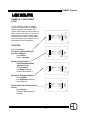
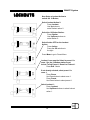
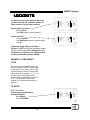
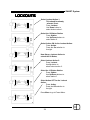
1
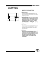
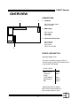
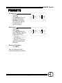
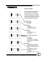
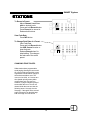
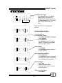
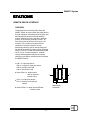
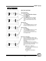
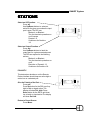
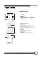
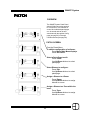
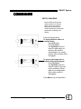
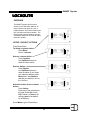
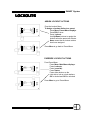
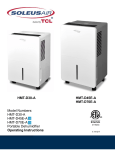
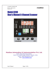
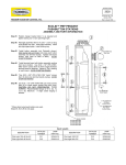
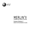
Electronics Diversified, Inc..
SMART System
User Manual
Revision C, April 2005
©2005 Electronics Diversified, Inc.
SMART System
TABLE OF CONTENTS
OVERVIEW
Master Station buttons......... 2
Connections.........................3
Power Consumption..............3
PRESETS
Overview............................. 4
Activation............................ 4
Editing................................ 4
Global Presets..................... 6
XGlobal Presets...................8
STATIONS
Overview............................. 9
SlaveLCD............................ 9
10 Button.............................12
2 Button...............................13
Digital Slider........................ 14
Remote Device Interface.......18
IR Remote Station................20
PATCH
Overview............................. 22
Patch Screen....................... 22
Non-Dimming....................... 23
COMBINES
Overview............................. 24
Activation............................ 24
Overlapping Combines..........24
Combine Setup.................... 25
How: Preset vs. Zone............26
XGlobals..............................27
Patch Page switching............28
Example 2: Left-side preset..33
lock, right-side preset unlock
TIMECLOCK
Overview............................ 37
Setup Clock........................37
Setup Events......................38
Turn On/Off Events..............39
CONFIG SETTINGS
Remote Edit........................40
Password............................40
Master Room Assignment....40
Activate Patch.................... 41
Blackout.............................41
PASSWORD
Changing Passwords........... 42
CLEARING THE SYSTEM
Clearing and Setup............43
STATION WIRING
Cabling...............................44
HARDWARE PIECES
Overview............................ 45
Removal of faceplate...........45
LOCKOUTS
Overview............................. 29
Setup Lockout Actions.........29
Assign Lockout Actions.........30
Lockout Override..................30
Example1: 0ne preset lock.....31
1
SMART System
OVERVIEW
MASTER STATION BUTTONS
1
1
1. Mapped Buttons:
Illuminating Buttons mapped to the display. Any
button press results in the execution of the feature
mapped to the button.
2
4
3
2. Up/ Down Buttons:
Allows user to control highlighted feature displayed
by the Mapped Buttons. Mapped buttons are ued to
adjust levels, set time or curse through character
fieldsdepending on thier set function. Character
fields will go SPACE, ! ,” , #, $, %, &, ’, (, ), *, +, ,,
-, ., 0 through 9, :, ;, <, =, >, ?, @, A through Z, [,
], ^, _, ’, a through z.
3. Menu Button:
Gives access between the preset menu page and
a menu of 8 other selections: ClearSys, Stations,
DimPatch, Combines, Lockouts, Timers, Password, and Config.
4. Edit Button:
When in the Preset activation page this button will
allow the user to toggle between the 3 sets of
preset pages. Within one of the Menu pages, it will
allow the user to cycle through pages of one of the
other topics: ClearSys, Stations,Dim Patch,
Combines, Lockouts, Timers, Password, and
Configurations.
2
SMART System
OVERVIEW
CONNECTORS
1
2
1. Combines:
PIN 1-8: Combine Inputs
PIN 10: Ground
2. DMX Output:
PIN 1: Ground
PIN 2: DataPIN 3: Data+
3. Power/Serial Connection:
PIN 1: Ground
PIN 2: Serial +
PIN 3: Serial PIN 4: +9 to 24 VDC
3
POWER CONSUMPTION
Operating Voltage: 9-24V
For small (1-8 Stations) systems 15VDC is
sufficient. Larger systems (9-16 Stations) must
use a 24VDC Power Supply.
Current (12VDC)
Master Station
LCD Slave
Station
110mA
50mA
2/10/IR Stations
60mA
100mA*
100mA
Slider Stations
RDI
* Rating based upon 10 channel
slider. Lesser channel models will
have a smaller maximum value.
3
SMART System
PRESETS
OVERVIEW
PR1
PR2
PR3
Off
PR1
PR2
PR3
Off
The SMART System has 117 presets
total. Each of the 8 rooms have 13 user
editable presets, plus 13 XGlobal
Presets. The user has access to 7
presets at one time from the Preset
Menu. To access the other six presets,
press the More button. The 13th preset,
labeled OFF will be accessable in both
screens.
PR4
PR5
PR6
More
PR4
PR5
PR6
More
EDITING LEVELS/TIMES
To Edit Presets,
Press Edit.
Rm 1
Pr 1
Zn 1
Lv 100%
Full
+10
-10
Off
Rm 1
Pr 1
Zn 1
Lv 100%
Full
+10
-10
Off
Rm 1
Pr 1
Zn 1
Lv 100%
Rm 1
Pr 1
Zn 1
Lv 100%
Select Room:
Press Rm.
Use Up/Down buttons to
select room.
Select Preset:
Press Pr.
Use Up/Down buttons to
select preset.
Select Zone to be edited:
Press Zn.
Use Up/Down buttons to
select zone.
Full
+10
-10
Off
Adjust Level:
Press Lv.
Use Up/Down buttons to
adjust level or use
Full,Off,+10 (increase by
10%) or -10% (decrease
by 10%).
Full
+10
-10
Off
4
SMART System
PRESETS
Set Fade Time:
Press Edit.
Select Tm.
Use Up/Down buttons to
increment by seconds,
Min-/Min+ to increment
by minutes and -10/+10
to increment by 10
second intervals.
Rm 1
Pr 1
Tm 00:05
Global no
Name Preset:
Press Edit.
Select Name.
Use Up/Down buttons to
select character. Character
fields will go SPACE, ! ,”
, #, $, %, &, ’, (, ), *, +, ,, -,
., 0 through 9, :, ;, <, =, >,
?, @, A through Z, [, ], ^, _,
’, a through z. Use !, 0, a,
and A to quickly jump to
characters.
Rm 1
Pr 1
Name PR1
Lockout None
Return to Preset Menu:
Press Menu.
Note: All changes are being
recorded while the user is editing.
5
+Min
+10
-10
-Min
!
0
a
A
SMART System
PRESETS
GLOBAL PRESETS
PR1
PR2
PR3
Off
Rm 1
Pr 1
Zn 1
Lv 100%
Rm 1
Pr 1
Zn 1
Lv 100%
Normal presets allow levels to be adjusted
within a room and that room only. Global
presets allow the user to adjust different
zones in different rooms. Users can inhibit or
“skip” zones so that they will not be affected
by the preset. A global preset is most useful in
cases where lights in distant rooms need to be
turned on simultaneously or where a special
preset is needed for system wide control.
PR4
PR5
PR6
More
From Preset Menu,
To create a global,
press Edit.
Full
+10
-10
Off
Select Room:
Press Rm.
Use Up/Down buttons to
select room for the preset.
Full
+10
-10
Off
Select Preset:
Press Pr.
Use Up/Down buttons to
select preset.
Rm 1
Pr 1
Tm 00:05
Global no
+Min
+10
-10
-Min
Rm 1
Pr 1
*Global*
Full
+10
-10
Off
Rm 1
*GLOBAL*
Zn 1
*Rm1*
Lv 100% *Pr1*
Skip yes
Activate Global Function for this
Preset:
Press Edit.
Press Global.
Press Up button. The display
should change from Global no to
Global yes.
Select Room:
Press Edit twice. The display
should show Global below Rm
and Pr in the left hand part of the
screen.
Press Edit again.*GLOBAL*
should display at the top.
Press Rm.
Use Up/Down buttons to select
room.
Full
+10
-10
Off
6
SMART System
PRESETS
Select Zone to be edited:
Press Zn.
Use Up/Down buttons to
select zone.
Adjust Level:
Press Lv.
Use Up/Down buttons to
adjust level or use Full,Off,+10
(increase by 10%) or -10%
(decrement by 10%).
Unskip Zone:
Press Skip.
Press Down button. Skip yes
should change to Skip no. A
zone that is left on Skip yes will
not be affected by this preset.
Set Fade Time:
Press Edit.
Select Tm.
Use Up/Down buttons increment by seconds, Min-/Min+
increment by minutes and -10/
+10 to increment by 10 second
intervals.
Name Preset:
Press Edit.
Select Name.
Use Up/Down buttons to select
character. Character fields will go
SPACE, ! ,” , #, $, %, &, ’, (, ), *,
+, ,, -, ., 0 through 9, :, ;, <, =,
>, ?, @, A through Z, [, ], ^, _,
’, a through z. Use !, 0, a,
and A to quickly jump to
characters.
Rm 1
*GLOBAL*
Zn 1
*Rm1*
Lv 100%
*Pr1*
Skip yes
Full
+10
-10
Off
Rm 1
*GLOBAL*
Zn 1
*Rm1*
Lv 100%
*Pr1*
Skip yes
Full
+10
-10
Off
Rm 1
*GLOBAL*
Zn 1
*Rm1*
Lv 100%
*Pr1*
Skip yes
Full
+10
-10
Off
Rm 1
Pr 1
Tm 00:05
Global no
+Min
+10
-10
-Min
Rm 1
Pr 1
Name PR1
Lockout None
Return to Preset Menu:
Press Menu.
7
!
0
a
A
SMART System
PRESETS
XGLOBAL PRESETS
PR1
PR2
PR3
Off
Rm 1
Pr 1
Zn 1
Lv 100%
Rm X
Pr 1
*Global*
Rm 1
*GLOBAL*
Zn 1
*RmX*
Lv 0%
*Pr1*
Skip yes
PR4
PR5
PR6
More
Full
+10
-10
Off
Full
+10
-10
Off
Full
+10
-10
Off
13 XGlobal Presets can replace presets in
combined rooms. The presets are not associated
with any room, thus dsignated on the master
station as X. Because they are a global preset,
they will affect only those zones in rooms that
are not “skipped”. They can only be activated with
a combine function and only be activated from
stations within the combined room.
To assign an XGlobal Preset to a Combine
function, turn to page 25.
From Preset Menu,
To create an XGlobal,
press Edit.
Select Room:
Press Rm.
Use Up button to select room
X.The display should show
Global below Rm and Pr in the
left hand part of the screen
Press Edit.
Select Roomto Edit:
Press Edit again.*GLOBAL*
should display at the top.
Press Rm.
Use Up/Down buttons to select
room.
Follow the directions on page 7 for
editing Global presets.
8
SMART System
STATIONS
OVERVIEW
The SMART System can handle up to 16 stations:
z 6 types of stations are available on the SMART System: LCD
Slave, 10 Button, 2 Button, Digital Slider, IR Remote, and Remote
Device Interface.
z
Stations can be spread out over 1000 feet of Alpha 1133.
z The SMART System can only address one station and cannot
allow “mirroring” of stations.
z The Master Station itself can be used as a station and is non
addressable.
To read how to select the room the Master station will operate
turn to page 31.
SLAVE LCD STATION
1
1
1. Mapped Buttons:
Illuminating Buttons mapped to the display.
Any button press results in the execution of
the feature mapped to the button.
2
2. Up/ Down Buttons:
Allows user to control highlighted feature
displayed by the Mapped Buttons. Used to
adjust levels or set time.
4
3. Menu Button:
Returns to the preset menu page.
4. Edit Button:
Prompts for the next page within the Preset
edit pages
9
3
SMART System
STATIONS
To Edit Presets,
Press Edit.
PR1
PR2
PR3
Off
Rm 1
Pr 1
Zn 1
Lv 100%
Rm 1
Pr 1
Zn 1
Lv 100%
PR4
PR5
PR6
More
Select Preset:
Press Pr.
Use Up/Down buttons to
select preset.
Select Zone to be edited:
Press Zn.
Use Up/Down buttons to
select zone.
Full
+10
-10
Off
Adjust Level:
Press Lv.
Use Up/Down buttons to
adjust level or use
Full,Off,+10 (increase by
10%) or -10% (decrease by
10%).
Full
+10
-10
Off
Rm 1
Pr 1
Zn 1
Lv 100%
Full
+10
-10
Off
Rm 1
Pr 1
Tm 00:05
Global no
+Min
+10
-10
-Min
Set Fade Time:
Press Edit.
Select Tm.
Use Up/Down buttons to
increment by seconds,
Min-/Min+ to increment
by minutes and -10/+10
to increment by 10
second intervals.
Return to Preset Menu:
Press Menu.
10
SMART System
STATIONS
Lockouts
Timers
Password
Config
Clear Sys
Stations
Dim Patch
Combines
SETUP LCD:
From Preset Menu,
On the Master Station,
Press Menu. Main Menu displays.
Press Stations.
Press Station 0.
Use Up/Down arrows to select a
Station. In the station name, LCD
refers to a Slave LCD Station.
Select Room:
Press Room.
Use Up/Down buttons to assign a
room to a station.
Select Backlight:
Press BL.
Use Up/Down button to select
between backlight constant on,
constant off, or instant on/ delay
off.
Test the Station:
Press Test.
Station will flash LEDs
Press any other button to resume
normal functions.
Station 0
Room1
Test
Station 1
Room1
BL: delay
Station 1
Room1
BL: delay
LCD
Test
LCD
Test
Station 1
Room1
BL: delay
LCD
Test
Return to Preset Menu:
Press Menu.
11
SMART System
STATIONS
10 BUTTON STATION
1
2
3
1. Presets 1-6 (7-12 when More is activated)
Press a button to execute a preset in a room
2. Master Room Level Buttons
Adjust levels up or down in all zones within a
room.
3. More Button
Switches between Presets 1-6 and 7-12
4 Off Button
Press to Execute Preset 13 (Off)
SETUP 10 BUTTON:
4
Lockouts
Timers
Password
Config
Clear Sys
Stations
Dim Patch
Combines
Station 0
Room1
Test
Station 1
Room1
10Btn
Test
From Preset Menu,
On the Master Station,
Press Menu. Main Menu displays
Press Stations.
Press Station 0.
Use Up/Down arrows to select a
Station. In the station name, 10Btn
refers to a 10 Button Station.
Select Room:
Press Room.
Use Up/Down buttons to assign a
room to a station.
Test the Station:
Press Test.
Station will flash LEDs
Press any other button to resume
normal functions.
Return to Preset Menu:
Press Menu.
Station 1
Room1
10Btn
Test
12
SMART System
STATIONS
2 BUTTON STATION
1
1. On Button
Press button to execute an assigned preset
(see below).
2
2. Off Button
Press button to execute preset 13 (Off)
SETUP 2 BUTTON:
Clear Sys
Stations
Dim Patch
Combines
From Preset Menu,
On the Master Station,
Press Menu. Main Menu Displays.
Press Stations.
Press Station 0.
Use Up/Down arrows to select a
Station. In the station name, 2Btn
refers to a 10 Button Station.
Select Room:
Press Room.
Use Up/Down buttons to assign a
room to a station.
Lockouts
Timers
Password
Config
Station 0
Room1
Test
Station 1
2Btn
Room1
On preset: 1
Test
Select On Preset:
Press On preset.
Use Up/Down buttons to assign a
preset on a button.
Test the Station:
Press Test.
Station will flash LEDs
Press any other button to resume
normal functions.
Return to Preset Menu:
Press Menu.
Station 1
2Btn
Room1
On preset: 1
Test
Station 1
2Btn
Room1
On preset: 1
Test
13
SMART System
STATIONS
DIGITAL SLIDER STATION
9
8
1
1. Presets 1-6 (7-12 when More is
activated)
Press a button to execute a preset in a
room.
2. Record Button
Used in saving levels to a preset. Also,
this button is used for paging different
channels. (See recording presets and
changing zone pages on pages 15
and 16).
2
7
3 4
3. Off Button
Press to Execute Preset 13 (Off).
5 6
4. More Button
Toggles between Presets 1-6 and 7-12.
5. Master/Fade Rate Button
Toggles the M/R display (9) from
displaying master control use and the
fade rate of an executed preset. It will
also toggle the use of the M/R level
controls (6) from adjusting all zones
within a room to adjusting preset fade
rates when recording.
6. Master/Fade Rate Control
Press to raise or lower level in a room
or adjust fade rate as desired (See
recording presets about fade rate
changes on page 15).
7. Channel Level Controls
Press to raise or lower an individual
channel level within a room.
8. Channel Levels
10-segment LEDS show intesity values
from 0 to 100% on each channel.
9. M/R Levels
10-segment LEDs shows master fader
action and fade rates up to 5 minutes.
14
SMART System
STATIONS
To Record a Preset:
Adjust Channel Level Controls to desired levels.
Press and hold Record button.
Press Preset to be stored in.
Release both buttons.
View Fade Rate:
Press M/R button.
To Change Fade Rate of a Preset:
View Fade Rate.
Press and hold Record button.
Use M/R Control to raise or
lower fade rate.
Release Record when finished editing. This changes
the fade rate of the active
preset.
CHANGING ZONE PAGES:
Slider stations have programmable
zonal paging, allowing the user to edit
all or some of the zones within a room
reguardless of slider station configuration and zones within a room. The
user can view 4,6,8, or 10 zones at a
time (based upon how many slider
controls there are). The user can
advance or “page” to another group of
zones within the room. Thus on a 4
channel slider the user can view the
following zones: 1 through 4 on the
first page, 5 through 8 on the second
page, 9 through 12 on the third page,
and 13 through 16 on the fourth.
15
SMART System
STATIONS
To Change Zone Page,
Press Record button and Down
Zone button on the page to be
viewed (Ex.First Page would be the
first Down Zone button). The lowest
LED over the slider button will
flash.
Note: The LED for the first page will
not flash.
Clear Sys
Stations
Dim Patch
Combines
Lockouts
Timers
Password
Config
SETUP SLIDER STATION:
From Preset Menu,
On the Master Station,
Press Menu. Main Menu displays.
Press Stations.
Press Station 0.
Use Up/Down arrows to select a
Station. In the station name, Sldr
refers to a Slider Station.
Station 0
Room1
Test
Station 1
Sldr
Room1
Channels: 1
Page: 1
Station 1
2Btn
Room1
Channels: 1
Page: 1
Station 1
2Btn
Room1
Channels: 1
Page: 1
Select Room:
Press Room.
Use Up/Down buttons to assign a
room to a station.
Test
Set Channel Size of Slider :
Press Channels.
Use Up/Down buttons to designate
the maximum number of zones that
can be displayed on that station.
Test
Test the Station:
Press Test.
Station will flash LEDs
Press any other button to resume
normal functions.
Test
Return to Preset Menu:
Press Menu.
16
SMART System
STATIONS
REMOTE DEVICE INTERFACE
OVERVIEW
The Remote Device Interface (RDI) allows the
SMART System to communicate with other devices
through maintain or momentary switching. Each port
has a latched(On) function and unlatched(Off)
function, allowing the user to activate to separate
fuctions on one switch ( Example: Preset 1 for
Port1 On function and Preset Off for port 1 Off
function). This is useful for turning on and off
combines or a blackout switch for a room.
Momemtary switching can be used by setting the
On and Off functions to the same setting. (Example:
Preset 1 for Port 1 On and Off functions and Preset
Off for Port 2). A custom keypad for a master
control panel/swtichboard may use momentary
switching on the RDI to activate fuctions throughout
the SMART System.
1. PIN 1-12: input port latches
PIN 13: common for input port latches
PIN 14: 9-24VDC from LAN
PIN 15: Ground from LAN
2
2. Input LEDs 1-12: lamp on when
latch is closed by
outside source
3
1
3. PIN 1-12: output port latches
PIN 13: common for output port
latches
Power/Serial
Connection
4. Output LEDs 1-12: lamp on when RDI has
closed the latch
17
4
SMART System
STATIONS
SEUP RDI FUNCTIONS:
Lockouts
Timers
Password
Config
Clear Sys
Stations
Dim Patch
Combines
Station 0
Room1
Test
From Preset Menu,
On the Master Station,
Press Menu. Main Menu displays.
Press Stations.
Press Station 0.
Use Up/Down arrows to select a
Station. In the station name, RDI
refers to the Remote Device Interface.
Select a Port:
Press Port.
Use the Up/Down buttons to select
an input or output port latch (1-12).
Station 1
Port 1
Room 1
On: none
RDI
Station 1
Port 1
Room 1
On: none
RDI
Station 1
Port 1
Room 1
On: none
RDI
on
off
out
pol
Select a Room:
Press Room.
Use the Up/Down buttons to select
a room that RDI will activate or
sense. The same port can be used
for multiple rooms.
on
off
out
pol
on
off
out
pol
Select an On Function:
Press the 4th button down on the
left. When this button is lit, the user can
designate functions to the RDI
Press on
Use Up/Down buttons to select an
action for the given room when the input
port has been latched. The RDI
can:
z Blackout/ un-Blackout
z Turn the timeclock operations on
or off execute
z Presets1-13
z Combine or UnCombine
1-8.
18
SMART System
STATIONS
Select an Off Function :
Press off
Use Up/Down buttons to select an
action for the given room when the input
port is open. The RDI can:
Blackout/ un-Blackout
Turn the timeclock operations on
or off execute
Presets1-13
Combine or UnCombine
1-8.
Station 1
Port 1
Room 1
On: none
RDI
on
off
out
pol
Select an Output Function:
Press out
Use Up/Down buttons to latch the
output port for a given executed preset
The RDI can respond to the following
actions:
Blackout/ un-Blackout,
Turn the timeclock operations on
or off,
Execution of Presets1-13,
Combine or UnCombine 1-8.
POLARITY:
This determines whether or not the Remote
Device Interface should keep an active high or
active low on a selected port.
Give the Polarity of the Port:
Press pol.
Press Up button for the RDI to pull up
high to latch or signal action. The
display will show Pol: high. Press
Down button for the RDI to pull down
low to latch or signal action.The display
will show Pol: low.
Return to Preset Screen:
Press Menu.
19
Station 1
Port 1
Room 1
On: none
RDI
on
off
out
pol
SMART System
STATIONS
IR REMOTE STATION
1
IR STATION:
1. IR Sensor
Receives infrared signals from remote control
2. LED Indicator
Indicates function execution has been
received
2
IR REMOTE CONTROL:
4
1
3
1. Presets 1-12
Press a button to execute a preset in a room
2. Master Room Level Buttons
Adjust levels up or down in all zones within a
room.
3. Off Button
Press to Execute Preset 13 (Off)
4. LED Indicator
Indicates function execution has been
transmitted
2
20
SMART System
STATIONS
SETUP IR REMOTE:
Lockouts
Timers
Password
Config
Clear Sys
Stations
Dim Patch
Combines
Station 0
Room1
Test
From Preset Menu,
On the Master Station,
Press Menu. Main Menu displays
Press Stations.
Press Station 0.
Use Up/Down arrows to select a
Station. In the station name, IR
refers to a 10 Button Station.
Select Room:
Press Room.
Use Up/Down buttons to assign a
room to a station.
Station 1
Room1
10Btn
Test
Return to Preset Menu:
Press Menu.
21
SMART System
PATCH
OVERVIEW
Clear Sys
Stations
Dim Patch
Combines
The SMART System Patch Panel
allows 250 dimmers to be patched
to a maximum of 100 channels or
zones. Nine individual patch pages
can be stored and can be activated manually through the Config
page (see page 33) or through
Combine Actions (see page 26).
Lockouts
Timers
Password
Config
PATCH SCREEN:
Patch 1
Dim 1
Room 1
Zone 1
From the Preset Menu,
To edit the configuration of a dimmer,
Press Menu. Main Menu displays.
Press Dim Patch.
Select a Patch Page to edit:
Press Patch.
Use Up/Down buttons to select
patch page.
Patch1
Dim 1
Room 1
Zone 1
Select Dimmer to configure:
Press Dim.
Use Up/Down buttons to select
patch page.
Patch 1
Dim 1
Room 1
Zone 1
Assign a Dimmer to a Room:
Press Room.
Use Up/Down buttons to assign
dimmer to a room.
Assign a Dimmer to a Zone within the
room:
Press Zone.
Use Up/Down buttons to assign
dimmer to a zone.
Patch 1
Dim 1
Room 1
Zone 1
22
SMART System
PATCH
NON DIMMING:
For lights that are disigned to turn on and
off without dimming, the SMART System
has a NonDim feature. NonDim dimmers will
turn on above 50% and off below 50%.
From the Patch Screen,
Press Edit.
Press Nondim.
Press Up button assign a nondim,
press Down button to dim.
Note: Multiple Dimmers can be assigned to a
zone within a room , but multiple zones cannot
be assigned to the same dimmer.
23
Patch 1
Dim 1
Nondim: yes
SMART System
COMBINES
OVERVIEW
Combines allow multiple rooms function
as one. This scenario is most useful in
aditoriums or meeting rooms with
adjoining areas. The adjoining areas will
either mimic or activate presets in
reference to the main area.
OVERLAPPING COMBINE
ACTIONS
A combine action can combine from two to
eight rooms by a single combine activation
switch. If two combine actions are joined
with an overlapping of rooms between
them, the SMART System will conveniently
operate the area as if it were one large
combine action.
ACTIVATION
The combine actions can be activated
either by a physical switch wired via the
backside of the Master Station or through
the use of a Remote Device Interface.
The Combine Actions are last action
events and will take effect on the next
preceeding execution of a preset within
the combined rooms .
To learn more about the RDI turn to
page 17.
24
SMART System
COMBINES
COMBINE SETUP
Clear Sys
Stations
Dim Patch
Combines
From Preset Menu,
To Setup A Combine,
Press Menu, Main Menu displays
Press Combines.
Select a Combine:
Press Combine.
Use Up/Down buttons to select
a Combine.
Combine 1
How: Preset
Room 1
Attach?
Select Rooms to Combine:
Press Room.
Use Up/Down buttons to select
one room to combine.
Press Attach?
Press Room.
Use Up/Down buttons to select
another room to combine.
Press Attach?
Select and attach another room
as needed.
Combine 1
How: Preset
Room 1
Attach?
Patch 1
Dim 1
Room 2
Attach? 1
EXAMPLE:
To Combine Rooms 2,3, and 8.
Select a Combine
Combine room 2:
Press Room.
Press Up button.
Press Attach?
Combine rooms 2 and 3:
Press Up button.
Press Attach?
Combine rooms 2, 3, and 8:
Press Up button 5 times.
Press Attach?
To exit and save, press Menu.
Combine 1
How: Preset
Room 23
Attach?
Combine 1
How: Preset
Room 23
8
Attach?
25
Lockouts
Timers
Password
Config
SMART System
COMBINES
HOW?: PRESET VS.
ZONE COMBINING
The SMART System can combine
rooms in following ways: through
preset activation or zone copying.
When rooms are combined through
presets, the activation of one
preset in one room will cause the
activation of the same preset
number in other rooms. Thus, if
Preset 1 was activated in room 1 in
a two room senerio, Preset 1 in
Room 2 would activate. When
rooms are combined through zones,
zones levels of one room’s preset
will follow into other combined
rooms. Back to the two room
senerio, if Preset 1 was activated in
room 1 and zones 1 through 4 are
at full for that preset, then zones 1
through 4 in room 2 will go to full. If
the two rooms were identical, they
would both have the same look.
Combine 1
How: zone
Room 1
Attach? 123
Within Combine Menu,
To Designate Zone Combining,
Press How:
Press Up button for preset
combing or press Down.
button for zone combining.
Note: The setting of the combine
“How” is a global setting. All
combine actions will either be
preset or zone.
26
SMART System
COMBINES
XGLOBALS
One of the 13 XGlobal presets can
replace 1 preset per combine
action. The Xglobal Preset will
replace only presets that are within
the combined rooms. Since they
are global presets, they will affect
all zones in every room unless they
are skipped.
For more on XGlobals turn to
page 8.
From the Combine Menu,
To replace a Presets with an XGlobal
Preset,
Press Edit.
Combine 1
How: Preset
Room 1
Attach?
Select Presets to be replaced:
Press Replace Pr.
Use Up/Down buttons to select
preset. To not replace a preset
select none.
Combine 1
Replace Pr none
with X Gpr none
Zone 1
Select XGlobal Preset:
Press with X GPr.
Use Up/Down buttons to select
XGlobal preset. To not replace a
preset select none.
Combine 1
Replace Pr 1
with X Gpr none
Zone 1
27
SMART System
COMBINES
PATCH CHANGING
Each combine action has the
ability to switch to a different
patch. This is most useful in
head/ table scenarios where
XGlobal substitutions and simple
preset/zone combining is not
desired.
Combine 1
On Patch none
Off Patch none
Zone 1
Combine 1
On Patch 2
Off Patch none
Zone 1
From the Combine Menu,
To Change Patches when in a
combine action,
Press Edit twice.
Press On Patch.
Use Up/Down buttons to
select the patch page you
will use in the combine.
Select none to not change
patches when combine action
is engaged.
To go to a patch page when a
combine action is disengaged.
Press Off Patch.
Use Up/Down buttons to
select the patch to go back
to after combining. Select
none to not change patch
after combine action is
disengaged.
Press Menu to go to Preset Menu.
28
SMART System
LOCKOUTS
OVERVIEW
The SMART System has 20 lockout
actions to lock and unlock stations. All
lockout actions can effect the one or
multiple stations. One lockout function can
lock one station and unlock another . The
lockout actions are activated by a preset.
The Master Station can override all station
lockouts if needed.
Clear Sys
Stations
Dim Patch
Combines
Lockouts
Timers
Password
Config
SETUP LOCKOUT ACTIONS
From Preset Menu,
To Setup a Lockout Action,
Press Menu.
Press Lockouts.
Lockout 1
Station 0
Action: none
(overrride)
On
Off
None
Lockout 1
Station 0
Action: none
(overrride)
On
Off
None
Select a Lockout Action:
Press Lockout.
Use Up/Down buttons to
select a lockout action.
Select a Station:
Press Station.
Use Up/Down buttons to
select a station (If you forgot
your station’s address press
Menu twice, then Stations,
and find your station in one of
the 16 slots.)
Lockout 1
Station 1
Action: none
Zone 1
Select the Action for the Lockout
Action:
Press Action.
Press one of the selections to
the right: Select On to lock,
Off to unlock, or None to do
nothing (none is the default
for all stations).
Press Menu to go to Preset Menu.
29
On
Off
None
SMART System
LOCKOUTS
ASSIGN LOCKOUT ACTIONS
PR1
PR2
PR3
Off
Rm 1
Pr 1
Name PR1
Lockout None
PR4
PR5
PR6
More
+Min
+10
-10
-Min
From the Lockout Menu,
To Assign a Lockout Action to a preset,
Press Menu. Preset Menu displays.
Press Edit 3 times
Press Lockout.
Use Up/Down buttons to assign the
lockout action the preset will activate.
None means that no lockout actions
have been assigned.
Press Menu to go back to Preset Menu.
OVERRIDE LOCKOUT ACTIONS
Lockout 1
Station 0
Action: none
(overrride)
On
Off
None
From Preset Menu,
Press Menu. Main Menu displays.
Press Lockouts.
Press (override).
Press Status.
Press either buttons on the
right side to lock or unlock stations.
On for locked and Off for unlocked.
Press Menu to go to Preset Menu
Station 0
Type LCD
Status: Off
On
Off
30
SMART System
LOCKOUTS
EXAMPLE: A ONE PRESET
LOCK
For the following example, the SMART
System will lock and unlock a 10-Button
station in a single room scenario. The
system will be setup such that Preset 1 in
Room 1 will lock this station. To unlock, an
alternate preset on another station within
the same room will have to be activated to
unlock this station. In this example, the 10Button station will be on address 0.
Clear Sys
Stations
Dim Patch
Combines
Lockouts
Timers
Password
Config
TO SETUP:
From Preset Menu,
To Setup a Lockout Action to
lock the 10-Button,
Press Menu.
Press Lockouts.
Select Lockout Action 1:
This should be already
selected, if not:
Press Lockout.
Use Down button to
select lockout action 1.
Lockout 1
Station 0
Action: none
(overrride)
On
Off
None
Lockout 1
Station 0
Action: none
(overrride)
On
Off
None
Select the 10-Button Station:
Press Station.
Use Up/Down buttons to
select station 0.
Lockout 1
Station 1
Action: On
Zone 1
Select Action ON for the Lockout
Action:
Press Action.
Press the On selection to
the right.
31
On
Off
None
SMART System
LOCKOUTS
Lockout 2
Station 0
Action: none
(overrride)
On
Off
None
Now Setup a Lockout Action to
unlock the 10-Button,
Select Lockout Action 2:
Press Lockout.
Use Up button to
select lockout action 2.
Select the 10-Button Station:
Press Station.
Use Up/Down buttons to
select station 0.
Lockout 2
Station 0
Action: none
(overrride)
On
Off
None
Select Action OFF for the Lockout
Action:
Press Action.
Press the Off selection to
the right.
Press Menu to go to Preset Menu.
Lockout 2
Station 1
Action: Off
Zone 1
On
Off
None
Lockout 1 now must be linked to preset 1 in
room 1 for the 10-Button station to get
locked. To link Preset 1, Room1 to Lockout 1.
Press Edit 3 times
PR1
PR2
PR3
Off
Rm 1
Pr 1
Name PR1
Lockout 1
PR4
PR5
PR6
More
+Min
+10
-10
-Min
If not already selected, select preset 1 in
room 1:
Press Room.
Use Down button to select room 1.
Press Preset.
Use Down button to select preset 1.
Select Lockout 1:
Press Lockout.
Use Up/Down buttons to select lockout
action 1.
32
SMART System
LOCKOUTS
Lockout 2 now must be linked to the other
presets to unlock the 10-Button station. To
setup Lockout 2 to the other stations:
Rm 1
Pr 2
Name PR2
Lockout 1
+Min
+10
-10
-Min
Rm 1
Pr 2
Name PR2
Lockout 2
+Min
+10
-10
-Min
Select preset 2 in room 1:
Press Preset.
Press Up button to select preset 1.
Select Lockout 1:
Press Lockout.
Use Up/Down buttons to select lockout
action 2.
Repeat the same action for presets 3
through 13 (OFF is 13). Now all presets except
preset 1 will lock the station. Remember once
the station is locked out, it is inoperable and
must be unlocked by another station.
EXAMPLE: A ONE PRESET
LOCK
For this example, the SMART System will
lock and unlock the same 10-Button station
in a single room. The system will be setup
such that presets located on the left hand
side of the controls (presets 1, 2, 3, 7, 8, 9,
and OFF) will lock the 10-Button, and
presets on the right hand side (presets 4, 5,
6, 10, 11, and 12 ) will unlock. In this
example, the 10-Button station will be on
address 0.
TO SETUP:
From Preset Menu,
To Setup a Lockout Action to
lock the 10-Button,
Press Menu.
Press Lockouts.
Clear Sys
Stations
Dim Patch
Combines
33
Lockouts
Timers
Password
Config
SMART System
LOCKOUTS
Lockout 1
Station 0
Action: none
(overrride)
30
Lockout 1
Station 0
Action: none
(overrride)
On
Off
None
On
Off
None
Select Lockout Action 1:
This should be already
selected, if not:
Press Lockout.
Use Down button to
select lockout action 1.
Select the 10-Button Station:
Press Station.
Use Up/Down buttons to
select station 0.
Select Action ON for the Lockout Action:
Press Action.
Press the On selection to
the right.
Lockout 1
Station 1
Action: On
Zone 1
Lockout 2
Station 0
Action: none
(overrride)
On
Off
None
On
Off
None
Now Setup a Lockout Action to
unlock the 10-Button,
Select Lockout Action 2:
Press Lockout.
Use Up button to
select lockout action 2.
Select the 10-Button Station:
Press Station.
Use Up/Down buttons to
select station 0.
Lockout 2
Station 0
Action: none
(overrride)
On
Off
None
Select Action OFF for the Lockout
Action:
Press Action.
Press the Off selection to
the right.
Press Menu to go to Preset Menu.
Lockout 2
Station 1
Action: Off
Zone 1
On
Off
None
34
SMART System
LOCKOUTS
Lockout 1 now must be linked to presets 1, 2,
3, 7, 8, 9, and OFF in room 1 for the 10-Button
station to get locked. To link Preset 1, Room1
to Lockout 1,
Press Edit 3 times
PR1
PR2
PR3
Off
PR4
PR5
PR6
More
If not already selected, select preset 1 in
room 1:
Press Room.
Use Down button to select room 1.
Press Preset.
Use Down button to select preset 1.
Select Lockout 1:
Press Lockout.
Use Up/Down buttons to select lockout
action 1.
Rm 1
Pr 1
Name PR1
Lockout 1
+Min
+10
-10
-Min
Rm 1
Pr 2
Name PR1
Lockout 1
+Min
+10
-10
-Min
Select Preset 2:
Press Preset.
Use Up button to select preset 2.
Select Lockout 1:
Press Lockout.
Use Up/Down buttons to select lockout
action 1.
To do Presets 3,7,8,9, and OFF, follow the
last two steps. Remember that OFF is preset
13.
35
SMART System
LOCKOUTS
Lockout 2 now must be linked to presets 4, 5,
6, 10, 11,and 12 in room 1 for the 10-Button
station to get unlocked. To link Preset 4,
Room1 to Lockout 2,.
Press Edit 3 times
Rm 1
Pr 4
Name PR4
Lockout 2
+Min
+10
-10
-Min
Select preset 4 in room 1:
Press Preset.
Use Up button to select preset 4.
Select Lockout 2:
Press Lockout.
Use Up/Down buttons to select lockout
action 2.
Rm 1
Pr 5
Name PR5
Lockout 2
+Min
+10
-10
-Min
Select Preset 5:
Press Preset.
Use Up button to select preset 5.
Select Lockout 1:
Press Lockout.
Use Up/Down buttons to select lockout
action 2.
To do Presets 5,6,10,11, and 12, follow the
last two steps.
36
SMART System
TIMECLOCK
OVERVIEW
The SMART System has 20
timeclock events. Each event can
be programmed to activate one
preset in one room. Events are
setup on a weekly timer and
individual events can be programmed from once a week to
every day. The operations of the
time clock can be turned on and off
as needed.
Clear Sys
Stations
Dim Patch
Combines
Lockouts
Timers
Password
Config
SETUP CLOCK
From Preset Menu,
To Change Clock Time,
Press Menu.
Press Timers.Timer
Menu displays.
Press Edit.
Event 1
Room 0
Pr 0
Tm 01:01
Change the Day:
Press Day.
Use Up/Down buttons to
select day.
Change the Hour:
Press Hour.
Use Up/Down buttons to
select hour. Note: clock is in
24 hours (1-12PM is 13-24).
Change the Minute:
Press Min.
Use Up/Down buttons to
select minute.
Press Edit to go intoTimer Menu.
Press Menu to go to Preset Menu.
37
+Hr
-Hr
smtwtfs
Day
Hour
Min
TCO: off
Tue:24:00:00
Day
Hour
Min
TCO: off
Sun:24:00:00
Day
Hour
Min
TCO: off
Sun:12:00:00
SMART System
TIMECLOCK
SETUP EVENTS
Event 1
Room 0
Pr 0
Tm 01:01
Event 1
Room 0
Pr 0
Tm 01:01
Event 1
Room 0
Pr 0
Tm 01:01
Event 1
Room 0
Pr 0
Tm 01:01
+Hr
-Hr
smtwtfs
+Hr
-Hr
smtwtfs
+Hr
-Hr
smtwtfs
+Hr
-Hr
smtwtfs
Event 1
Room 0
Pr 0
Tm 01:01
+Hr
-Hr
sMtwtfs
Event 1
Room 0
Pr 0
Tm 01:01
+Hr
-Hr
sMtwtfs
*
From Timer Menu,
Select an Event:
Press Event.
Use Up/Down buttons to select an
event to edit.
Select the Room Where the Event will
Happen:
Press Room.
Use Up/Down buttons to select a
room.
Select a Preset the Event will Activate:
Press Preset.
Use Up/Down buttons to select
preset.
Set the Time to Activate the Event:
Press Tm.
Use Up/Down buttons to change
time byminutes or the +Hr/-Hr to
change by hours. Note: timer is in
24 hours. (1-12PM is 1324)
Select the Days That the Event Will
Happen:
Press 3rd button on the left
(smtwtfs).
Highlight the day by uppercasing
the day through multiple hits of the
3rd button on the left.(Ex.
smTwtfs -Tuesday is highlighted).
Press the illuminated button to
select the day.
Repeat for multiple days.
38
SMART System
TIMECLOCK
TURNING ON/OFF EVENTS
Event 1
Room 0
Pr 0
Tm 01:01
From Preset Screen,
To Turn On and Off all Events,
Press Menu.
Press Timers. The Timer
Menu comes up
Press Edit.
Press TCO (Time Clock
Overrride).
Press either Up button to
turn off all the events or
Down button to turn them
on.
Press Edit to return to
Timer Menu.
Day
Hour
Min
TCO: off
Note: TCO can be changed
through the RDI.
See page 18 for more details
about RDI functions.
From Timer Menu
To turn off specific events
Select Event:
Press Event.
Use Up/Down buttons to
select event.
Set Room to 0:
Press Room.
Use Down button to go to
0.
Set Preset to 0:
Press Preset
Use Down button to go to
0.
39
+Hr
-Hr
smtwtfs
Tue:24:00:00
Event 1
Room 0
Pr 0
Tm 01:01
+Hr
-Hr
smtwtfs
Event 1
Room 0
Pr 0
Tm 01:01
+Hr
-Hr
smtwtfs
Event 1
Room 0
Pr 0
Tm 01:01
+Hr
-Hr
smtwtfs
SMART System
CONFIGURATION
SETTINGS
REMOTE EDIT
Clear Sys
Stations
Dim Patch
Combines
Remote edit: yes
Password: no
Master room: 1
Active patch: 1
Lockouts
Timers
Password
Config
Allows the user to record live from a station
other than the master. This affects edit
functions on Slider LCDs. If remote edit is set
to no, the LCD will not display any Preset
editing screens, The record button on the
Slider Stations will not work also, except in
paging.
From Preset Screen,
Press Menu. Main Menu displays.
Press Config.
Press Remote Edit.
Press Up button for yes or
Down button for no.
PASSWORD
Password Protection can be set on the
Master Station such that menus dealing
Lockout, Timer, Password, Configuration
Settings, Combines, Dimmer Patches,
System Clearing are safeguarded with a
password. Presets, still can be edited at the
Master and other stations.
The default password is four hits on the top
left button. To edit the password see page
32.
NOTE: Do not end password with a “1.”
Remote edit: yes
Password: no
Master room: 1
Active patch: 1
From Preset Screen,
Press Menu. Main Menu displays.
Press Config
Press Password on.
Press Up button for yes or
Down button for no.
MASTER ROOM ASSIGNMENT
The Master Room can be assigned
any room and does not take up an
address.
40
SMART System
CONFIGURATION
room
SETTINGS (master
continued)
From Preset Screen,
Press Menu. Main.
Menu displays.
Press Config.
Press Master room.
Use Up/Down buttons
to select a room.
Remote edit: yes
Password: no
Master room: 1
Active patch: 1
ACTIVATE PATCH
Select one of the 9 patch tables
available on the SMART System to
be active. For more on patching go
to page 19
Remote edit: yes
Password: no
Master room: 1
Active patch: 1
From Preset Screen,
Press Menu. Main
Menu displays.
Press Config.
Press Active Patch.
Use Up/Down buttons
to select a patch.
BLACKOUT
The SMART System allows the user
to blackout rooms manually if needed.
This feature can also be set by an RDI
(see pages 18-19)
From Preset Screen,
Press Menu. Main
Menu displays.
Press Config.
Press Edit.
Press Room.
Use Up/Down buttons
to blackout/ unblackout
room.
Press Blackout.
Press Up button to turn
blackout on and Down
to turn off.
41
Remote edit: yes
Password: no
Master room: 1
Active patch: 1
Room 1
Blackout: off
Room 1
Blackout: on
SMART System
PASSWORDING
CHANGING PASSWORDS
Clear Sys
Stations
Dim Patch
Combines
Lockouts
Timers
Password
Config
Old Password: ****
Password OK
Old Password: ****
New Password: ****
New Password: ****
The SMART System uses password protection
to prevent unwanted clearing and editing of
the system. The default password is four hits
in the upper left button on the Master Station.
This password can be changed for increased
protection. All buttons on the faceplate are
accessible to making a new four digit code.
For password enabling, turn to page 32.
From Preset Screen,
Press Menu.
Press Password.
Type in Old four digit
password.
Type in New password
Type in New password
again.
After OK, press Menu to
return to Preset Menu.
NOTE: DO NOT TURN THE SMART
SYSTEM OFF DURING ANY PART
OF PROGRAMMING IN THE
PASSWORD.
If inaccurate information is placed in
the SMART System, it will return
back to the Menu Screen.
42
SMART System
CLEARING THE
SYSTEM
CLEARING AND SETUP
Lockouts
Timers
Password
Config
Clear Sys
Stations
Dim Patch
Combines
From the Preset Menu,
Press Menu.
Press Clear Sys.
Enter 4-digit password using the 12
keys on the Master Station:
Default password is 4 hits on
the top left button.
Password:
AFTER THE LAST DIGIT IS PUT IN,
THERE IS NO RETURNING AND
NO OUTSIDE COPY CAN BE
MADE OF THE PROGRAM!
Good bye
Good Bye will appear on the Screen,
verifying erasure.
Select Room Size:
Use Up/Down buttons to
select the number of rooms.
Press Menu.
Select maximum Zone size for each
room:
Press a room button (Rm1,
Rm2, etc.).
Use Up/Down buttons to set
the maximum number of zones
for that room. The user can
spread the 100 zone limit
across the number of rooms
selected.
Press Menu.
43
Number of rooms: 1
Rm 1
Rm2
Rm3
Rm4
Zn12
Zn12
Zn12
Zn12
-- -- Rm5
-- -- Rm6
-- -- Rm7
-- -- Rm8
Zn12
Zn12
Zn12
Zn12
SMART System
STATION WIRING
Standard cabling: 3 cables
DMX cable: Belden 9842 (1000’)
Power cable: 2 18# AWG (1000’)
LAN cable: Alpha 1133C (1000’)
dimmer
dmx
master
remote
power
remote
remote
lan
power supply
Option 1: 2 cables (both cables total
1000’)
DMX, Power cable: Belden 9843
pair 1 = dmx
pair 2 = +15/24 (both wires)
pair 3 = ground (both wires)
LAN cable: Alpha 1133C
dimmer power
and dmx master
remote
remote
remote
lan
Option 2: 1 cable (500’ w/ up to 8 stations, 1000’ w/ up to 4 stations)
DMX, Power, LAN cable: Belden 9844;
pair 1 = dmx
pair 2 = lan
pair 3 = +15/24 (both wires)
pair 4 = ground (both wires)
dimmer
master
lan, power
and dmx remote
remote
remote
44
SMART System
HARDWARE
PIECES
OVERVIEW
1. Back Circuit Board
Contains electronics for processing
SMART functions.
7 8
2. Standoffs
3. Front Circuit Board
Provides the front end for controls.
4. Standoffs
5. Subplate
Plate used for mounting SMART System. Use #6 screw to mount to electrical
backbox.
6. Faceplate
Rounded neural design easily matches
any decor.
7. Mounting Tabs
Used to secure faceplate to subplate.
Latches onto threaded mounting bolts.
8. Mounting Bolts
Secured to faceplate. Latches the
faceplate on via the mounting tabs.
REMOVAL OF FACEPLATE
Work around area between faceplace and
subplate with a flathead screwdriver, pulling
forward. This will work the mounting bolts
from the mounting tabs. Over time, the tabs
will wear out, if done repeatedly. If the
tabes become loose, simply squeeze them
with needle-nose pliers. If the tabs become
worn out or malfunctions, please contact
the factory or a nearby dealer for service.
45
1
2 34 6
SMART System
Attention SMART System owners!
For Service:
Please contact your local represenative or dealer.
For Factory Assistance:
Electronics Diversified, Inc.
1675 NW Cornelius Pass Road
Hillsboro, Oregon 97124
Voice: (800 )647-2690 or
(503) 645-5533
FAX: (503) 629-9877
46