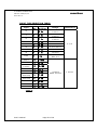
1
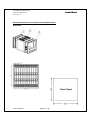
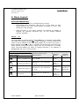
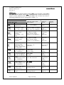
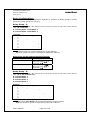
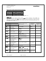
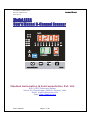
8-CHANNEL SCANNER-8208 masibus REF NO: m82A/om/101 Issue NO: 01 Model 8208 User’s Manual 8-Channel Scanner Masibus Automation & Instrumentation Pvt. Ltd. B/30, GIDC Electronics Estate, Sector-25, Gandhinagar-382044, Gujarat, India Email: [email protected] Web: www.masibus.com User’s Manual Page 1 of 36 8-CHANNEL SCANNER-8208 masibus REF NO: m82A/om/101 Issue NO: 01 Contents (1) Introduction (03) (2) Installation (05) (3) Hardware Specification Detail (08) (4) Front and Back Panel Description (11) (5) Key Function Description (13) (6) Menu Layout (14) (7) Relay Outputs (21) (8) Calibration Procedure (25) (9) Modbus Communication Detail (27) (10) Miscellaneous (34) User’s Manual Page 2 of 36 8-CHANNEL SCANNER-8208 masibus REF NO: m82A/om/101 Issue NO: 01 1. INTRODUCTION: Fo r e w ord Th an k you for pu rch a sin g 8208 universa l Scanner. This manu al de sc ri be s the b a sic f uncti on s an d ope rat i on me tho d s o f 82 08.Ple a se r e a d th r ou g h t h i s u se r ’ s m an u al ca re f u l ly b ef o r e u si n g t he p ro d u ct . No ti ce The c on te nt s of thi s ma n ua l a re subje ct t o ch an ge wi th out n oti ce as a r e su lt o f c on t in u i ng i m p r ove m e nt s t o t h e i n st r um e n t ’ s p er f o rm an ce an d fun ct i on s Every effort has been made to ensure accuracy in the preparation of this manual. Should any errors or omissions come to your attention, however, please inform MASIBUS Sales office or sales representative. Under no circumstances may the contents of this manual, in part or in whole, be transcribed or copied without our permission. Trademarks Our product names or brand names mentioned in this manual are the trademarks or registered trademarks of Masibus Automation and Instrumentation (P) Ltd. (herein after referred to as MASIBUS). Adobe, Acrobat, and Postscript are either registered trademarks or trademarks of Adobe Systems Incorporated. All other product names mentioned in this user's manual are trademarks or registered trademarks of their respective companies. Revision 1st Edition: July 2010. User’s Manual Page 3 of 36 8-CHANNEL SCANNER-8208 masibus REF NO: m82A/om/101 Issue NO: 01 Che c ki ng the Con te nts o f the P ackage Un p ack the b o x and che ck t he conten t s before u sing the produ ct. If the product is di f ferent f r o m t h at w h i ch y ou h av e o rd e re d , i f any p ar t s o r acc e s so r i e s a re mi s si ng, o r if t he p r o d u ct a p p e a r s t o b e damage d, contact your sa le s r e p r e se n t a ti ve . Product Ordering Code: The 8208 Scanner unit has a nameplate affixed to the one side of the enclosure. Check the model and suffix codes inscribed on the nameplate to confirm that the product received is that which was ordered. Model Suffix code Optional code Remarks List of Accessories The product is provided with the following accessories according to the model and suffix codes (see the table below). Check that none of them are missing or damaged. No Item name Part number User’s Manual Qty Remarks Page 4 of 36 8-CHANNEL SCANNER-8208 masibus REF NO: m82A/om/101 Issue NO: 01 2. INSTALLATION: How to Install: Mounting method: Panel mounting To install the controller select a location where: o o o o o o o o o no one may accidentally touch the terminals mechanical vibrations are minimal corrosive gas is minimal temperature can be maintained at about 25˚C to 35˚C and the fluctuation is minimal no direct radiant heat is present no magnetic disturbances are caused no wind blows against the terminal board no water splashed no flammable materials are around Turn off the power to the controller before installing it on the panel because there is a possibility of electric shock User’s Manual Page 5 of 36 8-CHANNEL SCANNER-8208 masibus REF NO: m82A/om/101 Issue NO: 01 External Dimensions and Panel Cutout Dimensions: Unit: mm User’s Manual Page 6 of 36 8-CHANNEL SCANNER-8208 masibus REF NO: m82A/om/101 Issue NO: 01 How to connect wires: Before carrying out wiring, turn off the power to the controller and check that the cables to be connected are not alive with a tester or the like because there is a possibility of electric shock. NOTE: o o o o o All wiring must confirm to appropriate standards of good practice and local codes and regulations. Wiring must be suitable for Voltage, Current and temperature rating of the system. Provide power from a single-phase instrument power supply. If there is a lot of noise in the power line, insert an insulating transformer into the primary side of the line and use a line filter on the secondary side. Do not place the primary and secondary power cables close to each other. For thermocouple input, use shielded compensating lead wires for wiring. For RTD input, use shielded wires that have low conductor resistance and cause no significant differences in resistance between the three wires. Do not connect Terminal NO – 13, 16,19,22,37,40,43,46 when thermocouple or linear input is selected. Use repeater after each set of 32 instruments connected in RS-485 Communication. Unused terminals should not be used as jumper points as they may be internally connected, which may cause damage to the unit. CAUTION: High voltage transients may occur when switching inductive loads such as some contactors or solenoid valves. Through the internal contacts, these transients may introduce disturbances which could affect the performance of the instrument. For this type of load it is highly recommended that a “sunbber” is connected across the normally open contact of the relay switching though load. The sunbber recommended consists of a series connected resistor/capacitor (typically 15nF/100 Ohms). A sunbber will also prolong the life of the relay contacts. A sunbber should also be connected across the output of a tric output to prevent false triggering under line transient conditions User’s Manual Page 7 of 36 8-CHANNEL SCANNER-8208 masibus REF NO: m82A/om/101 Issue NO: 01 3. Hardware Specification Detail: Input type: Universal input type Thermocouple, RTD, Millivolt, Voltage, Current INPUT types are software selectable. Applicable Standards: DIN (ITS-90) for Thermocouple and RTD T yp e R an ge E -2 00 t o 10 00 C J -2 00 t o 12 00 C K -2 00 t o 13 70 C T - 2 00 t o 40 0C B 4 5 0 t o 180 0 C R 0 t o 1 75 0C S 0 t o 1 75 0C N - 2 00 t o 13 0 0° C RTD - 1 99. 9 t o 85 0. 0 C A c c ur a cy +0.1% of instrument range + 1 digit for temperature equal to or higher than 0º C + 0.25% of instrument range + 1 digit for temperature below 0º C R e s ol u tio n +0.25% of instrument range + 1 digit(B,R,S TYPE TC) ( 1C B,R , S TYP E T C) 0 . 1 C + 0. 1% of instr ument r a nge + 1 digit 0 t o 7 5mV 0 t o 1 00 mv 0 . 4 t o 2V 0 to 2V 0- 20 mA* 4- 20 mA* 1 Count - 199 9 t o 99 99 0 to 5V 1 to 5V + 0. 1% of r ange + 1 d ig it 0 t o 1 0V -10 to 20 mV *For DC current input, 100 Ohms (0.1%, 25 ppm) shunt resistor must be connected externally. For DC current and Voltage input, Scaling is possible and decimal point is selectable. Sampling Period: 100mSec for TC and Linear Input, 200mSec for RTD Input. Resolution: 17-bit Burnout detection: Functions for TC, RTD, linear input signal. (It detects whether sensor is connected or not) ALL Relay output can be selected for Burnout Condition. i.e. Open sensor Up scale or Down Scale Measurement current (RTD): 1milli Ampere User’s Manual Page 8 of 36 8-CHANNEL SCANNER-8208 masibus REF NO: m82A/om/101 Issue NO: 01 Input Impedance: >1 Mohm for thermocouple/ mV/RTD/Volts inputs & 100 ohms for mAmp input. Noise Rejection Ratio: NMRR (Normal mode rejection ratio) > 40 dB (50/60 Hz) or more CMRR (Common mode rejection ratio) > 120 dB (50/60 Hz) or more Allowable wiring resistance for RTD: Maximum 15 ohms/wire (Conductor resistance between three wires should be equal). Retransmission Output: Number of outputs: 1 Process Value, Set point, or Control output can be selected as a Retransmission output. Output signal: 0-20 mA, 4-20 mA, 0-5 V, 1-5 V or 0-10 V DC. Voltage or current output can be selected through software and internal jumper settings. Load resistance: 500 ohms Max. Or less for current output. 3k or higher for voltage output Output accuracy: ±0.25% of Range Relay Contact Outputs: Number of outputs: 4 Output signal: Three terminals (NC, NO, and C) Relay Contact rating: 250 V AC or 30 V DC, 2A (resistive load) Operating/release time: <10 ms Communication: Communication Type: Half duplex/Asynchronous (RS-485) Communication Protocol: MODBUS RTU Baud rate, Parity and Stop bit are selectable form the key board. All parameters are Configurable through MODBUS. Connectable number of unit: 32 Communication error Detection: CRC Check Display Specifications: PV display: 4-digits, 7-segment, Red LEDs, character height of 0.56’’ Channel No. Display: 2-digits, 7-segment, Green LEDs, character height of 0.56’ Relay Group Display: 1-digits, 7-segment, Red LEDs, character height of 0.56’ St atu s indi cati ng l a mps: 1 6- Red LEDs for Alarms status, 4-Red LEDs for Relay status, 1-Red LED Manual mode status, 1-Red LED Fault status, 2-Green LEDS for Communication. User’s Manual Page 9 of 36 8-CHANNEL SCANNER-8208 masibus REF NO: m82A/om/101 Issue NO: 01 Power Supply Specifications: Power supply: Rated voltage of 85 to 260V AC at 50/60 Hz, Rated Dc voltage 120 to 360v / Rated voltage of 18 to 36V DC (Optional), Power consumption: Max. 15 VA Data backup: Non-volatile memory (can be written up to 100000 times) Withstanding Voltage: Between primary terminals* and secondary terminals** at least 1500VAC for 1 minute Between secondary terminals at least 600V AC for 1 minute Insulation resistance: 20Mohms or more at 500V DC *P rimary te rminals indicate powe r te rminal s and relay output terminals * * Se con d a r y te r mi n a l s ind i ca te an al og I/O sig n a l s, v ol t age pu l se out put , Co nt a ct input te r minal s, Re mote in put, RS 485 . Signal Isolations Specifications: PV input terminals(8 Channel input): Isolated from other input/output terminals. Retransmission output terminals (voltage/current): Not isolated from current or voltage outputs Isolated from other input/output terminals and internal circuit. Relay contact control output terminals: Isolated between contact output terminals and from other Input/output terminals and internal circuit. RS-485 Communication terminals: Isolated from other input/output terminals and internal circuit Power terminals: Isolated from other input/output terminals and internal circuit. Construction, Installation, and Wiring: Construction: Only the front panel is dust-proof Material: ABS resin and Polycarbonate Case color: Black Weight: About 0.5 kg or less Dimensions: 96 (W) x 96 (H) x 110 (depth from panel face) mm. Installation: Panel-mounting type. With Panel cutout dimensions: 92.5 + 0.8(W) x 92.5 + 0.8(H) mm Environmental Conditions: TEMPCO: FOR PV (Main input) less than 100ppm. FOR Retransmission less than 150ppm. Humidity: 30% to 95% RH (Non-Condensing) Instrument Warm-up Time: 30 minutes after power on Ambient temperature: 0 to 55°C User’s Manual Page 10 of 36 8-CHANNEL SCANNER-8208 masibus REF NO: m82A/om/101 Issue NO: 01 4. Front and Back Panel Description: FRONT PANEL Name of Part Process Value Display(DATA window) Channel No. Display (CHANNEL) Group No. Display (GROUP) Relay Indicator LED (RL1, RL2, RL3, & RL4) Alarm1(AL1) Indicator LEDs for Channel-1 to 8 Alarm1(AL2) Indicator LEDs for Channel-1 to 8 Auto/Manual Indicator LED (MAN) Communication Indicator LED(T1,R1 & T2,R2) User’s Manual Function Displays Process Value. Display Parameter Name When You Set Parameter. Displays Error Message When An Error Occurs. Displays Channel Number in run mode. Also it will display relay number (01 – 04) in set mode Displays Group Number for Relay Mapping. When Respective Relay LED Lits (In Red). When Alarm1 Occurs, Respective Alarm LED for Channel-1 to 8 will Lit (In Red). When Alarm2 Occurs, Respective Alarm LED for Channel-1 to 8 will Lit (In Red). If LED is on, it indicates Manual mode and if LED is off Auto Mode. When Communication on, two LEDs blink. Page 11 of 36 8-CHANNEL SCANNER-8208 masibus REF NO: m82A/om/101 Issue NO: 01 BACK PLATE CONNECTION DETAIL: mA V T/C 29 * RTD C 31 R L 3 NC 33 9 NC mA V T/C NO 32 * RTD C 34 10 C R L 2 R L 4 CH8 mA V T/C NO 35 NC 36 - * - mA V T/C * 45 18 mA V T/C * CH4 mA V T/C 47 * 19 20 21 RTD 46 48 CH3 44 16 17 RTD 43 + R L 1 CH7 15 CH2 41 42 RTD 40 + 7 C - * 22 23 + CH6 39 14 + RTD 28 30 6 12 NC - RX - mA V T/C 38 + 5 + RX * RTD 13 CH1 + + 27 4 mA V T/C 26 37 + D 3 E 11 NO CH5 RS485 - 8 NO RTD 25 + 2 N/ D - 1 L/+ - 24 * 100 Ohms 0.1% User’s Manual Page 12 of 36 8-CHANNEL SCANNER-8208 masibus REF NO: m82A/om/101 Issue NO: 01 5. KEY FUNCTION Description: MENU/ENTER KEY: It is used to enter in the sub menu (various levels) and save the parameters to nonvolatile memory, when user setting a proper data by Increment and shift key for parameter configuration. ESCAPE KEY: It is used to come out from any sub menu (various levels) to the run mode. INCREMENT KEY: It is used to increment the parameter for selection. Value of parameter can be incremented by pressing this key. When first time increment key pressed, DP (decimal point) in SV display blink, so user can modify the value with increment key. It is used to increment the value in particular digit. Value can be incremented from 0- 9 and from ‘9’ again it rollovers to ‘0’. SHIFT KEY/DECREMENT KEY: It is used to Shift the digit to set the parameter as describe in increment key when DP (decimal point) started to blink. Menu key is used to go forward to show next parameter and Shift key is used to go backward to show previous parameter. Also, in Run mode Shift key is used to give Acknowledge for ALARM and TRIP. AUTO/MANUAL KEY: It is used to switch between auto to manual mode and manual to auto mode. During manual mode Increment key is used to change channel number. User’s Manual Page 13 of 36 8-CHANNEL SCANNER-8208 masibus REF NO: m82A/om/101 Issue NO: 01 6. Menu Layout: RUN TIME INDICATION: Following parameters can view or change during run time. Immediately after powering, unit will run in Auto Mode. In auto mode channel will scan automatically according to scan time selection (1-250 second). Press A/M Key in run mode, Channel no scanning on display is stopped. By pressing increment key, we can change channel number manually. Le vel – 1: Pressing MENU key DATA window shows LVL1 (LvL1) message. Press MENU key again PV Display shows pWd (PWD) message, press increment key twice to select password and then press MENU key to enter into Level-1. DATA window shows SP.1 (SP.1) message and by pressing increment key, DATA window shows Set Point-1 Value Use Inc and shift key to modify value. OR press MENU key again to change Set-point 1 for Channel 2. ESCAPE KEY will use to come out SP.1 LEV EL 1 Parameter (DATA window) Symbol Name Sett ing name and descri pt ion pwd Level- 1 Passw ord 0 t o 999 9 0 000 - Sp .1 Ta rge t Set poin t- 1 SetP oi nt-1 f o r Channe l 1 t o 8. 01 0 0 ( for all 8 ch annel) - SP .2 Ta rge t Set poin t- 2 SetP oi nt-2 f o r Channe l 1 t o 8. 02 0 0( f or all 8 ch annel) Re l ay g rou p i s se le cte d 2 Hys Hystre sis Hy st re si s f or Ch anne l 1 t o 8. 00 0 2( f or all 8 ch annel) - (PWD) (SP.1) (SP.2) (HYS) User’s Manual Page 14 of 36 Def au lt v al ue S h ow s only if 8-CHANNEL SCANNER-8208 masibus REF NO: m82A/om/101 Issue NO: 01 LEV EL 2:Pressing MENU key DATA window shows LvL2 (LvL2) message. Press MENU key again DATA window shows pwd (PWD) message, press increment key twice to select password and then press MENU key to enter into Level-2. Following parameters can be configured in LEVEL – 2. LEV EL 2: P arame ter (D ATA Win dow) Symbol Name Le vel- 2 pwd P a ssw o rd (PWD) Sett ing name and de scri pt i on 0 t o 999 9 Def au lt v al ue Sh ow s o nl y i f 0 000 - K- TC(f o r all 8 ch annel) - inpt P V Inp ut T ype ( E , J , K, T E t c. ) F o ll ow Tab le 3( Input t ype for 1-8 ch annel) Pv .hi P r o ce ss v al ue r a nge h igh setting ( PV h ig h > P V l ow) Ran ge of the se n so r / - 1 9 9 9 t o 99 9 9 ( fo r line ar input type s)(1-8 Ch annel) 1 370(f o r all 8 ch annel) Pv .lo P r o ce ss v al ue r a nge l ow e r setting Ran ge of the se n so r / - 1 9 9 9 t o 99 9 9 ( fo r line ar input type s)(1-8 Ch annel) -2 00(f or all 8 ch annel) - 0 to 3(1 – 8 Ch anne l) 0 (f o r al l 8 ch annel) - nrml / flsf 0 : No r am l 1 :F a il S afe ALRM / TRiP 0:ALARM 1 :T R IP No rma l (f or all 4 Re l ay) Al arm(for all 4 Re l ay) 1 se co nd ( for all 4 Re l ay) Up S ca l e ( f or all 4 Re l ay) (inP.t) (PV.HI) (PV.LO) dp (dP) Rl .lg (rL.LG) Rl .fn (rL.Fn) De ci ma l Point S e tt ing Onl y a p p l i cab le f o r Line ar input ty pe i s se le cte d Re lay Logic( Ap plicable f o r 4- RELAY) Re lay F u n ct i on( A p pl i ca b le f o r 4-R EL AY ) Rl .dl Re lay Del ay ( Appl icable f o r 4- RELAY) 1 t o 9 9 se co n ds Rl .o .s Re lay O pen sen sor(Appli cable f o r 4- RELAY) up / DoWn 0 :DOW N 1 : UP (rL.dL) (rL.o.S) Rl .mp (rl.mp) Rl .tp (rl.tp) R e l ay m ap p i n g ( Ap p l i ca b le f o r 1 - 8 Channel ) Re lay G r oup T ype User’s Manual - - - - See Re la y Configurati on Re fe r Note:1 - See Re la y Configurati on Re fe r Note:2 - Page 15 of 36 8-CHANNEL SCANNER-8208 masibus REF NO: m82A/om/101 Issue NO: 01 Relay Configuration: Relay configuration depends on selection of Relay group i.e. Relay group 2 or Relay group 4 in Level-3. Relay Group - 2: If relay group – 2 is selected, there will be two group of relay. Each group has two relay. (G-1 and G-2). G-1 means RELAY 1 and RELAY 3 G-2 means RELAY 2 and RELAY 4 Example: CHANNEL NO 1 2 3 4 5 6 7 8 NONE G-1 G-2 Note: 1) Both Groups can not be selected for single Channel. 2) None means no group is selected for particular channel. Relay Type can be selected as shown below: Relay Group G–1 Relay Type High/ Very High (H-VH) or Very Low /Low (VL-L) or Low/High (L-H) High/ Very High (H-VH) or Very Low /Low (VL-L) or Low/High (L-H) G–2 Relay Group - 4: If relay group – 4 is selected, there will be four group of relay. Each group has one relay. (G-1, G-2, G-3 and G-4). G-1 means RELAY 1 G-2 means RELAY 2 G-3 means RELAY 3 G-4 means RELAY 4 Example: CHANNEL NO 1 2 3 4 5 6 7 8 NONE G-1 G-2 G-3 G-4 Note: 1) More than one Group can not be selected for single Channel. 2) None means no group is selected for particular Channel. User’s Manual Page 16 of 36 8-CHANNEL SCANNER-8208 masibus REF NO: m82A/om/101 Issue NO: 01 Relay Type can be selected as shown below: Relay Group G-1 G-2 G-3 G-4 Relay Type Low ON (L) or Low ON (L) or Low ON (L) or Low ON (L) or High High High High ON ON ON ON (H) (H) (H) (H) For relay functionality Refer Relay outputs (Chapter – 7). LEVEL – 3: Pressing MENU key DATA window shows LvL3 (LvL3) message. Press MENU key again DATA window shows pwd (PWD) message, press increment key twice to select password and then press MENU key to enter into Level-3.Following parameters can be configured in LEVEL – 3. LEVEL 3: Parameter (DATA Window) Symbol Name Level- 3 pwd Pa ssw o rd (PWD) Ch annel Skip sk i p/ Un ski p (skip) se le cti on. Sett ing name and descri pt ion Def au lt v al u e S h ow s only if 0 t o 999 9 0 000 - yes / no 0 : NO 1 :Y ES on / off 0 :O F F 1 :O N RGP .4 / rGP .2 0 : Re l ay G r oup -4 1 : Re l ay G r oup -2 0 (f o r al l 8 ch a nne l - 0 - 1 - 1 t o 250 se cond s 1 - yes / no 0 : NO 1 :Y ES 1 - 0 .0 t o 60 .0 Deg C 0 . 0 Deg C - U ni t ID 1 t o 247 1 (Baud) Communication Baud r ate Pr .St Pa rit y/ St op bi t se le cti on 9 600 / 1 9. 2K 0 :(96 00) – 9 600 bps 1 :(1 9.2K) –19. 2 Kbp s .n p .. S1 / P .nS .2 / P .o .s1 / P .ES .1 0 :(P . N. S.1 )- p ar ity n one-st o p bit - 1 Rl .lH (rL.LH) Rl .Gp Re l ay Latch (rL.GP) Re l ay G rou p SCAn Scan Time (SCAn) A.CJC\ (A.CJC) F.CJC (F.CJC) Sr.no (Sr.no) BAUd (Pr.St) Auto cold jun ct ion( Onl y ap pl i cab le fo r T C inpu t ty pe Fix col d jun ct ion( Onl y ap pl i cab le fo r T C inpu t ty pe User’s Manual Page 17 of 36 1 9.2k bp s No par ity /St op bit - 2 - 8-CHANNEL SCANNER-8208 masibus REF NO: m82A/om/101 Issue NO: 01 1 :(P . N. S.2 )- p ar ity n one - sto p bi t- 2 2 :(P .O. S.1 )- par ity od d -stop bit-1 3 :(P . E. S.1 )- p ari ty e ven - st op bi t- 1 TouT . (t.out) Ti meou t fo r di spl ay b ack to Run M o de RT .o .S (rt.o.s) Re t r a sm i s si o n O pe n se nso r Rt .tp (rt.tp) Re tra ns missi on Out put Type 1 0 t o 10 0 S e c on d s up / DoWn 0 :DOW N 1 : UP 0-20/4-20/ 0-5v/1-5v/ 0-10v 0 :(0- 20) – 0-20 mA 1 :(4- 20) – 4-20 mA 2 :( 0 - 5 ) – 0 – 5 vol t 3 :( 1 - 5 ) – 1 – 5 vol t 4:(0 – 10) - 0 - 10vol t Dir / rev 1 :( d i r ) 0 : (re v) Rt .dr (rt.dr) Re tra ns missi on di re ct ion Rt .CH Re tra ns missi on Ch annel 1 t o 8 c h anne l Rt .rd Re tra ns missi on Ch annel Va lue MAx / MIn 1 :(M ax ) 0 : (Min ) .Pwd S Pa ssw o rd Set password t o l o ck se le cte d le v e l (rt.CH) (rt.rd) (S.PWD) 0 t o 999 9 60 - 1 1 - 1 - 1 If Fix input type selected - 1 0 Cal i b r at ion :Pressing MENU key, DATA window shows CAL (CAL) message. Press MENU key again, DATA window shows pwd (PWD) message, press increment key twice to select password and then press MENU key to enter into Calibration. Ca l ib r a tion : Parameter (DATA Window) Symbol Name Sett ing name and descri pt ion pwd Passw ord 0 t o 999 9 0 000 - amb Ambient Ambien t adju stmen t - - The rmo cou pl e , Rtd and Li ne ar Ze ro Ca l ibt ri aon De pe nd ing on P V se ns or t ype se le cte d (PWD) (Amb) CAL .Z (CAL.Z) User’s Manual Page 18 of 36 Def au lt v al ue Sh ow s on ly if - 8-CHANNEL SCANNER-8208 masibus REF NO: m82A/om/101 Issue NO: 01 CAL .S (CAL.S) Rtr .Z (rtr.Z) Rtr .S (rtr.S) The rmo cou pl e , Rtd and Li ne ar Sp an Ca l ibt ri aon Re tra ns missi on vo lt age an d cur ren t Ze ro ca libration Re tra ns missi on vo lt age an d cur ren t Sp an ca libration De pe nd ing on P V se ns or t ype se le cte d - De pe nd ing on Re t ra sm i ssi o n t y p e se le cte d - De pe nd ing on Re t ra sm i ssi o n t y p e se le cte d - - Fa c t o r y R e s e t P ar a m et er s : P re ssi ng M E NU key, DATA w in do w show s F . RS T ( F. rS T) me ss age . Pr e s s MENU key again, DATA window show s p w d (PWD) me ssa ge, press In cre ment key tw ice t o se lect p assword and then pre ss M ENU key t o e nt e r i nt o F ac t o r y R e se t . Fa c to r y Re set Mod e: Parameter (DATA window) Symbol Name Pwd (Pwd) .def L (L.dEF) Sett ing name and descri pt ion Def au lt v al ue P a ssw o r d 0 to 9999 - - LOAD Default C AL\ PA RA \ all (CAL )\(PARA) \( AL L) CA L - Only cal ib ratio n se t to default v alue PARA - A ll p ara me ter s e x clu di n g ca l i b r at i on wi ll set t o de f aul t v al ue A LL-C a li b ra t i on and p ar a me te rs w i ll s et t o default v al ue - - User’s Manual Page 19 of 36 Sh ow s on ly if 8-CHANNEL SCANNER-8208 masibus REF NO: m82A/om/101 Issue NO: 01 INPUT TYPE SELECTION TABLE: I/ P NO T yp e Display E 1 E tc J 2 J tc K 3 K tc T S 4 5 6 7 T B R S N 8 n tc R TD 9 RTD 10 -10 .20 11 0-75 12 0-100 13 14 . 04-2 0-2V 15 4-20 16 0-20 17 18 19 0-5V 1-5V 0-10V Ty pe B R - 10 t o 20mV 0 t o 75mv 0 to 1 00 mV 0 . 4 to 2V 0 t o 2V 4 to 2 0 m amp 0 to 2 0 m amp 0 t o 5V 1 t o 5V 0 t o 1 0V tc tc tc tc R a nge - 200 to 1 000 C - 200 to 1 200 C - 200 to 1 370 C - 200 to 400 C 45 0 to 1 80 0 C 0. 1 °C 0 t o 175 0°C 0 t o 1 750 C - 200 to 1 300 °C - 1 9 9. 9 t o 8 50. 0 C -1 999 t o 9 9 99 Cou nt s Table 3: User’s Manual Res o l utio n Page 20 of 36 1 Count 8-CHANNEL SCANNER-8208 masibus REF NO: m82A/om/101 Issue NO: 01 7. Relay Outputs: Following function can be set for Relay outputs. Relay Logic (Direction): Relay Logic means Relay contact can be changed from NO – NC OR NC – NO. If relay logic is selected Normal, when Fault occur Relay contact will change from NC to NO. If relay logic is selected Fail Safe, when Fault occur Relay contact will change from NO to NC. Relay Function: Relay function can be selected as ALARM or TRIP. Relay Delay: A time delay can be provided for the actual output. Relay Open Sensor: Open sensor up scale or down scale can be selected for each relay output. Relay Mapping: Refer Menu layout LEVEL - 2 Relay Types: Various alarm operations are shown in the reference figure. (High, Low, Very High- High, Low-Very Low, High- Low) For relay types selection Refer Menu layout LEVEL – 2. User’s Manual Page 21 of 36 8-CHANNEL SCANNER-8208 masibus REF NO: m82A/om/101 Issue NO: 01 Relay logic table: ALARM 1 MOMEMTARY ALARM (when in abnormal condition ack not pressed) NORMAL ABNORMAL UP (O/S) DOWN (O/S) ACK ** NORMAL * ACK *** CONDITION ALARM LATCH LAMP YES HIGH FLASH FLASH OFF FLASH OFF ON ON OFF OFF OFF FLASH FLASH OFF OFF OFF RELAY OFF ON ON OFF OFF OFF LAMP FLASH OFF OFF FLASH OFF OFF ALARM LATCH LAMP NO TRIP OFF RELAY OFF OFF OFF RELAY OFF ALARM LATCH LAMP YES LOW RELAY OFF ALARM LATCH LAMP NO TRIP OFF OFF TRIP ON FLASH FLASH OFF ON OFF ON OFF OFF OFF FLASH OFF OFF ON OFF ON OFF OFF LAMP FLASH OFF OFF FLASH OFF OFF OFF RELAY OFF ON OFF OFF ON OFF FLASH OFF FLASH FLASH OFF OFF ON OFF ON OFF FLASH OFF FLASH OFF OFF RELAY OFF ON OFF ON OFF OFF LAMP FLASH OFF OFF FLASH OFF ON OFF OFF ON OFF ALARM LATCH LAMP NO OFF OFF FLASH RELAY OFF YES OFF RELAY OFF ALARM LATCH LAMP VLOW ON FLASH OFF OFF RELAY OFF ALARM AL2 MOMEMTARY ALARM (when in abnormal condition ack not pressed) CONDITION NORMAL ABNORMAL UP (O/S) DOWN (O/S) ACK ** NORMAL * ACK *** ALARM LATCH LAMP YES VHIGH FLASH FLASH OFF FLASH OFF ON ON OFF OFF OFF FLASH FLASH OFF OFF OFF RELAY OFF ON ON OFF OFF OFF LAMP FLASH OFF OFF FLASH OFF OFF ALARM LATCH LAMP NO TRIP OFF RELAY OFF OFF OFF RELAY OFF ALARM LATCH LAMP YES HIGH RELAY OFF ALARM LATCH LAMP NO TRIP OFF OFF TRIP OFF ON ON OFF OFF OFF FLASH OFF OFF OFF ON OFF OFF OFF LAMP FLASH OFF OFF FLASH OFF OFF OFF RELAY OFF ON OFF OFF ON OFF FLASH OFF FLASH FLASH OFF OFF ON OFF ON OFF FLASH OFF FLASH OFF OFF RELAY OFF ON OFF ON OFF OFF LAMP FLASH OFF OFF FLASH OFF ON OFF OFF ON OFF OFF OFF RELAY OFF User’s Manual ON FLASH ON ALARM LATCH LAMP NO OFF OFF FLASH RELAY OFF YES OFF FLASH RELAY OFF ALARM LATCH LAMP LOW ON FLASH Page 22 of 36 8-CHANNEL SCANNER-8208 masibus REF NO: m82A/om/101 Issue NO: 01 ALARM AL1 MAINTAINED ALARM (when in abnormal condition ack is pressed) CONDITION ALARM HIGH ALARM LOW ALARM DOWN UP (O/S) (O/S) ACK ** NORMAL * ACK *** LAMP OFF FLASH FLASH OFF STEADY STEADY OFF YES RELAY OFF ON ON OFF ON OFF OFF LATCH LAMP OFF FLASH FLASH OFF STEADY OFF OFF NO RELAY OFF ON ON OFF OFF OFF OFF LAMP OFF FLASH OFF OFF STEADY STEADY OFF OFF RELAY OFF ON OFF OFF ON ON LATCH LAMP OFF FLASH OFF FLASH STEADY STEADY OFF YES RELAY OFF ON OFF ON ON OFF OFF LATCH LAMP OFF FLASH OFF FLASH STEADY OFF OFF NO RELAY OFF ON OFF ON OFF OFF OFF LAMP OFF FLASH OFF OFF STEADY STEADY OFF TRIP VLOW ABNORMAL LATCH TRIP ALARM NORMAL RELAY OFF ON OFF OFF ON ON OFF LAMP OFF FLASH OFF FLASH STEADY STEADY OFF YES RELAY OFF ON OFF ON ON OFF OFF LATCH LAMP OFF FLASH OFF FLASH STEADY OFF OFF RELAY OFF ON OFF ON OFF OFF OFF ALARM LATCH ALARM NO TRIP LAMP OFF FLASH OFF OFF STEADY STEADY OFF RELAY OFF ON OFF OFF ON ON OFF ABNORMAL DOWN UP (O/S) (O/S) ACK ** NORMAL * ACK *** ALARM AL2 MAINTAINED ALARM (when in abnormal condition ack is pressed) CONDITION NORMAL ALARM VHIGH ALARM LATCH LAMP OFF FLASH FLASH OFF STEADY STEADY OFF YES RELAY OFF ON ON OFF ON OFF OFF LATCH LAMP OFF FLASH FLASH OFF STEADY OFF OFF NO RELAY OFF ON ON OFF OFF OFF OFF LAMP OFF FLASH OFF OFF STEADY STEADY OFF TRIP ALARM HIGH ALARM RELAY OFF ON OFF OFF ON ON OFF LAMP OFF FLASH FLASH OFF STEADY STEADY OFF YES RELAY OFF ON ON OFF ON OFF OFF LATCH LAMP OFF FLASH FLASH OFF STEADY OFF OFF NO RELAY OFF ON ON OFF OFF OFF OFF LATCH TRIP ALARM LOW ALARM LAMP OFF FLASH OFF OFF STEADY STEADY OFF RELAY OFF ON OFF OFF ON ON OFF LATCH LAMP OFF FLASH OFF FLASH STEADY STEADY OFF YES RELAY OFF ON OFF ON ON OFF OFF LATCH LAMP OFF FLASH OFF FLASH STEADY OFF OFF NO RELAY OFF ON OFF ON OFF OFF OFF LAMP OFF FLASH OFF OFF STEADY STEADY OFF RELAY OFF ON OFF OFF ON ON OFF TRIP User’s Manual Page 23 of 36 8-CHANNEL SCANNER-8208 masibus REF NO: m82A/om/101 Issue NO: 01 Notes : * means normal condition after abnormal has occurred ** means ack pressed in abnormal condition *** means ack pressed in normal condition after abnormal has already occurred. Upon pressing Shift/Decrement key for 3 seconds, acknowledgement will be given for alarm and trip relay in abnormal condition. Alarm Latch function applicable only for ALARM, there is no affect when TRIP Selected as a relay function LEVEL – 2. Basic RELAY Function: RELAY GROUP - 4 User’s Manual Page 24 of 36 8-CHANNEL SCANNER-8208 masibus REF NO: m82A/om/101 Issue NO: 01 RELAY GROUP - 2 User’s Manual Page 25 of 36 8-CHANNEL SCANNER-8208 masibus REF NO: m82A/om/101 Issue NO: 01 8. Calibration Procedure:Calibration is provided for ambient temperature, PV sensor input, Retransmission output. First select the calibration function as described below and then follow the procedure depending on the parameter to be calibrated. The sequences of parameters that will be available for calibration are listed below: Ambient temperature adjustment PV Sensor input Retransmission output (calibration for voltage or current) Ambient temperature adjustment:This menu will come up only if; the input sensor selected is Thermocouple type. PV display shows Amb (Ambient temperature adjusts). PV display shows ambient temperature measured by the controller and by applying old calibration data. DP of last digit will blink to indicate that the value can be changed. Use Inc/Shift key to adjust it to desired value. Once the desired value set and press MENU key, the blinking DP will go off to indicate that the value has been registered. The controller will automatically save all the new calculations. Ambient temperature adjustment is over. Press MENU key to calibrate other parameters or press Escape key to come out to normal operation. PV input sensor calibration:When user enters in calibration menu, PV display shows message ZERO (Thermocouple/Linear/RTD) for sensor input span calibration for Thermocouple Linear input and RTD type. Feed sensor input using a calibrator, such that process value is close to lower range value. Note: The controller allows the user to calibrate sensor’s input anywhere in the range, but it is recommended that it should be calibrate the input at points close to lower and upper range values. DP of last digit will blink to indicate that the value can be changed. Use Inc/Shift key to correct the displayed reading to the desired process value and press MENU key. The controller will display message wait (wait) in the PV display to indicate that it is doing the necessary calculations. When the calculations are over, the new calibration values are stored automatically. PV shows the message SPAN (calibration SPAN). PV display shows process value corresponding to input sensor value with old calibration data. Feed sensor input using a calibrator, such that process value is close to sensor’s upper range value. Use Inc/Shift key to arrive at the desired process value. Press MENU key to register the changes. The controller will display message wait (wait) in the PV display to indicate that it is doing the necessary calculations. Depending on the situation, this process may take few seconds to calibrate. Zero and Span calibration is over User’s Manual Page 26 of 36 8-CHANNEL SCANNER-8208 masibus REF NO: m82A/om/101 Issue NO: 01 In case, the controller cannot complete the calibration due to any reason, it will hold previous calibration parameters. Calibration for input sensor is over. Retransmission output calibration (Voltage/current output):Press set key repeatedly, till PV display shows message rtr.Z (retransmission output zero calibration). SV display shows the value being outputted on Retransmission output terminals. Measure the value using a highly accurate digital multi meter. Use Inc/Shift key to correct the displayed reading to the measured value. Press ENT key. The controller will store zero calibration value. Press MENU key to calibrate retransmission output span calibration menu. PV shows the message rtr.S (retransmission output span calibration). SV display shows the value being outputted on retransmission output terminals. Measure the value. Use Inc/Shift key to correct the displayed reading to the measured value. Press ENT key. When the calculations are over, the new calibration values are stored automatically. Calibration for Retransmission output is over. Press MENU key to calibrate other parameters or press Escape key to come out to normal operation. Group Calibration Detail:Group NO 1 2 3 4 5 Input type E,J,K,T,N,075mv,0-100mv Pt-100(RTD) B,R,S,-10 to 20mv 0-2V,0.4-2V,420mamp,020mamp 0-10V,0-5v,1-5V Calibration for input Either of any input Specific input Either of any input Either of any input Either of any input NOTE: If you calibrate any input from any group i.e. I/P E-TC from Group – 1 than calibration is not required for other input types from Group-1. User’s Manual Page 27 of 36 8-CHANNEL SCANNER-8208 masibus REF NO: m82A/om/101 Issue NO: 01 9. Communication: T he M O D B U S Commu n i ca t i ons pr o to co l as RS -4 85 or RS- 232 inte rf ace m o du le i s i n stal le d . O n l y R T U mo d e i s sup p or t e d. D at a i s t r ansm it te d a s 8 -b it b i n a ry byt e s w it h 1 s t a r t b it , 1/2 st op bit and op tional parity ch ecking (None, Even, Odd ). Bau d rate may be se t t o 9 600 and 19200 . Function code use for Modbus: CODE NAME Function 01 Write Coil Status Use to write output and input status 03 Read Holding registers Use to read PV for 8-channels 04 Read input registers Use to read programmable registers 05 Force Single Coil Use to set or reset the coil 06 Preset Single register Use to write programmable register Exception responses for Modbus: Code Name Meaning 01 ILLEGAL FUNCTION The function code received in the query is not an allowable action for the slave. If a Poll Program Complete command was issued, this code indicates that no program function preceded it. 02 ILLEGAL DATA ADDRESS The data address received in the query is not an allowable address for the slave 03 ILLEGAL DATA VALUE 06 Slave Device Busy A value contained in the query data field is not an allowable value for the slave When Master device write some parameters to Slave device If slave device busy it will send 06 code to indicate slave device is busy. Modbus Parameter Details for Holding Register: Modbus values for OPEN, OVER, UNDER and SKIP Conditions: SR.NO. Parameter 1 2 3 4 5 6 7 8 9 PV Channel PV Channel PV Channel PV Channel PV Channel PV Channel PV Channel PV Channel Ambient User’s Manual -1 –2 –3 –4 –5 –6 –7 –8 Absolute Address 30001 30002 30003 30004 30005 30006 30007 30008 30009 Parameter Type INT INT INT INT INT INT INT INT INT Page 28 of 36 Min Value - Max Value - Access Type R R R R R R R R R 8-CHANNEL SCANNER-8208 masibus REF NO: m82A/om/101 Issue NO: 01 SR. NO. 1 2 3 4 Parameter Value Open sensor Over reading Under reading Skip Channel 32767 32766 32765 32764 Modbus Parameter Details for Holding Register: SR. NO. Parameter Absolute Address Parameter Type Min Value Max Value Access Type 1 2 3 4 5 6 7 8 9 10 11 12 13 14 15 16 17 18 19 20 21 22 23 24 25 26 27 28 29 30 31 32 33 34 35 36 37 38 39 40 SP.1 CH – 1 SP.1 CH – 2 SP.1 CH – 3 SP.1 CH – 4 SP.1 CH – 5 SP.1 CH – 6 SP.1 CH – 7 SP.1 CH – 8 SP.2 CH- 1 SP.2 CH- 2 SP.2 CH- 3 SP.2 CH- 4 SP.2 CH- 5 SP.2 CH- 6 SP.2 CH- 7 SP.2 CH- 8 HYS CH – 1 HYS CH – 2 HYS CH – 3 HYS CH – 4 HYS CH – 5 HYS CH – 6 HYS CH – 7 HYS CH – 8 INPUT TYPE CH INPUT TYPE CH INPUT TYPE CH INPUT TYPE CH INPUT TYPE CH INPUT TYPE CH INPUT TYPE CH INPUT TYPE CH SPAN CH - 1 SPAN CH - 2 SPAN CH - 3 SPAN CH - 4 SPAN CH - 5 SPAN CH - 6 SPAN CH - 7 SPAN CH - 8 40001 40002 40003 40004 40005 40006 40007 40008 40009 40010 40011 40012 40013 40014 40015 40016 40017 40018 40019 40020 40021 40022 40023 40024 40025 40026 40027 40028 40029 40030 40031 40032 40033 40034 40035 40036 40037 40038 40039 40040 INT INT INT INT INT INT INT INT INT INT INT INT INT INT INT INT INT INT INT INT INT INT INT INT INT INT INT INT INT INT INT INT INT INT INT INT INT INT INT INT Refer Refer Refer Refer Refer Refer Refer Refer Refer Refer Refer Refer Refer Refer Refer Refer 1 1 1 1 1 1 1 1 Refer Refer Refer Refer Refer Refer Refer Refer Refer Refer Refer Refer Refer Refer Refer Refer Refer Refer Refer Refer Refer Refer Refer Refer Refer Refer Refer Refer Refer Refer Refer Refer 250 250 250 250 250 250 250 250 Refer Refer Refer Refer Refer Refer Refer Refer Refer Refer Refer Refer Refer Refer Refer Refer R/W R/W R/W R/W R/W R/W R/W R/W R/W R/W R/W R/W R/W R/W R/W R/W R/W R/W R/W R/W R/W R/W R/W R/W R/W R/W R/W R/W R/W R/W R/W R/W R/W R/W R/W R/W R/W R/W R/W R/W User’s Manual - 1 2 3 4 5 6 7 8 Page 29 of 36 T-1 T-1 T-1 T-1 T-1 T-1 T-1 T-1 T-1 T-1 T-1 T-1 T-1 T-1 T-1 T-1 T-1 T-1 T-1 T-1 T-1 T-1 T-1 T-1 T-1 T-1 T-1 T-1 T-1 T-1 T-1 T-1 T-1 T-1 T-1 T-1 T-1 T-1 T-1 T-1 T-1 T-1 T-1 T-1 T-1 T-1 T-1 T-1 T-1 T-1 T-1 T-1 T-1 T-1 T-1 T-1 T-1 T-1 T-1 T-1 T-1 T-1 T-1 T-1 NOTE 8-CHANNEL SCANNER-8208 masibus REF NO: m82A/om/101 Issue NO: 01 SR. NO. Parameter Absolute Address Parameter Type Min Value 41 42 43 44 45 46 47 48 49 50 51 52 53 54 55 56 57 58 59 60 61 62 63 64 65 66 67 68 69 70 71 72 73 74 75 76 77 78 79 80 81 82 83 84 85 86 87 88 89 90 91 92 ZERO CH - 1 ZERO CH - 2 ZERO CH - 3 ZERO CH - 4 ZERO CH - 5 ZERO CH - 6 ZERO CH - 7 ZERO CH - 8 Decimal Point CH - 1 Decimal Point CH - 2 Decimal Point CH - 3 Decimal Point CH - 4 Decimal Point CH - 5 Decimal Point CH - 6 Decimal Point CH - 7 Decimal Point CH - 8 RLY-Logic.1 RLY-Logic.2 RLY-Logic.3 RLY-Logic.4 RLY-Function.1 RLY-Function.2 RLY-Function.3 RLY-Function.4 RLY-Delay.1 RLY-Delay.2 RLY-Delay.3 RLY-Delay.4 RLY-OpenSensor.1 RLY-OpenSensor.2 RLY-OpenSensor.3 RLY-OpenSensor.4 RLY-Map CH - 1 RLY-Map CH - 2 RLY-Map CH - 3 RLY-Map CH - 4 RLY-Map CH - 5 RLY-Map CH - 6 RLY-Map CH - 7 RLY-Map CH - 8 RLY-Type.1 RLY-Type.2 RLY-Type.3 RLY-Type.4 SKIP-Channel CH - 1 SKIP-Channel CH - 2 SKIP-Channel CH - 3 SKIP-Channel CH - 4 SKIP-Channel CH - 5 SKIP-Channel CH - 6 SKIP-Channel CH - 7 SKIP-Channel CH - 8 40041 40042 40043 40044 40045 40046 40047 40048 40049 40050 40051 40052 40053 40054 40055 40056 40057 40058 40059 40060 40061 40062 40063 40064 40065 40066 40067 40068 40069 40070 40071 40072 40073 40074 40075 40076 40077 40078 40079 40080 40081 40082 40083 40084 40085 40086 40087 40088 40089 40090 40091 40092 INT INT INT INT INT INT INT INT INT INT INT INT INT INT INT INT INT INT INT INT INT INT INT INT INT INT INT INT INT INT INT INT INT INT INT INT INT INT INT INT INT INT INT INT INT INT INT INT INT INT INT INT Refer Refer Refer Refer Refer Refer Refer Refer 0 0 0 0 0 0 0 0 0 0 0 0 0 0 0 0 1 1 1 1 0 0 0 0 0 0 0 0 0 0 0 0 0 0 0 0 0 0 0 0 0 0 0 0 User’s Manual Page 30 of 36 T-1 T-1 T-1 T-1 T-1 T-1 T-1 T-1 Max Value Access Type Refer Refer Refer Refer Refer Refer Refer Refer 3 3 3 3 3 3 3 3 1 1 1 1 1 1 1 1 99 99 99 99 1 1 1 1 4 4 2/4 2/4 2/4 2/4 2/4 2/4 2/4 2/4 2/4 2/4 1 1 1 1 1 1 1 1 R/W R/W R/W R/W R/W R/W R/W R/W R/W R/W R/W R/W R/W R/W R/W R/W R/W R/W R/W R/W R/W R/W R/W R/W R/W R/W R/W R/W R/W R/W R/W R/W R/W R/W R/W R/W R/W R/W R/W R/W R/W R/W R/W R/W R/W R/W R/W R/W R/W R/W R/W R/W T-1 T-1 T-1 T-1 T-1 T-1 T-1 T-1 NOTE 8-CHANNEL SCANNER-8208 masibus REF NO: m82A/om/101 Issue NO: 01 SR. Parameter NO. Absolute Address Parameter Type Min Value Max Value Access Type 93 94 95 96 97 98 99 100 101 102 103 104 105 106 107 108 109 110 111 112 113 114 40093 40094 40095 40096 40097 40098 40099 40100 40101 40102 40103 40104 40105 40106 40107 40108 40109 40110 40111 40112 40113 40114 INT INT INT INT INT INT INT INT INT INT INT INT INT INT INT INT INT INT INT INT INT 0 0 1 0 0 1 0 0 10 0 0 0 0 0 0 0 0 0 0 0 0 1 1 1 250 1 600 247 1 3 60 1 4 1 1 1 1 1 1 1 1 1 1 8 R/W R/W R/W R/W R/W R/W R/W R/W R/W R/W R/W R/W R/W R/W R/W R/W R/W R/W R/W R/W R/W R/W 40115 INT 0 9999 R/W 115 116 117 118 RLY Latch RLY Group Scan Rate Auto CJC Fix CJC Machine ID Baud Rate Parity/Stop Bit Timeout PV Scale Retransmission Retransmission Type Retransmission Direction Retransmission CH - 1 Retransmission CH - 2 Retransmission CH - 3 Retransmission CH - 4 Retransmission CH - 5 Retransmission CH - 6 Retransmission CH - 7 Retransmission CH - 8 Retransmission Value Retransmission Channel selection Password Future use Future use Future use NOTE: 1) For fix input type, Modbus allow to write Input type, Span, Zero and Decimal point for only First channel. For other channels Input type, Span, Zero and Decimal point set according to First channel. 2) For Retransmission output, Modbus address 40105 to 40113 is applicable only for Fix input type. User’s Manual Page 31 of 36 NOTE 8-CHANNEL SCANNER-8208 masibus REF NO: m82A/om/101 Issue NO: 01 Modbus Parameter Details for Read Output Status Register: SR. NO. Parameter Absolute Address Parameter Type Access Type 1 2 3 4 5 6 7 8 9 10 11 12 13 14 15 16 17 18 19 20 21 22 23 24 Alarm.1 Channel-1 Alarm.1 Channel-2 Alarm.1 Channel-3 Alarm.1 Channel-4 Alarm.1 Channel-5 Alarm.1 Channel-6 Alarm.1 Channel-7 Alarm.1 Channel-8 Alarm.2 Channel-1 Alarm.2 Channel-2 Alarm.2 Channel-3 Alarm.2 Channel-4 Alarm.2 Channel-5 Alarm.2 Channel-6 Alarm.2 Channel-7 Alarm.2 Channel-8 RELAY STATUS-1 RELAY STATUS-2 RELAY STATUS-3 RELAY STATUS-4 Auto/Manual Mode Acknowledge For Relay Unused Unused 1 2 3 4 5 6 7 8 9 10 11 12 13 14 15 16 17 18 19 20 21 22 - BIT BIT BIT BIT BIT BIT BIT BIT BIT BIT BIT BIT BIT BIT BIT BIT BIT BIT BIT BIT BIT BIT - R R R R R R R R R R R R R R R R R R R R R/W W - NOTE: For Auto/Manual Mode, to set Manual mode bit value = 1 and to set Auto mode bit value = 0. For Acknowledgement function, to give acknowledge for relay bit value = 1. User’s Manual Page 32 of 36 8-CHANNEL SCANNER-8208 masibus REF NO: m82A/om/101 Issue NO: 01 INPUT TYPE SELECTION TABLE: Input Type I/P no Type Display Zero Span Resolution E 1 -200 1000 0.1°C J 2 -200 1200 0.1°C K 3 -200 1370 0.1°C T 4 -200 400 0.1°C B 5 450 1800 1°C R 6 0 1750 1°C S 7 0 1750 1°C N 8 0 1300 0.1°C RTD 9 -199.9 850.0 0.1°C -10 to 20mv 10 -1999 9999 0-75mV 11 -1999 9999 0-100mV 12 -1999 9999 0 to 2V 13 -1999 9999 0.4 to 2V 14 E tc J tc K tc T tc B tc R tc S tc n tc RTD -10 .20 0-75 0-100 0-2V .4-2V 0 -1999 9999 4 TO 20mAmp 0 to 20 mAmp 0-5V 15 -1999 9999 -1999 9999 -1999 9999 1-5V 18 -1999 9999 0-10V 19 -1999 9999 16 17 4-20 0-20 0-5V 1-5V 0-10V Relay Function: Relay Direction: Modbus Index 0 1 Modbus Index 0 1 Parameter Value Normal Fail Safe Relay Selection for Open sensor: Modbus Index 0 1 Parameter Value Down Up Relay Group 2 Channel selections: Modbus Index Parameter Value 0 None 1 G - 1(RELAY 1 & 3) 2 G – 2(RELAY 2 & 4) Relay Group -2 Type selection: Modbus Index 0 User’s Manual 1 Count Parameter Value Alarm Trip Relay Group - 4 selections: Modbus Index Parameter Value 0 None 1 G-1(RELAY – 1) 2 G-2(RELAY – 2) 3 G-3(RELAY – 3) 4 G-4(RELAY – 4) Relay Group - 4 Type selections: Parameter Value High/Very High Page 33 of 36 Modbus Index 0 1 Parameter Value Low ON High ON 8-CHANNEL SCANNER-8208 masibus REF NO: m82A/om/101 Issue NO: 01 1 2 Low/Very Low High/LOW Relay per Group Selection: Relay Latch selection: Modbus Index 0 1 Modbus Index 0 1 Parameter Value OFF ON Baud Rate Selection for Communication: Modbus Index 0 1 Parameter Value Relay Per Group – 1 Relay Per Group – 2 Parity/Stop Bit Selection: Parameter Value 9600bps 19.2kpbs Modbus Index 0 1 2 3 Parameter Value Parity-None/Stop Bit - 1 Parity-None/Stop Bit - 2 Parity Odd/Stop Bit – 1 Parity Even/Stop Bit – 1 Retransmission OPEN sensor Scale: Modbus Index 0 1 Parameter Value Down Up Retransmission Type selection: Modbus Index 0 1 2 3 4 Retransmission Direction: Modbus Index 0 1 Parameter Value Reverse Direct Retransmission Value: Modbus Index 0 1 User’s Manual Parameter Value Minimum Maximum Page 34 of 36 Parameter Value 0 – 20mAmp 4 – 20mAmp 0 – 5V 1 – 5V 0 – 10V 8-CHANNEL SCANNER-8208 masibus REF NO: m82A/om/101 Issue NO: 01 10. MISCELLENIOUS PV INPUT STATUS DISPLAY DURING BURNOUT CONDITION: Input type Display Message TC-E OPEN(oPEn) TC-J OPEN TC-K OPEN TC-T OPEN TC-N OPEN TC-B OPEN TC-R OPEN TC-S OPEN PT 100(RTD) OPEN 0-10V DC OPEN 0 to 5V DC OPEN 1 to 5V DC OPEN 0 to 2V DC OPEN 0.4 to 2V DC OPEN 0 to 20mAmp PV LOW 4 to 20mAmp PV LOW -10 to 20mV DC OPEN 0-100mV DC OPEN 0-75mV DC OPEN Table 1 Note: If set PV_low/PV_high for input type is less then maximum value of zero and span for then process value will display readings above 5% of display range, then after it will show oVER/UnDR (OVER/UNDER) message until value crosses maximum value of Sensor range. Process value greater then maximum value of zero/span then display will show oPEn (OPEN) message. Retransmission o/p will follow 5% of display range and then it will give fixed o/p depending up on OPEN sensor selection. In case of linear inputs scaling is applied then during OPEN sensor condition it may not show oPEn (OPEN) message instead it will show either oVER/UnDR (OVER/UNDER). User’s Manual Page 35 of 36 8-CHANNEL SCANNER-8208 masibus REF NO: m82A/om/101 Issue NO: 01 RETRAMISSION OUTPUT TABLE FOR OPEN /OVER /UNDER CONDITION: RETRASMISSION VARIABLE SCALE ACTION OPEN OVER UNDER ERROR 4-20mamp PV UP DIR 20.8 20.8 3.2 - PV DOWN REV 20.8 3.2 20.8 - PV UP REV 3.2 3.2 20.8 - PV DOWN DIR 3.2 20.8 3.2 - Table 2 NOTE: - 1) For Retransmission output type 0-20mamp, 0-10v, 1-5v and 0-5v also applicable according to above table. 2) Also, 0-20mamp, 0-10v and 0-5v minimum output value will be 0mamp and 0v respectively. 3) For Mix input type any one channel can be selected as Retrasmission output. For Fix input type more than one channel can be selected for Retrasmission, but output depends on Maximum reading or Minimum reading from the no of channel Retrasmission output Maximum and Minimum can be selected from Level-3. User’s Manual Page 36 of 36