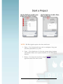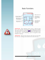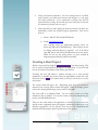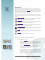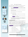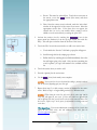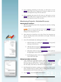
1
4 Version .0 LEGEND BRANDS Dri-Plan - Mobile Documentation System Dri-Plan User Guide For Version 4.0 – June 2015 LEGEND BRANDS Dri-Plan Mobile Documentation System LBG Distributing, Inc. 2014-2015 15180 Josh Wilson Road Burlington, WA 98233 800-932-3030 www.legendbrands.net Updated: May 27th 2015 © LBG Distributing, Inc. 2014 – Updated 2/18/15 Table of Contents Basic System Overview............................................................ 1 Icon Reference Guide .............................................................. 3 Quick Start Guide ..................................................................... 4 Log In to Mobile App ................................................................ 9 Syncing Mobile App ................................................................. 9 Creating a New Project .......................................................... 10 Building Project Layers (Floors, Zones, Rooms) ........................... 11 Sketching Rooms .......................................................................... 13 Water Migration Markers ............................................................... 15 Assigning Wall Properties ............................................................. 16 Assigning Room Detail (Class, Category, etc.) ............................. 17 Taking Room Photos..................................................................... 18 Room Notes .................................................................................. 19 Adding Equipment ......................................................................... 21 Adding Monitoring locations .......................................................... 23 Equipment Table: Reviewing Assignments .................................. 26 Monitoring Tables: Reviewing Data ............................................. 27 Assigning Services ........................................................................ 28 Monitoring Projects: Suggested Process ............................... 30 Best Practice / Process ................................................................. 30 Monitoring Projects: Detailed Process ................................... 32 Selecting Project to Monitor .......................................................... 32 Editing Project Notes and Details .................................................. 32 Adding New Service Date ............................................................. 33 Reviewing Equipment Changes .................................................... 34 Reviewing Monitoring Data ........................................................... 35 Removing Equipment .................................................................... 36 Adding Equipment ......................................................................... 37 Verifying Complete Monitoring ...................................................... 38 D R I - P L A N V E R S I O N M O B I L E 3 . 2 – D O C U M E N T A T I O N N O V E M B E R 2 0 1 4 Basic System Overview This section provides a basic overview of Dri-Plan and suggested Apple devices for use with the iOS application. T he Dri-Plan mobile documentation system is a highly adaptable solution designed to satisfy the needs for fast, reliable and professional recording and reporting of project data in the water damage restoration field. It utilizes iOS based mobile device technology and a unique ‘graphics driven’ user interface to greatly reduce the amount of time needed to capture daily monitoring information. Dri-Plan is based on two main components; (1) the iOS app for iPhones® and iPads® allows data to be captured in the field, while (2) the web portal at www.drieazapp.com allows for reporting, administration and customization of the software. Data captured in the field is stored on your iOS device, then pushed up to the internet when you choose. This eliminates the need for an internet connection while in the field – something that simply cannot be relied upon. Once synced, the data is then available from the web for reporting. Simple and practical, but complete and professional. (1) - iOS Application: Dri-Plan The mobile Dri-Plan mobile app is available from the Apple Store (Dri-Plan). It is compatible with any iOS device that can run version 7.0 or more recent firmware. It is suggested that the device used have a camera to allow you to use all of Dri-Plan’s photo and scanning capabilities. It is also suggested that an iPad or iPad Mini be used for initial project setup, as room sketch functions are much easier to perform on a larger screen. Smaller devices can be used, however, for all functions of Dri-Plan’s mobile app. This includes iPhones and iPod Touch devices. The smaller devices are ideal for follow up monitoring visits, where sketch is not needed. The iOS application provides functionality to perform several types of documentation. These include: • High level project description, such as name, address, notes, insurer contact, etc. 1 Click for Overview Video • Defining project areas, such as floors, drying zones and rooms • Creating dimensioned room sketches • Assigning project variables such as Class and Category of loss • Viewing equipment minimum requirements for airmovers and LGR dehumidification systems • Assigning equipment by simple ‘drag and drop’ onto the dimensioned sketch, selecting from a wide range of equipment types • Assigning and tracking moisture monitoring locations • Tracking Temperature and Humidity readings • Assigning service items by room and date • Photo documentation, along with notes and annotation (2) - Website: www.drieazapp.com The Dri-Plan website allows you to review current and past projects, customize the content of the iOS app, run reports and manage your users. With a fully customizable color scheme and logo, the site can be truly made your own. Customization to the site carries through to your reports, too! Projects can also be initiated from the website, allowing fast entry of high level project details such as: • Project name • Customer, and contact information • Project Address • Project notes • Insurer Contact and Claim information 2 Icon Reference Guide Refer to this chart to identify references to ‘ ’ within the Dri-Plan iOS app: 3 Quick Start Guide This section provides a basic startup and operation guide. Detailed instructions can be found in the appropriate sections later in this guide. If you are familiar with the basic navigation used by most iOS (Apple) device apps, you may be able to use Dri-Plan with very little instruction. The ‘Important Icon Reference Guide’ on the previous page, along with the following quick start guides will give you what you need to get going in DriPlan quickly. Due to the very important nature of some of the features in the mobile app, however, we strongly suggest you review at least the following sections of the more detailed user guide: 1. Sketching Rooms 2. Adding Service Dates 3. Verifying Complete Monitoring Thank you for using Dri-Plan. Let us know how we can help you achieve success in the Cleaning and Restoration industry! The Legend Brands Team 800-932-3030 www.legendbrands.net 4 IMPORTANT: The Sync function is a critical element to Dri-Plan. Data is stored locally on the iOS device, and is not available to the Dri-Plan website until it is synced. There are functions provided under the maintenance screen to allow you to ‘fully sync’ if a data connection issue is experienced. Access these options by using the ‘ ’ icon (wrench) at the bottom of your project, floor, zone or room list. 5 NOTE: Dri-Plan organizes projects into three main layers: 1. Floors – Use for horizontal layers, such as crawlspaces, living areas (First floor, Second floor, etc.), attics 2. Zones – Use to break areas of a floor into separate drying chambers when needed. If there are no separate chambers, use the same name as the floor. 3. Rooms – You access the room list by using the ‘ upper left corner of the ‘canvas’ screen. 6 ’ button in the IMPORTANT: Always note the active room and active date. Changes made will be applied to what is noted as active. Change the active date by touching the active date window. Change the active room by touching the room name on the canvas, or by using the ‘ ’ button in the upper left corner. NOTE: Double click icons on screen to open windows for reviewing and editing data. Red dots next to icons indicate data is missing. NOTE: Main icons in the top menu bar can be toggled on and off. Touch once and the icon will become ‘blue.’ Touch again to toggle the mode off, and the icon becomes black. 7 IMPORTANT: When monitoring a project, ensure you ‘add’ the current date as a new service date. This is done by either touching the date window and using the ‘plus’ icon, or by using the ‘ ’ button and selecting the room from the room list. You will be prompted to ‘add’ the current date if it does not already exist. See the ‘Monitoring’ section of this guide for more information on this step. IMPORTANT: Always be aware of the active ‘date’ and ‘room’ in the upper left of the screen. All changes made will affect the date and room shown. 8 Log In to Mobile App Upon launching the iPad or iPhone app (or after other steps that result in logging out), you will be presented with the ‘log in’ screen. 1. Enter your user name, typically your email address 2. Enter your password 3. Click ‘Submit’ If using the application in free ‘demo’ mode, simply click the ‘demo’ option (in red). Also included on this screen is the application version number. Presently, the most recent version of the application is version 4.0, released in June of 2015. Check the Apple Store for updates and new releases, or visit www.dri-plan.com. There is an ‘information’ icon also included on this screen, which provides a brief description of the Dri-Plan mobile application. Syncing Mobile App After login, you will be prompted to ‘ ’ your app. It is important especially after your first login to sync, so data specific to your account can populate inside of Dri-Plan. This requires an internet connection, either by WiFi or cellular access. After your initial sync, return to the sync function often (at least once daily), to ensure data on your device is regularly updated and available on the web application for reporting. The ‘ arrows). ’ icon is located in the lower left corner of the screen (circular Note : If you are using a cellular data-enabled device, you can set your preference for cellular syncing under the maintenance and settings area of the app (wrench icon). In some cases, you may experience a connection loss or other issue during sync. If this occurs, an error message will display after synchronization. Check the data on via the web application at www.drieazapp.com to ensure your data has synced properly. If for any reason it has not, take the following actions: 1. Run a ‘Full Sync’ accessed through the ‘ ’ icon (wrench) – verify data has transferred to the web application. If not, move to step the next step. 9 2. Verify your internet connection. Go to the settings area on your iPad, and/or launch your Safari web browser and navigate to a web page and verify connectivity. If no connection is present, this must be corrected before syncing. Re-run full sync once connection is restored. If connection is present, move to step 3. 3. After using full sync, and verifying an internet connection, if data is not transferring, contact our technical support department. This can be done by: a. Phone: 800-932-3030 (8AM-5PM Pacific) b. Email: [email protected] Also available under the maintenance/settings screen are ‘Reset App DB’ and ‘Full DB Backup.’ These options are for use during technical support, if required. Use of the ‘Reset App DB’ option will erase all Dri-Plan data from your device. Please do not use this setting unless you have verified all important project data has synced successfully. Creating a New Project Initiate a new project by using the ‘ ’ icon after syncing. This icon is used in several functions throughout the application. It can be found next to the ‘Projects’ list header (folder with a plus symbol). Touching this icon will launch a window allowing you to enter specific information to describe the project. Enter the appropriate content into each field, then use the ‘ ’ icon (check mark) at the top of the form to save the new project. The location field will open a list. Depending upon how your account is structured, one or more office locations will appear. If this list is empty, please refer to the ‘Syncing Mobile App’ section earlier in this guide. The notes field is an unlimited field. You can enter as much or as little information here as needed. You can also return to this form later during the project, and add additional notes. There are also other areas in the application to add notes, such as notes for specific rooms, equipment items, photographs, monitoring locations, etc. It is therefore suggested to use the ‘project’ notes area just for information that describes the entire project and not specific areas of the project. 10 Building Project Layers (Floors, Zones, Rooms) Dri-Plan organizes projects into three layers. There’s no limit to how many items you can add to each layer, allowing Dri-Plan to handle anything from a single bathroom to a multi-story high-rise. Use the ‘ ’ icon to create new layers: 1. Floors: The floor level is exactly as it appears. Use this first level to add a ‘floor’ for each horizontal section of the property. Do not forget to add a ‘floor’ for crawlspaces and attics if they are a part of the scope of work. 2. Zones: The zone level is used to break floors into separate drying chambers. The application will provide suggested dehumidification sizing by zone, and will break certain reports and graphs into zones. Use this function only when your project has distinctly separate ‘air spaces’ in a single floor, such as with apartment buildings, commercial suites, etc. If only one zone exists, you will still have to ‘add’ it – just name it the same as the floor name. 3. Rooms: Exactly as the name implies, these are the areas in a zone divided by walls but not isolated by solid barriers. Bedrooms, hallways, closets, kitchens etc in the same residential space, for example. Project Layers: 11 Build out your project layers using the following process: 1. Touch the project name in the ‘project’ list 2. Add Floors a. The screen should now show ‘Floors’ at the top of the list b. Use the ‘ add a floor ’ icon (folder with plus sign) to c. Enter the floor name, then use the ‘ to save ’ icon (check mark) d. Repeat for each floor that needs to be added 3. Add Zones a. Touch the floor name you are working on b. The screen should show ‘Zones’ at the top of the list c. Use the ‘ add a zone ’ icon (folder with plus sign) to d. Enter the zone name, then use ‘ ’ icon to save e. Repeat for each zone that needs to be added to the floor 4. Add Rooms a. Touch the zone name you are working on b. The screen should now show ‘Rooms’ at the top of the list c. Use the ‘ add a room ’ icon (folder with plus sign) to d. Enter the room name, then use the ‘ ’ icon to save e. Repeat for each room that needs to be added, beginning with step ‘d’ from this process 5. Touch any room name to enter that room and begin adding details, such as a sketch of the room, photos, notes, etc. 12 Sketching Rooms The sketch function within Dri-Plan will allow you to generate a twodimensional layout of each room, and overlay those rooms within each zone. This provides a general sketch for the room and the drying zone. The sketch function is triggered by selecting the ‘ ’ icon from the top menu bar on the ‘canvas’ view (ruler/pencil icon). Once activated, the sketch mode icon will become blue, and a new set of icons will appear on the right side of the screen. In order from top to bottom, these icons are: : This icon allows you to quickly create a rectangular shape with the approximate room length and width : Allows a corner to be added to a wall, and one section of the wall to be moved in or out to create an offset : Allows a corner to be added to a wall, and the corner to be moved in or out to add shape to the wall the area of migration : Allows water marks to be added to indicate : Allows the last change made to walls or water markers to be ‘undone’ : Allows a water marker to be ‘removed’ Sketch a room for your project using the following process: 1. Draw a rough sketch to start: a. Touch the ‘ ’ mode icon in the upper menu bar (pencil/ruler icon). The icon should turn blue, and the sketch tools should appear along the right hand side of the screen b. Touch the ‘ ’ tool (box with a ‘plus’ symbol). It is the first/top tool in the sketch tool bar window. The tool icon will become blue when active c. Touch the upper left area of the blue canvas/screen, then drag your finger diagonally toward the lower right corner of the canvas. As you do so, a room will be drawn on your screen. Watch the dimensions as you drag your finger across the 13 screen, and move your finger until the dimensions are either exactly or close to the actual dimensions of the room. d. Remove your finger from the screen. The room will ‘snap’ to the screen dimensions (usually become smaller on screen), however the dimension will not change. 2. Adjust dimensions if required: a. Touch any of the four walls of the rough room, and the wall will become ‘active.’ You will notice two red squares (corners of wall) and one blue square (center of wall) i. Drag the blue square to move a wall section to adjust room width or length ii. Drag a red square to adjust a corner position (if corners are not 90 degrees) iii. Use the ‘ ’ button if the change made was in error, or if it resulted in an undesired dimension or shape change iv. Touch another wall if needed to make further adjustments v. Repeat until the overall length and width of the room is as needed 3. Add offsets/insets a. Touch the ‘ ’ tool (box with arrow and offset). It is the second tool from the top of the tool bar. The icon will turn blue when active. b. Touch the wall assembly where an offset needs to be added. The wall will ‘split’ where touched, and two blue boxes will appear. NOTE: If the split/break does not appear in the correct location on the wall, it can be adjusted later. Continue building the offset, then adjust after the offset has been added. NOTE: If necessary, use the ‘undo’ button to remove the break from the wall. NOTE: It may be necessary to ‘zoom in’ to the wall to allow for easier editing. This is done by placing two fingers on the 14 screen, and spreading your fingers apart. You may also place one finger on the screen and slide it across the screen to ‘move’ the room. c. Drag one of the blue boxes to create an inset or offset in the wall. Once complete, turn the tool ‘off’ by touching it again. The icon will turn black/dark grey. If additional offsets are needed, touch the offset tool again, and repeat from step ‘a’ above. 4. Add additional corners a. To add architectural features to the wall such as bay windows, odd angle corners, etc., use the ‘ ’ tool. It is the third tool from the top of the tool bar (corner with a ‘plus’ symbol). The tool will become blue when active. b. Touch a wall assembly where a corner is desired. A red box will appear. c. Drag the red box in our out to add the additional corner. d. Repeat as needed to add additional corners. 5. Exit Sketch Mode a. Exit sketch mode by touching the ‘ ’ icon in the upper menu bar (pencil/ruler). The icon will change from blue (active) to black (inactive). NOTE: There are additional steps that can be done while in sketch mode if more detail is needed for your scope. These include Indicating water migration and assigning wall properties The sections that follow address these steps. If you wish to take these steps, do not exit sketch mode (or, re-activate sketch mode at a later time to complete these steps when appropriate). Water Migration Markers The water migration markers allow you to indicate the affected area within a room or space. The markers will default to ‘blue’ when placed on screen. However, later in the application, you can assign the ‘Category’ of water loss. This assignment will alter the appearance of the water markers: • Category 1: Blue (Not significantly contaminated) • Category 2: Grey (Significant contamination) 15 • Category 3: Black (Grossly Contaminated) Water migration markers are added during the ‘sketch’ process. While in Sketch mode, add water migration markers using the following process: 1. Activate the ‘ ’ tool in the Sketch Tool window (water droplet). It is the fourth tool from the top. The icon will turn blue when active. 2. Touch the area(s) within the room or area that are wet, and an icon will be placed in that location 3. Continue touching the screen to add additional markers 4. Move or Delete markers: a. Place your finger on any marker in the room, then drag the marker to move it b. Double click any marker in the room, then touch the ‘ ’ icon (‘X’) to delete it. 5. Once complete, turn the water migration tool off by touching the tool icon (water droplet) in the sketch toolbar. The icon will change from blue to black, indicating it is no longer active. Assigning Wall Properties The wall properties menu will allow you to make several assignments and modifications to the walls within the room that has been drawn. It is important to first sketch the room before assigning properties, as some properties can be ‘copied’ to all walls. If properties are assigned before sketching is complete, new walls will not carry the same assignments. The wall properties menu is activated while in sketch mode by touching the ‘ ’ icon in the upper menu (immediately to the right of the sketch mode icon, circle containing the letter ‘i’). In this menu, you can: • Assign a wall height • Define the wall construction • Adjust a wall length (feet/inches) • Adjust the affected linear feet of all (feet/inches) Use the wall properties menu by following this process: 16 1. While in sketch mode (and after sketching the room or space), activate the wall properties menu by touching the ‘ ’ icon in the upper menu bar. The icon will become blue, indicating it is active. 2. Next, touch the wall for which you need to edit properties NOTE: If no wall is selected, the form will populate with the information for the last wall selected. To ensure you are editing the correct wall, verify the correct wall is selected in the canvas by looking for the red boxes (ends of wall) and blue box (center of wall). 3. Adjust the properties as needed, then use the ‘ at the top of the form to save the properties ’ icon (check mark) NOTE: After adjusting the height of a wall, you can use the icon to the right of the wall height to ‘copy’ the information to all walls in that room. 4. If needed, touch another wall in the room while the wall properties menu is open, and continue editing until the appropriate properties are set for all walls. Us the ‘ ’ icon (check mark) to save before changing walls. Assigning Room Detail (Class, Category, etc.) The room details screen allows you to view and edit several properties for the active room, and to view important equipment calculations for the space. You can also access definitions for water Category and Class per the ANSI/IICRC S500 Standard and Reference Guide. Access the Room Detail screen by touching the ‘ ’ icon in the upper menu bar while in the Canvas View. The icon will change from black to blue, indicating it is active. Ensure you are not in the sketch mode, as this icon is used for wall properties when sketch is active. If the sketch mode is active, touch the ‘ ’ icon (pencil/ruler) to deactivate it. Then, touch the ‘Information’ icon to open room details. From here, you can view and edit: • Water Category • Water Class • Room humidity and temperature (for the current date and time) • Assign a floor type • View total Affected Linear Feet (for the active room) 17 • View total Square Feet (for the active room) • View minimum suggested airmovers (for the active room) • View total minimum dehumidification (in Pints/Day at an AHAM rating, for LGRS, for the active Zone) While this screen is open, edit or modify any of the fields as needed, then use the ‘ ’ icon to save your changes. You can review important definitions to assist with assignment by touching the help icon (question mark). Touch anywhere outside of the popup help window to close the screen. NOTE: You can enter and modify humidity and temperature readings in other areas of the application. See ‘Reviewing Monitoring Data’ later in this guide. Taking Room Photos The photo tool in Dri-Plan allows you to utilize the camera on your iOS device to capture an unlimited number of images on each project. Each image is automatically tagged with the project, room and date information for your project. The photo tool also includes an annotation feature to allow you to capture notes and comments for each photo, allowing for a very complete but simple photo documentation system. Access the photo documentation tool by touching the photo tool icon in the upper menu bar (photo symbol). When active, the photo tool icon will become blue. A screen will open at from the bottom of your device. Near the right hand side of this screen, you will see a photo icon. Touch this icon to launch the in-app camera and follow the on-screen instructions: Take a photo: • Use the ‘capture’ button (white circle) in the lower center area to take a photo Adjust camera settings: • Double tap any area of the image to auto-adjust lighting and focus for that area of the image • Double tap and slide your finger up or down to manually adjust lighting • Touch the flash icon (if device is equipped with a flash) to adjust flash settings 18 • Touch the ‘switch camera’ icon (circular arrows inside camera outline) to change from the front camera to the back camera of your device Once an image is taken, select ‘retake’ or ‘use photo.’ Once accepted (use photo), it will appear on the list in this same screen. All project photos can be viewed from this screen. Scroll through photos by swiping up or down on the list. You can also edit notes for photos by touching the ‘ ’ icon (pencil) to the right of each image. Save the note by touching the ‘ ’ icon (red disk) to the right of the note. To enlarge an image, touch the photo. When finished viewing, touch anywhere on the screen (away from the image). NOTE: If you are using a cellular enabled device, you can adjust the settings for ‘sync photos over cellular’ under the settings area of the app. You can find this setting by using the ‘ ’ icon (wrench) at the bottom of your Room, Zone, Floor or Project list screen. Room Notes Dri-Plan includes several note taking features to allow for thorough documentation of project details. Room notes are specific to each room and are saved by both the room name and service date. If needed, several separate notes can be taken for the same room on the same service date. There are several other areas for capturing notes. These include: • Project notes: Access from the main project list screen. These notes can be edited at any point during the project, and are included in most reports on the main title page for the project. • Room notes: Access these at any time from the main canvas screen by touching the ‘ ’ icon (notebook/pencil) in the upper menu bar. These notes will only be included in the Correspondence report. Notes are date specific, and several notes can be captured on the same date. • Equipment Notes: Access these notes by double clicking an equipment icon in the main canvas. These notes are date specific, and will appear in the Equipment report and Correspondence report. • Photo Notes/Annotations: Access these notes by launching the photo tool from the upper menu bar. Notes are date and photo specific, and will only appear in the photo report. • Metering Notes: Access by double clicking on any monitoring point on the canvas. Notes are specific to the monitoring location, and are 19 not date specific. They are intended to describe the monitoring method and/or material type and assembly construction. For information on other note types in Dri-Plan, refer to the appropriate section in this user guide. Room notes can be captured using the following process: 1. Verify you have selected the appropriate room. Check the ‘active room’ noted in the upper left area of the screen. If necessary, change to the correct room by either touching the room name on the canvas, or by using the ‘ ’ button in the upper left (blue arrow), then selecting the room from the list. 2. Activate the room ‘ ’ icon by touching the icon in the upper menu bar (notepad/pencil). The icon will become blue indicating it is active. A window will open from the bottom of the screen. 3. Use the ‘Plus’ symbol to add a new note. The note area will turn to a light blue/green, with the phrase ‘Please write new note here.’ Touch this area of the screen, and your device keyboard will open. Begin typing. NOTE: If using an external keyboard, the device keyboard will not open. NOTE: If using a cellular enabled device, or if there is an active internet connection by Wi-Fi, you can use the ‘annotate’ feature by touching the microphone immediately to the left of the keyboard. 4. Once the note is complete, use the ‘ ’ icon (check mark). The keyboard will close, and your note will appear on the left as the current date. You can touch this date to view the note a. Edit existing note: Touch the date that represents the note – it will become visible in the notes window. Use the ‘ ’ icon to step into the note and edit. Use the ‘Save’ icon to save once complete. b. Delete existing note: Touch the date that represents the note – it will become visible in the notes window. Touch the ‘ ’ icon (X) to delete it. c. Add another note: Use the ‘plus’ icon to add as many notes as needed. Remember, the note will save as the current date and to the active room (look at active room window in upper left). To save a note to a different room, leave the notes area and 20 select the appropriate room, then re-launch the note taking tool. Adding Equipment The equipment management system in Dri-Plan includes several features to allow you to fully define your equipment use on each project. Fields are included to show codes and descriptions associated with common estimating systems. Notes fields allow you to track daily adjustments made to each equipment item, or other statuses like ‘equipment was turned off.’ The equipment features are also very visual, with icons and graphics that let you see and communicate exactly what was used and how it was used. Simple indicators let you know at a glance that information is missing, and Dri-Plan even stores an image for every service date – so you can refer back and review exact equipment placement for every day, of every room, on every job. Equipment is added to your Dri-Plan project after the sketch process has been completed. It is important to verify, before adding equipment that the appropriate room has been selected and is ‘active.’ Each default equipment item that appears in this tray is pre-populated with information related to Xactimate codes and descriptions – a time saver for users of Xactware software. Once added to the room, equipment icons will appear with a small red dot. This dot indicates that additional information can be added to the item, such as an asset ID number, notes, etc. This is a feature that allows you to quickly scan a room and identify where information is missing or can be added. Some information when added the first day of the project will be retained, and not need to be re-entered on follow up monitoring visits (items that do not change, such as the AHAM rating for a dehumidifier). Information that is likely to change, however, will not carry from one date to the next, and can be ‘re-entered’ each day (performance from dehumidifiers and notes, in particular). Add equipment to a room using the following process: 1. Verify the correct room is ‘active’ by looking in the upper left corner of the screen. The room name should appear in this area. The screen should also include a blue background, and the active room should have red walls, while any other rooms in that zone should appear with grey walls. 21 a. If the wrong room name is appearing in the upper left, select the correct room by touching the room name on the canvas, or by using the ‘ ’ button in the upper left (blue arrow), then selecting the correct room from the list. b. When adding equipment during the Monitoring process (after job setup, on a follow-up visit to the project), also verify the correct service date is appearing in the upper left. This field will be blank until one or more assets are added to the project. 2. Activate the Equipment Tray. This is done by touching the icon (box with three lines) in the darker grey main menu bar at the top of the screen. 3. Scroll through the equipment icons to find the appropriate item. Swipe up or down (iPad), or use the arrows at the top and bottom of the tray (iPhone, iPod) to scroll. 4. Drag the icon out of the tray and into the active room. Place your finger on the icon in the tray, then drag your finger across the screen until the icon is in the correct location. Then remove your finger from the screen. 5. Add additional details to the item. Double click the icon you placed into the active room. A window will open from the bottom of the screen. Here, you can add information to the icon. Use the ‘ ’ icon once complete a. Serial/Asset #: You can manually type the asset number, select it from a list (created by your administrator), or use the ‘barcode scan’ feature to capture it from the device (barcode or QR code needed). b. Code: This is pre-populated for all default items. It is the Xactware code for the item. c. Dehumidifier Specific Items: i. Temperature: Enter the outlet temperature for that date from the dehumidifier ii. Humidity: Enter the outlet relative humidity for that date from the dehumidifier iii. GPP: Calculated humidity ratio in grains per pound of dry air 22 iv. AHAM Rating: Enter the AHAM rating for the dehumidifier used d. Notes: Add a note about how or why the equipment is being used. This is date specific, so additional notes can be added on follow up monitoring visits as needed. e. Sel, Cat, Description, UM, Activity: These are pre-populated for all default items, and are related to the Xactware code. f. Field: This is related to the type of item in Dri-Plan. Most items will appear with ‘standard.’ 6. Add additional equipment by repeating this process from step 3. Once complete for the active room, select the next room by referring to step 1. 7. Close the equipment tray by touching the again. The blue background will turn off, and the tray will close icon NOTE: You can remove equipment from the active room by either: Touching the ‘ ’ icon (‘X’) next to the equipment tray icon (it will turn red) then double clicking the item you with to delete (turn the mode off by touching the ‘Delete’ icon again), or Double clicking the equipment item you wish to delete, then touching the ‘ ’ icon (‘X’) in the popup window that appears Web App Note: Your account administrator can manage the list of equipment that appear on your mobile device, and add additional items from the www.drieazapp.com web portal. Adding Monitoring locations Monitoring locations provide the ability to assign a specific area where meters will be used to measure and track the drying progress of various materials. Each assigned location will receive a unique identification number, and allow you to track: • The meter value, daily • The surface temperature, daily • Moisture wicking (walls, etc.), daily 23 • The surface type • Relative location of the monitoring spot • Dry standard (or drying goal) In addition to these, additional information can be added to record a description of the material and the meter being used. These details are accessed under the Moisture Monitoring Table (see Monitoring Tables section, later in this guide). Monitoring locations appear as a ‘target’ icon in the canvas. As a default, they appear in black and white – however they will colorize once data has been added: • Red: • Yellow: • Green: Approx. 20% higher/wetter (or more) than the drying goal Approx. 10-20% higher than the drying goal Within 10% of the drying goal, or lower As with equipment, the monitoring icon will appear with a red dot if information is missing. The colorization and the red dot allow you to quickly scan a room and determine the status of drying, and if additional information can be recorded. Add a monitoring location, and associated information, using the following process: 1. Verify the correct room is ‘active’ by looking in the upper left corner of the screen. The room name should appear in this area. The screen should also include a blue background, and the active room should have red walls, while any other rooms in that zone should appear with grey walls. a. If the wrong room name is appearing in the upper left, select the correct room by touching the room name on the canvas, or by using the ‘ ’ button in the upper left (blue arrow), then selecting the correct room from the list. b. When adding equipment during the Monitoring process (after job setup, on a follow-up visit to the project), also verify the correct service date is appearing in the upper left. This field will be blank until one or more assets are added to the project. 24 2. Activate the Equipment Tray. This is done by touching the icon for the (box with three lines) in the darker grey main menu bar at the top of the screen. 3. Scroll through the equipment icons to find the monitoring location icon (target shape). Swipe up or down (iPad), or use the arrows at the top and bottom of the tray (iPhone, iPod) to scroll. 4. Drag the monitoring location icon from the tray and into the active room. This is done by placing your finger on the icon in the tray, then dragging your finger across the screen until the icon is in the correct location. Once it is in place, remove your finger from the screen. 5. Add additional details to the item. Double click the icon you placed into the active room. A window will open from the bottom of the screen. Here, you can add information to the icon. Use the ‘ ’ icon once complete. a. Moisture Reading: Enter the value from the moisture meter. This can be captured daily b. Surface Temperature: Enter the temperature of the surface of the material. This can be captured daily c. Moisture Wicking: Enter the height or distance the moisture has wicked through or up the material (for example, enter ‘6’ for 6” up a wall). This can be captured daily d. Surface type: Select from the list the most appropriate surface type. If the surface type does not appear in this list, it can be manually typed in the ‘Monitoring Table’ View (covered later in this guide) e. Relative Location: Describe the location in the room (e.g., ‘Northwest corner’) f. Dry Standard: Enter the normal or target moisture level 6. Add additional monitoring locations by repeating from step 4 above. 7. Add monitoring locations to other rooms by referring to step 1 above. 25 Equipment Table: Reviewing Assignments Dri-Plan offers a table-view format for equipment assignments to allow for faster review of daily equipment utilization. This view provides the ability to see the total quantity of each equipment type used by day. It also offers the ability to edit certain information, such as the Asset ID, Code and Notes for each item. Use this view to quickly review total equipment utilization, or to review and make further changes to equipment notes. Access and use the Equipment Table view by: 1. Activate the table by using the ‘ ’ icon in the main menu bar at the top of the screen (Figure of equipment, to the right of the Notes icon). The icon will become blue, and a table view will open from the bottom of the screen. 2. Scroll up and down through the equipment by swiping up or down on the table. All equipment installed in the current, active Zone will appear in the list (all rooms in that zone) 3. Scroll through dates (when multiple dates have been recorded) by swiping left or right across the date row. Four dates will appear at a time 4. Expand an equipment type to view and edit data for that item by clicking the ‘plus’ sign at the left of the row, immediately beside the equipment type name a. Touch the ‘ ’ icon (pencil) to activate edit mode. Fields that can be edited will become blue b. Touch the field you wish to edit, then type c. Touch the ‘ ’ icon (red disk) to the right once complete 5. Close the expanded view for an item by touching the ‘minus’ symbol to the immediate left of the equipment name at the left side of the screen. 6. Toggle the equipment table view off by again touching the ‘ ’ icon in the upper menu bar. It will return to dark grey, and the table window will close. 26 Monitoring Tables: Reviewing Data Two tables exist for reviewing and editing monitoring data: the atmospheric monitoring table (psychrometric readings) and the moisture monitoring table (moisture content readings). Both tables provide a means to quickly review changes in monitoring data, and to allow for quickly editing that data. These views should be used during the initial project setup to verify that all monitoring data has been gathered. It is also a critical part of the ongoing monitoring process, discussed later in this guide. Atmospheric Monitoring Table 1. Activate the atmospheric monitoring table by touching the ‘ ’ icon in the upper menu bar (meter shape, immediately left of the target shaped icon) 2. Change the date range in the table by swiping left or right across the date row 3. Scroll through areas by swiping up or down on the table. Each room in the active zone is listed, including an area for ‘Outside.’ 4. Edit the data in the table by touching the ‘ ’ icon (pencil) on the far right. The fields that can be edited will become blue. 5. Use the ‘ ’ icon (red disk) to the far right once complete. NOTE: When using this table during follow up monitoring visits (after initial setup), adding data to an empty field may create a new service date for the room. Please see ‘Adding New Service Date’ for a discussion on this topic. NOTE: the value for gpp (humidity ratio in grains per pound of dry air) will auto-calculate. Moisture Monitoring Table 1. Activate the moisture monitoring table by touching ‘ ’ the icon in the upper menu bar (target shape) 2. Change the date range in the table by swiping left or right across the date row 3. Scroll through monitoring locations by swiping up or down on the table. All monitoring locations for the active zone will appear in this table 4. Expand a monitoring location for more detail by touching the ‘plus’ icon to the immediate left of the monitoring location ID 27 5. Edit the data in the table by touching the ‘ ’ icon (pencil) on the far right. The fields that can be edited will become blue. Use the ‘ ’ icon (red disk) to the far right once complete a. Meter Values: The first four fields are the area in which the meter value can be recorded, by date b. Surface Type: The type of surface being monitored (example: Floor, Ceiling) c. S. Temp: Surface temp for the current, active service date (see active date in the upper left corner of your screen) d. Goal: The dry standard or drying goal e. Wicking: The amount of wicking up or across the surface or material, for the current service date f. Meter Note: Description of how the meter is being used, and/or what type of meter g. Material Note: Description of the material or assembly type being monitored NOTE: When using this table during follow up monitoring visits (after initial setup), adding data to an empty field may create a new service date for the room. Please see ‘Adding New Service Date’ for a discussion on this topic. Assigning Services The services component of Dri-Plan allows you to capture all billable services rendered during the restoration process. As a default, the available services within Dri-Plan are the water category items with Xactware. However, this list can be modified using the Dri-Plan web application. Services assigned are tracked by room and date. Associated data needed to produce a full and complete scope is also captured, such as the quantity, unit of measure, Xactimate code/description, etc. Assign services to your Dri-Plan project using the following process: 1. From the Canvas View, verify the correct room and date are active by checking the upper left corner of the screen. If necessary, change the room or date: 28 a. Room: This must be selected first. Touch the room name on the canvas, or use the ‘ ’ button (blue arrow) and select the appropriate room b. Date: Once the correct room is selected, touch the ‘active date’ window in the upper left of the canvas view screen. Select the appropriate service date. If the date does not appear, the current date (as set in your mobile device settings) can be added as a new service date by touching the ‘plus’ icon 2. Activate the services view by touching the ‘ ’ icon in the upper menu bar (farthest icon in the top right corner, box with five lines). This will open a window from the bottom of the screen 3. Touch the ‘Plus’ icon in the new window to add a new service item a. Touch inside the “Service:” field and a popup list will appear. b. Scroll through this list by swiping up or down c. Refine the list by touching the text field immediately above the list and begin typing a key word. Only services containing the word or phrase you type will remain in the available services list 4. Touch the service item you wish to add 5. Provide a quantity for the service item 6. Use the ‘ ’ icon (check mark) once complete NOTE: You may need to close your keyboard after adding a quantity in order to view the check icon, depending upon your device type 7. Repeat from step 3 to add as many services as required to the active room. Refer to step 1 to begin adding services to a different room. NOTE: When viewing the services list, only services for the ‘active room’ and the ‘active date’ will appear on your screen. If services were added to a different room and/or different service date, you will need to select the correct room and date to view those services. Refer to step 1 in this process for information on selecting rooms and service dates. Web App Note: Your account administrator can manage the list of services that appear on your mobile device, and add additional service items from the www.drieazapp.com web portal. 29 Monitoring Projects: Suggested Process In addition to capturing initial project setup details, Dri-Plan provides a unique and highly adaptable system for ongoing daily monitoring. This process can be completed in several ways, however the following process is suggested for the most efficient and complete daily monitoring: Best Practice / Process 1. Select the appropriate project 2. Select the first Floor to be monitored 3. Select the first Zone to be monitored 4. Select the first Room to be monitored IMPORTANT: you will be prompted by a popup window, asking you to either ‘Add Today’s Date’ or ‘Continue.’ Select ‘Add Today’s Date.’ This will add the current date from your mobile device settings as a new Service Date. More information on this topic can be found under IMPORTANT: Dri-Plan will automatically refer to the previous service date for the selected room and copy all equipment placement and monitoring location data. Ensure you complete this process daily for any active projects. 5. You will be presented with a view showing the selected room as ‘active’ on the canvas (walls in red). Icons representing the location of the previous day’s equipment and monitoring locations will appear, accompanied by a ‘red dot.’ The dot indicates that the item needs to be monitored and updated. 6. Double tap each icon, and supply the current-date data. Use the ‘ ’ icon (check mark) to save after updating each item: a. Update notes for equipment items b. Add temperature and humidity data for dehumidifiers c. Add current moisture content, surface temperature and wicking information for monitoring points d. Use the ‘ ’ icon to delete equipment items that are being removed on that service date 30 7. As necessary, relocate items within the room if item has been moved to a new location by placing your finger on the icon and ‘dragging’ it to its new location NOTE: It is suggested that you not move moisture monitoring points. If a new location for monitoring is needed, add a new monitoring icon. Refer to the section titled ‘Adding Monitoring Locations’ to review this process 8. As needed, activate the room ‘ ’ mode using the icon in the upper menu bar (notepad and pencil). Add and save the room note 9. As needed, activate the ‘ ’ mode using the icon in the upper menu bar (photograph icon). Add and annotate photos 10. Repeat from step 6 for each icon in the active room, until the ‘red dots’ are removed from all icons 11. Select the next room to be monitored using the ‘ ’ button in the upper left corner of the screen (blue arrow). Touch the room name to be monitored. Repeat from step 4 of this process for each room in the current zone IMPORTANT: You will again be prompted to ‘Add New Service Date’ upon selecting each room. This step must be completed for each room before beginning to update monitoring data. To ensure you have added the service date, check the date in the ‘active date window’ in the upper left corner of your screen. If this date does not reflect the current date, touch the window. A list of available service dates will appear. If the current date is not in the list, it has not been added as a new service date. Use the ‘plus’ icon in this date window to add it. 12. Use the table view modes in the upper menu bar to review your monitoring data. Verify the data is complete, and that no rooms or locations have been missed. It is suggested this be done for: a. : Verify equipment totals are present for all types, as expected b. : Add and verify temperature and humidity data for each room in the zone c. : Verify moisture data has been recorded for each monitoring location, and that progress is evident. If progress is not evident, it is suggested you record a note in the ‘Room Notes’ area (see step 8 above) 31 13. After completing monitoring for all rooms, you will need to use the ‘ ’ button (blue arrow in upper left of screen) to back out to the zone list, and repeat from step 3 for the each zone 14. After completing the process for all zones, you will need to use the ‘ ’ button (blue arrow in upper left of screen) to back out to the floor list, and repeat from step 2 for each floor Monitoring Projects: Detailed Process Selecting Project to Monitor 1. Select the appropriate project from the project list screen by touching the project name NOTE : If you are not on the project list screen, use the ‘ ’ button in the upper left corner of the display area (blue arrow). Use this button to continue backing out to the main project list screen 2. Once selected, you should see a list of the ‘Floors’ for the project on the left, and the project notes and details on the right. From this screen, you can: 3. Access Floor information by touching the floor name a. Edit floor names by touching the ‘ at the top of the floor list b. Add new floors by using the ‘ top of the floor list (folder with plus symbol) c. Edit project details by using the ‘ the upper right corner of the screen ’ icon (pencil) ’ icon at the ’ icon (pencil) in d. Scroll through project notes by swiping up or down on the ‘notes’ field on the right Editing Project Notes and Details 1. After selecting the appropriate project, touch the ‘ ’ (pencil) icon in the upper right corner of the screen. Touching this area once will close the floor list – touching the icon again will open the ‘edit’ mode. From here you can edit any of the project details 2. Scroll through the details by swiping your finger up or down on the screen. Select the area you wish to edit by touching inside the field for that information, and a keyboard will open 3. Use the ‘ ’ icon (check mark) once complete 32 4. Use the ‘ the floor list ’ button in the upper left corner (blue arrow) to reopen Adding New Service Date Service dates are a critical element within Dri-Plan. As new information is added during follow up monitoring visits, Dri-Plan ‘recreates’ the records from previous days. This process dramatically reduces the work you need to do when monitoring, as the equipment use, monitoring locations, etc are automatically prepared for your new service date. All you need to do us update each item, cleverly marked with a ‘red dot’ to let you know it still need attention. Dri-Plan then captures an image for each service date, allowing you to review the equipment layout, status and progress for each day visually. If service dates are not properly added, however, this time saving feature will not provide the benefit it’s designed to give you. To ensure proper construction of each new service date, follow this process during your follow up monitoring visits: 1. Select the appropriate room to be monitored from the room list a. If in the canvas view mode, use the ‘ ’ button in the upper left of the screen (blue arrow). The list of rooms will appear on the left of your screen b. If viewing the project list, floor list, or zone lists, you will need to drill down to the room level by selecting the appropriate project, floor and/or zone. After selecting the zone, you will arrive to the canvas view mode. Refer to step ‘a’ above 2. Add New Service Date a. Once you select a room, you will be prompted with a popup menu. The menu will ask you to ‘Add Today’s Date’ or ‘Continue.’ Select ‘Add Today’s Date’ to add the current date (mobile device settings) as a new service date for the selected room IMPORTANT: This process must be followed for each room on your project to trigger the addition of a new service date. If you are not monitoring a project daily, it is still suggested you open Dri-Plan and initiate this process for each room to generate a service date. This will create a record for the equipment use for that day. If a service date is not created, and a gap is left in your service date timeline, equipment and monitoring locations will not properly populate. 33 NOTE: An alternative method for adding a service date is to use the ‘active date’ window. Verify the correct room is ‘active’ (room name should appear in the upper left corner of your screen). Touch the ‘active date’ window. Use the ‘plus’ icon to add the current date (mobile device settings) as a new service date. Remember that this process will only add the service date to the selected or active room. Reviewing Equipment Changes While monitoring a project, equipment changes can be reviewed using two processes: 1. Using the View allows you to quickly see the change in quantities of equipment by type over time, and expand for detail where needed. 2. Selecting a specific room in the Canvas View, then changing the active Service Date allows you to view changes in both equipment quantity and placement for the active room Use the following processes to review and edit this data: Equipment Table View 1. Initiate the View by selecting the equipment icon in the upper menu bar (equipment icon, to the right of the notes icon) 2. Scroll through the list of equipment by swiping your finger up or down on the list. All equipment in the active zone will appear on the list 3. Change the date range by swiping left or right across the date row. Four dates will appear at one time 4. Expand any equipment type by using the ‘plus’ symbol immediately left of the equipment type name (far left column) a. Use the ‘ ’ icon (pencil) to the far right of the row to edit the Asset ID, Xactware Code or Note for equipment items, if needed b. Use the ‘ ’ (red disk) icon to save changes c. Collapse the detail by touching the ‘minus’ symbol to the immediate left of the equipment type name (far left column) 34 Canvas View 1. Select the room you need to review by touching the room name on the canvas, or by using the ‘ ’ button (blue arrow in upper left of screen), and selecting the room name from the list. 2. Touch the ‘active date’ window, and select the desired date. The screen will refresh and show the equipment placement and monitoring status for the selected date. 3. Touch the ‘active date’ window again, and select the next service date. The screen will again refresh and show the changes made to equipment placement and monitoring status IMPORTANT: Any changes made to equipment placement or other data while viewing a service date will change the data for that service date. Reviewing Monitoring Data Monitoring data is reviewed by using the appropriate table view for the data type you are evaluating. These include the: 1. : Allows review of the temperature and humidity data for the active zone a. Scroll through date ranges by swiping left or right across date row b. Edit data by touching the ‘ ’ (pencil) icon at the far right of any row. Save changes by touching the ‘ ’ icon (red disk) at the far right of row when complete 2. the active zone : Allows review of the moisture content data for a. Scroll through date ranges by swiping left or right across the date row b. Edit data by touching the ‘ ’ (pencil) icon at the far right of any row. Save changes by touching the ‘ ’ icon (red disk) at the far right of row when complete c. Expand data for more information by touching the ‘plus’ symbol to the immediate left of the monitoring location ID d. Collapse information by touching the ‘minus’ symbol to the immediate left of the monitoring location ID 35 Moisture monitoring locations can also be reviewed using the Canvas View. Select the room you in which you wish to review the data, then touch the ‘active date’ window in the upper left corner. Select a date, and the canvas will refresh with the data from that date. Change the date again, and changes to monitoring progress can be observed by changes in the monitoring location icon color: • Red: approx. 20% higher/wetter (or more) than the drying goal • Yellow: Approx. 10-20% higher than the drying goal • Green: Within 10% of the drying goal, or lower Equipment adjustments can be monitored using this same process. IMPORTANT: Any changes made while reviewing previous service dates will change the data for that service date. Removing Equipment As the project progresses and various equipment assets are removed, Dri-Plan can be updated to reflect an accurate equipment utilization record. Equipment should be ‘deleted’ from Dri-Plan on the service date it was removed. This can be done using either of the following processes: Delete Mode 1. Activate the equipment ‘ ’ mode icon from the canvas view. The icon to activate this mode is in the upper right corner of the screen, in the lower, darker grey menu bar (‘X’). Touch the icon, and it will change to a red background 2. Verify you are viewing the correct room and service date by checking the active room and date in the upper left corner of your screen a. Active Room: If the correct room is not appearing, touch the desired room name on the canvas, or use the ‘back’ button (blue arrow in upper left of screen), and select the correct room from the list b. Active Service Date: If the correct date is not appearing, touch the ‘active service date’ window, and select the correct date from the list that appears 3. Remove items by double clicking any icon on your canvas you wish to delete. You will be prompted with each item to verify you wish to delete the item. 36 IMPORTANT: Items deleted using this mode are permanently removed from the active room and service date. Equipment Detail Screen 1. Verify you are viewing the correct room and service date by checking the active room and date in the upper left corner of your screen a. Active Room: If the correct room is not appearing, touch the desired room name on the canvas, or use the ‘ ’ button (blue arrow in upper left of screen), and select the correct room from the list b. Active Service Date: If the correct date is not appearing, touch the ‘active service date’ window, and select the correct date from the list that appears 2. Double click any equipment icon in the canvas view that you wish to remove 3. Use the ‘ the item ’ (X) icon at the top of the popup window to delete 4. You will be prompted to verify the removal of the equipment item IMPORTANT: Equipment deleted will be permanently removed from your project data for the date and room selected. NOTE: For accurate reporting from Dri-Plan, equipment should be deleted from the service date in which the item was removed from the project. Adding Equipment As the project progresses, equipment might need to be added. This can be done quickly within Dri-Plan using the Equipment Icon Tray. Add additional equipment using the following process: 1. While in the canvas view, verify you are viewing the correct room and service date by checking the active room and date in the upper left corner of your screen a. Active Room: If the correct room is not appearing, touch the desired room name on the canvas, or use the ‘ ’ button (blue arrow in upper left of screen), and select the correct room from the list 37 b. Active Service Date: If the correct date is not appearing, touch the ‘active service date’ window, and select the correct date from the list that appears 2. Activate the ‘ ’ by touching the appropriate icon in the main menu bar (box with three lines). The icon is at the far right of the darker grey menu bar 3. Scroll through the list by swiping up or down to find the item you wish to add (iPhone or iPod users will need to use the up or down arrows above and below the tray) 4. Drag the item out of the tray and into the active room. This is done by placing your finger on the icon in the tray, then dragging your finger to the appropriate location in the room 5. Double click the icon that is now placed in the room to launch the equipment details screen, and supply any appropriate information for the new item Verifying Complete Monitoring To verify all data has been recorded after monitoring, it is suggested that you complete two verification processes: 1. Use the table view modes and quickly scan for complete data (see appropriate sections earlier in this guide for using the Table View modes). It is suggested that you use the following views, as a minimum, to verify complete monitoring on each project: a. b. c. 2. Use the Canvas View for each room, and verify all ‘red dots’ have been removed from moisture location and equipment icons a. Select the room you wish to verify by touching the room name on the canvas, or by using the ‘ ’ button (blue arrow in upper left corner of screen) and selecting the room from the list b. Touch the ‘active date’ window, and select the service date you need to review 38 c. Verify all icons that appear on screen are in the proper location, and that they do not appear with a red dot i. Double click icons with red dots, and review to determine what data is missing d. Repeat from ‘a’ above for each room 39