1
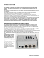
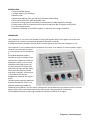
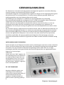
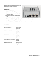
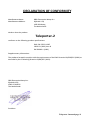
TELEPORTER 2
USER
MANUAL
VERSION 2010-001
Teleporter 2 manual page 1
Dear Customer,
Thank you for choosing the Teleporter-2.
Specialists in the field of Radio/TV Broadcast and audio production designed the Teleporter-2.
It is a system that is capable of working in a multitude of applications.
To be able to improve our products we always value suggestions once you have become familiar
with your system. We will certainly learn from your comments and very much appreciate you
dropping us a mail at [email protected]
We are confident that you will be using the Teleporter-2 for many years to come, and wish you lots
of success in your business.
And… please take some time to read this manual first to avoid unnecessary questions to yourself
and to us.
With kind regards,
Duco de Rijk
President
D&R ELECTRONICA WEESP B.V.
Rijnkade 15B
1382 GS WEESPThe Netherlands
Phone: 0294-418 014
Fax: 0294-416 987
Website: http://www.d-r.nl
E-mail: [email protected]
Teleporter 2 manual page 2
INTRODUCTION
The Teleporter 2 is the latest analog standard in portable telecommunication for professional
reporters, who require communication with their studio without any problems or hassle with
batteries.
The Teleporter is a compact reporter unit which can be used to drive domestic phone lines with Mic
and line signals.
By intelligent processing in specially designed telecommunication chips we have combined
remarkable sound quality with optimum modulation of the telephone line.
The actual use of the Teleporter-2 is very easy due to the wide dynamic range. The internal
compressor can handle any incoming signal on the Mic and or line input. A peak led indicator on
the front panel makes adjusting of incoming levels a simple task.
Besides the Mic and line input there is also a record output to record telephone conversations at
location as well as in the studio. You can use the Teleporter 2 anywhere. Advanced internal
circuitry keeps current extremely low, so batteries are not needed. The line voltage can vary
between extremes without changing any function and or transmit quality of the Teleporter 2.
RE-DIAL AND REMOTE PROGRAMMING FUNCTIONS ARE STANDARD.
The Teleporter 2 totally replaces all the functions of a modern telephone set. Functions such as
tone/mix/pulse selector, internal buzzer, re-dial functions for 23 digits, and 4 programmable
functions (A,B,C,D). The P in the dial area stands for Program, The F switch is for Flash, R for Redial, and > for PD to DTMF which is a mixed dial function.
Through the A,B,C, and D function switches it is possible to send codes to the studio to activate
further automation functions. Both Mic and line signals can be send at the same time.
The MIX control adjusts the balance between incoming and outgoing signals, and the phones control
adjusts the level. The "ON" switch connects the Teleporter 2 with the phone lines.
The "BUZZER" switch activates the internal buzzer if needed. The "RING" led indicates a call at any
time.
The back panel has metal XLR
connectors for Mic, Line and
Record in and outputs, and a
standardized telephone line
connector. The headphone
connector is on standard 1/4"
jack.
By using the Teleporter 2 you
have total control over
transmitting your valuable
interviews at any time
without the risk of running
out of batteries during long
reports.
Teleporter 2 manual page 3
SPECIFICATIES:
• Pulse and DTMF dialing.
• 23 digit capacity for re-dialing.
• Memory clear.
• Mixed mode dialing, start with PD and finish with DTMF dialing.
• Dual re-dial buffers for PBAX and public calls.
• Dynamic limiting (speech controlled) is independent of cable length/line voltage.
• Power-down input for improved performance during pulse dial or register recall (flash).
• Line loss compensation.
• Automatic disabling of the DTMF amplifier in extreme low voltage conditions.
DESCRIPTION
The Teleporter 2 is a small unit capable of mixing Mic signals and /or line signals into a two wire
telephone line, conform international telephone company standards.
A headphone output provides you with loud and clear signals to and from the Teleporter 2 unit.
The Teleporter 2 unit is powered by the telephone line, there is no battery or external power supply
necessary to make the unit work.
It is very easy to use the Teleporter
2.
A standard telephone cable is
available at your local Phone shop
connects the Teleporter 2 with the
telephone system, or an internal
telephone switching system. On
the back there are 2 female XLR
connectors for Mic and line inputs.
The male XLR output can feed a
tape deck if needed. A stereo jack
is provided for feeding the
headphones, however the signal is
mono.
The Mic input accepts any balanced
dynamic microphone. There is no
phantom powering available for
condenser microphones! The line input is designed to accept Walkman type output levels of cassette
players. Both inputs have balanced isolation transformers for ground free connections.
The headphone output accepts high impedance headsets of 600 ohm or higher.
Teleporter 2 manual page 4
CONTROL SETTINGS
On the front panel of the Teleporter 2 you notice 4 controls.
The Mic and Line knobs control the input levels of the incoming Mic and line signals. A regular flashing
LED (positioned between the two input controls) is the optimum adjustment of the level controls. In
situations where the input signal is too high and the LVL led lights continuously, an internal limiter
holds the level down to avoid distortion. Even if the signal in the headphone set distorts with too high
volume settings, the signal sent to the studio will hardly distorted.
The BAL. (balance) control reduces the level coming from the Mic line input to the headphone set.
When this control is set counter clockwise, both Mic/line signals and studio return signal are heard. By
adjusting the BAL. control the Mic/line signal will be reduced to a certain point depending upon line
impedances which may vary from situation to situation.
The BAL. control will not vary the level of the signal sent to the studio!
The PHONES control adjusts the headphone level. The record output produces the same signal as
heard on the headphone output, but it is a fixed level.
CONNECTORS
Mic in on Female XL
pin1= ground
pin2= Hot
pin3= Cold
LINE IN on female XLR
pin1= ground
pin2= Hot
pin3= Cold
RECORD OUT on male XLR
pin1= ground
pin2= Hot
pin3= Cold
Phone LINE on RJ 11connector
pin4=A
pin3=B
PHONES on stereo jack
Shield=ground
Tip= signal
Ring=signal
Teleporter 2 manual page 5
THE "ON" SWITCH.
This switch connects the Teleporter 2 to the telephone line. After hearing the dial tone you can dial
the number you want, or you can make a
connection between the Teleporter 2 and
someone who’s calling you.
The associated LED will light on incoming calls
and when you push the ON switch.
THE "BUZZER" SWITCH.
When activated the internal buzzer will buzz
during incoming calls. When you do not need
the sound of the internal buzzer when called
from your station you can switch it off. The
RING led will always indicate an incoming
call.
THE KEYBOARD
On the surface of the Teleporter 2 you will see all sorts of pushbuttons with specific functions which
will be explained in detail.
P= program switch, this switch is capable of deleting the internal redial memory as well as
programming the internal memory. Note: Only when the unit is connected to a telephone line!
The ON switch turns the Teleporter 2 on. Then hit the "P" switch, dial the number you want, hit the
"F" (flash) switch and the number is stored.
F= Flash switch, this switch disconnects the line for about 100mSec, which means that the connection
with the Telephone line is still available and that you are not losing your connection for dialing
another number. Through an internal switching system you can get an extra line with this Flash
switch. By hitting the Flash switch during an already made connection you temporarily disconnect
your connection, a new dial tone will be heard and a new connection can be made to a new
number.
By depressing the Flash switch again the "old" connection will be restored. This system will only work
with switching systems with more than one line.
R= redial. The redial function activates the last used number on the Teleporter 2. The memory will
only be available when the unit is connected to the telephone line.
Depressing this switch changes the dial function. This function is only available with the TMP switch
in its mid position. The switch changes the dial mode from pulse to tone.
TMP= This is the main switch for Pulse or Tone mode, or a mix of these two settings (M).
In T mode a tone dialing system is active. In P mode a pulse dialing system is active. In the M mode the
Teleporter 2 will automatically start functioning in the Pulse mode.
The A,B,C, en D function switches could be practical when you need to make calls to databanks.
We hope that this unit will ease your job as a reporter and look forward to hear from you if there is
any comment on this unit in field use.
Teleporter 2 manual page 6
Geachte klant,
Wij danken u hartelijk voor uw keuze en het vertrouwen dat u in ons product stelt.
U deed een goede keus, dit product is ontworpen door en voor professionele gebruikers.
Er is gebruik gemaakt van onze enorme "know how" in mengtafel en signaal processor
technieken en dit gecombineerd met hoogwaardige componenten geeft u de zekerheid van een
lange gebruiksduur.
Bovenstaande eigenschappen resulteren in een zeer betrouwbaar en Bedrijfszeker eindproduct.
Deze gebruiksaanwijzing helpt u in het optimaal benutten van alle mogelijkheden die dit product in
zich heeft.
Mocht u nog vragen hebben dan kunt u zich altijd tot onze dealers wenden en in uiterste nood
tot ons.
Duco de Rijk
Directeur
D&R ELECTRONICA WEESP B.V.
Rijnkade 15B
1382 GS WEESPThe Netherlands
Phone: 0294-418 014
Fax: 0294-416 987
Website: http://www.d-r.nl
E-mail: [email protected]
Teleporter 2 manual page 7
GEBRUIKSAANWIJZING
De Teleporter-2 is een klein en handig apparaat om laagniveau signalen te versterken afkomstig
van een microfoon en/of een band of cassette recorder.
Ook biedt de Teleporter 2 de mogelijkheid om signalen te mengen en een uitgangssignaal te geven
dat conform de PTT en omroepnormen is. Er kunnen tevens opnamen gemaakt worden van
telefoongesprekken voor latere doorzending naar de studio.
De bediening van de Teleporter 2 is ondanks zijn vele mogelijkheden zeer eenvoudig.
Een standaard telefoonkabel (te verkrijgen bij uw PTT winkel of soortgelijke zaken) verbindt uw
Teleporter2 aan het telefoonnet, dan wel met een interne huiscentrale.
Verder vindt u aan de achterzijde een female XLR connector voor de microfoon, en voor uw
lijnsignalen en een Male XLR voor verbinding met een cassettedeck voor registratie van
gesprekken. Een stereo jack verzorgt de signalen naar een stereokoptelefoon, de audio is echter
mono .
De microfoon ingang is uitgevoerd met een XLR connector. Elke ons bekende microfoon kan op
deze connector aangesloten worden. Er is slechts een uitzondering in het geval dat de microfoon
fantoomvoeding nodig heeft, er dient dan een externe fantoom voeding aangesloten te worden
alvorens het signaal op de Teleporter-2 aan te sluiten. Wij raden echter aan een dynamische
microfoon te gebruiken. De ingang is gebalanceerd uitgevoerd. De tape ingang is eveneens
uitgevoerd met een XLR connector en is geschikt voor iedere cassette recorder of walkman-achtig
player.
INSTELLINGEN VAN DE TELEPORTER-2.
Op de voorzijde van de Teleporter bevinden zich vier draaiknoppen waarmee u onder andere het
niveau van de microfoon en/of tape in kunt stellen. Een optimale instelling wordt verkregen door
het niveau zover op te draaien tot de peak led regelmatig oplicht. Indien door een te hoge
instelling de peak led continu gaat branden dan wordt het signaal door een ingebouwde limiter
begrenst om vervorming te
voorkomen.
Verder ziet u een "MIX" regelaar, die
de verhouding tussen het inkomend
en uitgaand signaal regelt wat u op
de koptelefoon hoort. Dus niet het
uitgaande niveau naar de studio!
De laatste knop "PHONES" regelt het
level in uw koptelefoon.
DE “ON” SCHAKELAAR
Met deze schakelaar maakt u een
verbinding met het telefoonnet,
waarna u een nummer kunt kiezen, of
een binnenkomende lijn kunt
oppakken. de bijbehorende led
geeft aan dat er spanning op de lijn
is.
Teleporter 2 manual page 8
DE “BUZZER" SCHAKELAAR
Ingedrukt schakelt u de interne buzzer aan. Uitgeschakeld een handige feature bij het verslaan van
bijvoorbeeld biljart wedstrijden waar het niet gewenst is dat er geluid gemaakt wordt als uw studio
u terugbelt uit kosten overwegingen. De bijbehorende led (RING) brandt altijd als de Teleporter-2
"gebeld" wordt.
HET TOETSEN VELD
Aan de bovenkant van de Teleporter-2 vindt u de druktoetsen zoals op ieder normaal
telefoontoestel. De zwarte toetsen vertegenwoordigen de bekende cijferreeks met daarbij het
"sterretje" en het "hekje" De overige grijze toetsen vertegenwoordigen de volgende functies.
P= programmeertoets, die instaat is het interne re-dial geheugen leeg te maken, dan wel het
interne geheugen te programmeren zonder een verbinding tot stand te brengen.
U zet de Teleporter-2 aan door de "ON" toets te activeren. Hierna drukt u op de "P" toets.
Type nu het gewenste nummer in, druk hierna op Flash (F) en het geheugen is geprogrammeerd.
F= de Flashtoets verbreekt de lijn slechts 100msec waardoor de verbinding met de centrale en het
mogelijk verliezen van uw netlijn voorkomen wordt. Tevens kunt u met deze toets via een centrale
een extra buitenlijn kiezen. U gaat als volgt te werk, tijdens de reeds gemaakte verbinding drukt u op
de Flash toets waarna de verbinding schijnbaar verbroken is, en een nieuwe netlijn zich aandient.
Door nogmaals op de Flash toets te drukken krijgt u uw "oude" verbinding weer terug. Dit kan
echter alleen bij interne centrales met meerdere lijnen.
R= re-dial. Deze toets herhaalt het laatst gekozen nummer. LET OP, het geheugen wordt
leeggemaakt door o.a. het afkoppelen van de Teleporter-2 van het telefoonnet. Dit komt doordat
de Teleporter2 (gelukkig) geen interne batterijen heeft.
>= Het veranderen van de kies funktie. Deze functie is alleen bruikbaar in de middenstand van de TMP
schakelaar linksboven op uw Teleporter-2. Deze toets wijzigt de kiesprocedure van "Puls" naar
Tone .
TMP= de hoofdkeuze schakelaar voor Puls, Tone, en een gemixte situatie (M). Indien u de M
gekozen heeft start de Teleporter-2 automatisch op in de Puls mode.
De A,B,C, en D functietoetsen zijn nodig bij het bellen naar computer databanken . DE
IN/UITGANGEN
Een speciale transformator in de Teleporter-2 zorgt voor een perfecte symmetrische aardvrij telefoon
aanpassing aan de telefoonlijn. De Teleporter-2 uitgang voldoet aan de gestelde PTT en
omroepnormen.
Linksop de achterkant van de Teleporter-2 bevindt zich de head phone uitgang. Deze uitgang is geschikt
om een hoogohmige koptelefoon aan te sluiten, waardoor het mogelijk is om het weggestuurde en
inkomende signalen te beluisteren.
D&R Electronica Weesp b.v. rijnkade 15B, 1382GS WEESP Tel: 0294-418014, Fax: 0294-416987
Teleporter 2 manual page 9
Wij hopen dat u veel plezier en praktisch nut zult
beleven aan de nieuwe Teleporter-2
SPECIFICATIES:
• Pulse and DTMF dialing.
• 23 digit capacity for re-dialing.
• Memory clear.
• Mixed mode dialing, start with PD and finish
with DTMF dialing.
• Dual re-dial buffers for PBAX and public
calls.
• Dynamic limiting (speech controlled) is
independent of cable length/line voltage. Power-down input for improved performance
during pulse dial or register recall (flash).
• Line loss compensation.
• Automatic disabling of the DTMF amplifier in extreme low voltage conditions.
CONNECTORS
Mic in on Female XL
pin1= ground
pin2= Hot
pin3= Cold
LINE IN on female XLR
pin1= ground
pin2= Hot
pin3= Cold
RECORD OUT on male XLR
pin1= ground
pin2= Hot
pin3= Cold
Phone LINE on RJ 11connector
pin4=A
pin3=B
PHONES on stereo jack
Shield=ground
Tip= signal
Ring=signal
Teleporter 2 manual page 10
DECLARATION OF CONFORMITY
Manufacturers Name:
Manufacturers Address:
D&R Electronica Weesp b.v.
Rijnkade 1 5B,
1382 GS Weesp,
The Netherlands
declares that the product
Teleporter-2
conforms to the following product specifications:
EMC: EN 55022: 1987
CISPR 22 (1993) class B
EN 500082-1 (1992)
Supplementary Information:
The products herewith complies with the requirements of the EMC Directive 89/336/EEC (1989) as
amended by the CE Marking Directive 93/68/EEC (1993).
D&R Electronica Weesp b.v.
Rijnkade 15 B
1382 GS WEESP
The Netherlands
President
Teleporter 2 manual page 11
PRODUCT SAFETY
This product is manufactured with the highest standards and is double checked in our quality control
department for reliability in the "HIGH VOLTAGE" section.
CAUTION
Never remove any panels, or open this equipment. No user serviceable parts inside. Equipment power
supply must be grounded at all times. Only use this product as described, in user manual or
brochure. Do not operate this equipment in high humidity or expose it to water or other liquids.
Check the AC power supply cable to assure secure contact. Have your equipment checked yearly
by a qualified dealer service center. Hazardous electrical shock can be avoided by carefully
following the above rules.
EXTRA CAUTION FOR LIVE SOUND
Ground all equipment using the ground pin in the AC power supply cable.
Never remove this pin. Ground loops should be eliminated only by use of isolation transformers for
all inputs and outputs. Replace any blown fuse with the same type and rating only after
equipment has been disconnected from AC power. If problem persists, return equipment to
qualified service technician
PLEASE READ THE FOLLOWING INFORMATION
Especially in sound equipment on stage the following information is essential to know.
An electrical shock is caused by voltage and current, actually it is the current that causes the shock.
In practice the higher the voltage the higher the current will be and the higher the shock.
But there is another thing to consider and it is resistance. When the resistance in Ohms is high
between two poles, the current will be low and vice versa. All three of these; voltage, current. and
resistance are important in determining the effect of an electrical shock.
However, the severity of a shock primarily determined by the amount of current flowing through a
person.
A person can feel a shock because the muscles in a body respond to electrical current and because
the heart is a muscle it can affect, when the current is high enough.
Current can also be fatal when it causes the chest muscles to contract and stop breathing. At what
potential is current dangerous. Well the first feeling of current is a tingle at 0.00 1 Amp of current.
The current between 0.1 Amp and 0.2 Amp is fatal. Imagine that your home fuses of 20 Amp can
handle 200 times more current than is necessary to kill. How does resistance affect the shock a
person feels. A typical resistance between one hand to the other in "dry" condition could well over
100,000 Ohm. And last but not least be careful not to touch a person being shocked as you, yourself
could also be shocked. Once removed from the shock, have someone send for medical help
immediately.
Always keep the above mentioned information in mind when using electrically powered equipment.
D&R ELECTRONICA WEESP B.V.
Rijnkade 15 11, 1382 GS WEESP
The Netherlands
Phone +31 294-418014
Fax: +31 294-416987
Email: [email protected]
Website: www.d-r.nl
Teleporter 2 manual page 12