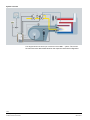
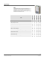
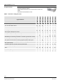
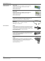
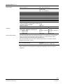
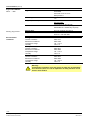
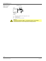
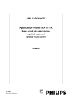
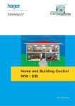
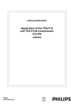
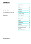
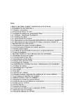
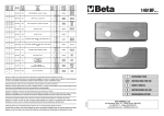
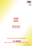
1
7 Burner controls 105 LME7... The burner control LME7... is a microprocessor-based unit with matching system components for the control and supervision of forced draft burners of medium to high capacity. The LME7… and this Data Sheet are intended for use by OEMs which integrate the LME7... in their products. Use LME7… are used for the startup and supervision of multistage or modulating forced draft burners and atmospheric gas burners in intermittent operation The fuel-air ratio can be set either via an air damper actuator - acting on mechanical or pneumatic ratio control - or via pulse width modulated fans and pneumatic ratio control. The flame supervision supervised with ionization probe and with UV flame detector QRA2..., QRA4.U or QRA10.... Gas burner controls to EN 298: 2003 Oil burner controls to EN 230: 2005 For gas forced draft burners to EN 676 For oil burners with fan to EN 267 Notes Caution! All safety, warning and technical notes given in the Basic Documentation of the LME7… (P7105) also apply to this document! If not observed, there is a risk that safety functions will be impaired and that a risk of electric shock will exist! CC1N7105en 08.12.2011 Building Technologies Division Infrastructure & Cities Sector Features - Undervoltage detection Electrical remote reset facility Accurate control times thanks to digital signal handling Multicolor indication of fault status and operating state messages Air pressure supervision with function check of air pressure switch during start and operation Repetition limitation Controlled intermittent operation after 24 hours of continuous operation (can be parameterized via parameter 239) depending on program module PME... BCI Unit parameter adjustable either via display or PC software ACS410 Connection for program module PME... Only LME71.../LME73...: Indication of program sequence - Integrated in the basic unit LME7... are: Burner control BCI for connection a display or PC Lockout reset button (info button) 3 multi color signal lamp LED for operations and fault notifications Optional: Analog inputs for load controller DC 0...10 V, DC 0/4...20 mA, 0...135 Ω Interface for program module Only LME71.../LME73...: Optional: 3 x 7 segment display for fault and state information's and parameter display Control for one actuator Supplementary documentation User Documentation LME73.000.../PME73.840... .................................................. A7105 Environmental Product Declaration LME… ............................................................ E7105 Environmental Product Declaration PME… ......................................................... E7105.1 Basic Documentation LME7… ................................................................................ P7105 Product Overview LME…........................................................................................Q7101 2/29 Building Technologies Division Infrastructure & Cities Sector CC1N7105en 08.12.2011 Standards and certificates Conformity to EEC directives - Electromagnetic compatibility EMC (immunity) - Directives for gas-fired appliances - Low-voltage directive ISO 9001: 2010 Zert. 00739 2004/108/EC 2009/142/EC 2006/95/EC ISO 14001: 2010 Zert. 38233 Only AC 120 V versions Identification code to EN 298 chapter 4 PME71.401..: F M C L J N PME71.402...:F B C L J N PME71.901...: F M C L G N PME72.521..: F M L L X N PME72.541..: F B L L X N PME73.810..: F M C L J N PME73.820..: F M C L J N PME73.830..: F B C L J N PME73.831..: F B L L J N PME73.840..: F B C L J N Life cycle Burner controls LME7… has a designed lifetime* of 250,000 burner startup cycles which, under normal operating conditions in heating mode, correspond to approx. 10 years of usage (starting from the production date given on the type field). This lifetime is based on the endurance tests specified in standard EN 230/EN 298 and the table containing the relevant test documentation as published by the European Association of Component Manufacturers (Afecor) (www.afecor.org). The designed lifetime is based on use of the burner controls according to the manufacturer’s Data Sheet and Basic Documentation. After reaching the designed lifetime in terms of the number of burner startup cycles, or the respective time of usage, the burner control is to be replaced by authorized personnel. * The designed lifetime is not the warranty time specified in the Terms of Delivery 3/29 Building Technologies Division Infrastructure & Cities Sector CC1N7105en 08.12.2011 System overview The diagram shows the full scope of functions of the LME7… system. The correct functions are to be determined based on the respective execution/configuration. 4/29 Building Technologies Division Infrastructure & Cities Sector CC1N7105en 08.12.2011 Type summary Burner control --- --- ● --- Mains voltage AC 230 V --- Load controller input 3-position step input/2-stage ● ● ● ● ● ● ● ● ● ● ● ● ● --- Gas pressure switch-min/POC ● ● ● ● ● ● ● ● Output actuator control --- --- ● ● Input feedback for actuator with potentiometer 0...1 k --- --- --- Output PWM control ● ● ● ● ● ● ● ● ● ● ● ● ● ● ● ● ● ● ● ● Air pressure switch Ionization probe QRA2.../QRA4.U/QRA10... Load controller analog input signal (0...10 V, 4...20 mA, 0...135 ) Onboard LED 7-segment display BCI bus for AZL2... --- --- ● ● ● ● ● ● ● ● ● ● ● ● ● LME73.000A2 LME72.000A2 ● Pressure switch valve proving LME73.000A1 LME71.000A2 Mains voltage AC 120 V Type LME71.000A1 LME7... Parameterized burner control for the supervision of multistage or modulating oil/gas forced draft burners and atmospheric burners of medium to higher capacity, in intermittent operation. With controlled air damper control. See Basic Documentation P7105 5/29 Building Technologies Division Infrastructure & Cities Sector CC1N7105en 08.12.2011 Type summary (cont'd) PME7... Program module for LME7... With program sequences oil or gas burners for basic unit LME7... See Basic Documentation P7105 Program module PME73.840A1 PME73.831A1 PME73.830A1 PME73.820A1 PME73.810A1 PME71.901A1 PME71.402A1 Type reference PME71.401A1 PME7... with mains voltage AC 120 V ● ● ● ● ● ● ● ● ● For use with LME71.000A... ● ● --- --- --- --- --- For use with LME72.000A... --- --- --- --- --- --- --- --- For use with LME73.000A... --- --- --- Gas program forced draft burner ● ● ● ● ● ● ● ● ● ● ● ● ● Gas program atmospheric burner --- --- --- --- --- --- --- --- 1-stage/2-stage or 1-stage modulating ● ● ● --- ● ● ● Pilot burner simultaneously/alternately --- --- --- Modulating via actuator (pneumatic or mechanic gas-air ratio control) --- --- --- ● ● ● ● ● ● ● ● ● ● ● Modulating via PWM fan (pneumatic or mechanic gas-air ratio control) --- --- --- --- --- --- --- Fan speed control/control via analog signal/3-position step signal --- --- ● ● --- --- --- --- --- Actuator control via analog signal/3-position step signal for actuator with potentiometer --- --- --- ● --- ● ● --- 3-position signal for actuator without potentiometer --- --- --- --- --- Control sequence programmable time POC ● ● ● ● Valve proving --- --- Input valve proving ON/Off --- --- ● ● ● --- ● ● ● --- ● ● ● ● --- ● ● --● ● ● ● ● ● --- Mains voltage AC 120 V ● ● ● --- 6/29 Building Technologies Division Infrastructure & Cities Sector CC1N7105en 08.12.2011 Type summary (cont'd) PME73.840A2 PME73.831A2 PME73.830A2 PME73.820A2 PME73.810A2 PME72.541A2 PME72.521A2 PME71.901A2 PME71.402A2 Type reference PME71.401A2 PME7... with mains voltage AC 230 V ● ● ● ● ● ● ● ● ● ● ● For use with LME71.000A... ● ● --- --- --- --- --- --- --- For use with LME72.000A... --- --- --- ● ● --- --- --- --- --- For use with LME73.000A... --- --- --- --- --- Gas program forced draft burner ● ● ● ● ● ● ● ● ● ● ● ● ● ● ● Gas program atmospheric burner --- --- --- --- --- --- --- --- --- --- 1-stage/2-stage or 1-stage modulating ● ● ● ● --- --- --- --- --- Modulating via actuator (pneumatic or mechanic gas-air ratio control) --- --- --- ● ● ● ● ● Pilot burner simultaneously/alternately ● ● ● ● ● ● ● ● ● ● ● ● ● Modulating via PWM fan (pneumatic or mechanic gas-air ratio control) --- --- ● --- --- --- --- --- --- --- Fan speed control/control via analog signal/3-position step signal --- --- ● --- --- --- --- --- --- --- Actuator control via analog signal/3-position step signal for actuator with potentiometer --- --- --- --- --- ● --- ● ● --- 3-position signal for actuator without potentiometer --- --- --- ● ● --- --- Control sequence programmable time ● ● --- --- ● ● Valve proving --- --- ● ● ● --- --- ● ● ● ● ● POC ● ● ● ● ● ● ● ● ● ● Input valve proving ON/Off --- --- --- --- --- --- --- --- Mains voltage AC 230 V ● ● ● --- ● ● --- 7/29 Building Technologies Division Infrastructure & Cities Sector CC1N7105en 08.12.2011 Type summary (cont´d) Display/operating units and accessories AZL21.00A9 Display and operating unit, detached, choice of mounting methods with LCD, 8-digit, 5 buttons, BCI for LME7..., degree of protection IP40. See Data Sheet N7542 AZL23.00A9 Display and operating unit, detached, choice of mounting methods with LCD, 8-digit, 5 buttons, BCI for LME7..., degree of protection IP54. See Data Sheet N7542 Built-in in the LME7... 3-colored LED, reset button (info button), 3 other buttons for operation in connection with 3 x 7-segment display AGV50.100 Signal cable for AZL2..., with RJ11 connector, cable length 1 m, pack of 10 Flame detectors QRA2… UV flame detector for the supervision of gas flames and yellow/blue-burning oil flames and for ignition spark proving. Plastic insulated housing, metalized to prevent static charging caused by the air flow from the fan, lateral illumination. See Data Sheet N7712 QRA4.U UV flame detector for the supervision of gas flames and yellow/blue-burning oil flames and for ignition spark proving, metal housing, and frontal illumination. See Data Sheet N7711 QRA10… UV flame detector for supervision of gas flames and yellow/blue-burning oil flames and for ignition spark proving. Die-cast aluminium housing with a 1 in. mounting coupling and connection facility for cooling air. See Data Sheet N7712 8/29 Building Technologies Division Infrastructure & Cities Sector CC1N7105en 08.12.2011 Type summary (cont´d) Actuators SQN3… Electromotoric actuators for use with air dampers and control valves of oil or gas burners of small to medium capacity. Holding torque/running time 0,8 Nm/4,5 s up to 3 Nm/30 s See Data Sheet N7808 SQN7… Electromotoric actuators for air dampers and control valves of oil and gas burners of small to medium capacity. Holding torque/running time 0,7 Nm/4 s up to 2,5 Nm/30 s See Data Sheet N7804 SQM40…/SQM41... Electromotoric actuators for air dampers and control valves of oil and gas burners of medium to high capacity, with ULregistered. Holding torque / running time 5 Nm/15 s up to 10 Nm/30 s See Data Sheet N7817 SQM5... Electromotoric actuators for air dampers and control valves of oil and gas burners of medium to high capacity, with ULregistered. Holding torque/running time 10 Nm/15 s up to 40 Nm/60 s See Data Sheet N7815 Pressure switch Dummy plug for RJ11 QPLx5… The pressure switch is used for monitoring of gas or air pressure. See Data Sheet N7221 Dummy plug For 6-pole modulating connector (RJ11) Supplier recommendation: Molex, order number: 085 999 3256 9/29 Building Technologies Division Infrastructure & Cities Sector CC1N7105en 08.12.2011 Type summary (cont´d) Connector set for LME7... AGG3.710 Connector set complete RAST5 and RAST3.5 Single packs See object list C7105 (74 319 0642 0) Example: X5-03 AGG3.720 10 standard connector set complete RAST5 and RAST3.5 Packing in bags of 10 pieces each connector type. See object list C7105 (74 319 0642 0) AGG3.730 50 standard connector set complete RAST5 and RAST3.5 Packing in bags of 50 pieces each connector type. See object list C7105 (74 319 0642 0) Service tools OCI410… Interface between burner control and PC Facilitates viewing, handling and recording setting parameters on site in connection with the PC software ACS410. See Data Sheet N7616 ACS410 PC software for setting the parameters and for visualizing the burner controls. See Software Documentation J7352 Test case and accessories KF8895.1A9 Test case for LME... For simulations of burner functions as startups, sequences of operations in connection with the specified burner controls For check and test purposes of burner controls For operation in laboratories by expert qualified personnel See User Manual U7993 AGV8895.01 Connection cable set for LME7… For test case KF8895.1A9 Consisting of: AGV8895.01X1 Connection cable for mains potential For test case KF8895.1A9 AGV8895.01X3 Connection cable for extra-low voltage, PELV For test case KF8895.1A9 10/29 Building Technologies Division Infrastructure & Cities Sector CC1N7105en 08.12.2011 Technical data Basic unit LME7... General Mains voltage Mains frequency External primary fuse Power consumption Safety class Degree of protection AC 120 V AC 230 V 50/60 Hz 50/60 Hz Max. 6.3 A (slow) Max. 6.3 A (slow) <10 W, typical <10 W, typical I with parts according to II and III to DIN EN 60730-1 IP00 Perm. mounting position Weight Terminal rating Inputs Note: The burner or boiler manufacturer must ensure degree of protection IP40 for burner controls as per DIN EN 60529 through adequate installation of the LME7... Optional Approx. 490 g Mains voltage: Input current depending on the operating state of the unit Under voltage UMains 120 V UMains 230 V Safety shutdown from the operating ≤AC 75 V ≤AC 165 V position takes place should mains voltage drop Restart is initiated when mains ≥AC 100 V ≥AC 195 V voltage exceeds State inputs, temperature controller, temperature switch, load controller, pressure switch, air pressure switch, actuator (except safety loop) of the contact feedback network are used for system supervision and require mains-related input voltage Input safety loop See Terminal rating outputs Input currents and input voltages - UeMax UN +10% UN +10% - UeMin UN -15% UN -15% - IeMax 1.5 mA peak 1 mA peak (peak value) (peak value) - IeMin 0.8 mA peak 0.5 mA peak (peak value) (peak value) Gold-plated silver contacts Contact material recommended for external signal sources (air pressure switch, pressure switch-min, pressure switch-max, etc.) Transition/settling behavior/bounce - Perm. bounce time of contacts when switching ON/OFF Max. 50 ms (after the bounce time, the contact must stay closed or open) UN AC 120 V AC 230 V Voltage detection - ON >AC 60 V >AC 120 V - OFF <AC 40 V <AC 80 V Analog input X65 DC 0...10 V/DC 0/4...20 mA/0...135 Ω 11/29 Building Technologies Division Infrastructure & Cities Sector CC1N7105en 08.12.2011 Technical data (cont´d) Terminal rating Outputs Total contact loading: Rated voltage Unit input current X3-04 (safety loop) from: - Fan motor contactor - Ignition transformer - Fuel valves Individual contact loading: Fan motor contactor X2-01 pin 3 Rated voltage Rated current AC 120 V 50/60 Hz Max. 5 A AC 230 V 50/60 Hz Max. 5 A AC 120 V 50/60 Hz 2A (15A max. 0.5 s) Cos 0.4 AC 230 V 50/60 Hz 2A (15A for max. 0.5s) Cos 0.4 Power factor Alarm output X2-03 pin 3 Rated voltage AC 120 V 50/60 Hz AC 230 V 50/60 Hz Rated current 1A 1A Power factor Cos >0.6 Cos >0.6 Ignition transformer X4-02 pin 3 Rated voltage AC 120 V 50/60 Hz AC 230 V 50/60 Hz Rated current 2A 2A Power factor Cos >0.4 Cos >0.4 Auxiliary output Rated voltage AC 120 V 50/60 Hz AC 230 V 50/60 Hz Rated current 1A 1A Power factor Cos >0,6 Cos >0,6 Output relay contact K2 X2-09 pin 7 Rated voltage AC 120 V 50/60 Hz AC 230 V 50/60 Hz Rated current 1A 1A Power factor Cos >0.4 Cos >0.4 Fuel valves/pilot valve X7-01 pin 3 Rated voltage AC 120 V 50/60 Hz AC 230 V 50/60 Hz Rated current 1A 1A Power factor Cos >0.4 Cos >0.4 Fuel valves 1 X7-04 pin 4/ fuel valve 2 X7-02 pin 3 Rated voltage AC 120 V 50/60 Hz AC 230 V 50/60 Hz Rated current 2A 2A - Valve proving inactive - Valve proving active 1A 1A Power factor Cos >0.4 Cos >0.4 Note: When activating valve proving (e.g. on shutdown), the load on the valve terminals is restricted. If the load is not reduced, the design lifetime is about 100,000 burner start cycles! Safety valve X6-03 pin 3 Rated voltage AC 120 V 50/60 Hz AC 230 V 50/60 Hz Total current 1.5 A 1.5 A Power factor Cos >0.6 Cos >0.6 Safety loop X3-04 pin 2, safety valve X6-03 pin 3, POC X2-02 pin 3 Rated voltage AC 120 V 50/60 Hz AC 230 V 50/60 Hz Total current 2A 2A Power factor Cos >0.4 Cos >0.4 12/29 Building Technologies Division Infrastructure & Cities Sector CC1N7105en 08.12.2011 Technical data (cont´d) Cable lengths Mains supply line Display, BCI Load controller X5-03 Safety Loop Safety valve Fuel valve Ignition transformer Remote reset (lay separate cable) Other lines Max. 100 m (100 pF/m) For use under the burner hood or in a control panel Max. 1 m (100 pF/m) Max. 30 m (100 pF/m) Max. 30 m (100 pF/m) Max. 30 m (100 pF/m) Max. 30 m (100 pF/m) Max. 30 m (100 pF/m) Max. 30 m (100 pF/m) Max. 30 m (100 pF/m) Specification as per EN 60730-1 Type of shutdown or interruption of each circuit Shutdown with microswitch 1 pole Actuators Cross-sectional areas Mode of operation Type 2 B CLOSE/ignition position/OPEN X2-09 pin 1, X2-09 pin 2, X2-09 pin 3 Rated voltage Rated current Power factor 1 mio. switching cycles AC 120 V 50/60 Hz 0,1 A Cos >0.6 1 mio. switching cycles AC 230 V 50/60 Hz 0,1 A Cos >0.6 The cross-sectional areas of the mains power lines (L, N, and PE) and, if required, the safety loop (safety limit thermostat, water shortage, etc.) must be sized for rated currents according to the selected external primary fuse. The cross-sectional areas of the other cables must be sized in accordance with the internal unit fuse (max. 6.3 AT). Min. cross-sectional area 0.75 mm² (single- or multicore to VDE 0100) Cable insulation must be suited for the respective temperature and environmental conditions! 13/29 Building Technologies Division Infrastructure & Cities Sector CC1N7105en 08.12.2011 Technical Data (cont´d) Signal cable AGV50... AZL2... BCI Signal cable Color white Unshielded Conductor 4 x 0.141 mm² With jack RJ11 Cable length AGV50.100 Supplier (alternative) Location 1m Recommendation: Hütter http://www.hktnetzwerktechnik.at/index.htm Under the burner hood (arrangements for SKII EN60730-1 additionally required) Dummy plug for RJ11 Dummy plug Supplier For 6 pin modular plug (RJ11) Recommendation: Molex Order no.: 085 999 3256 Environmental conditions Storage Climatic conditions Mechanical conditions Temperature range Humidity Transport Climatic conditions Mechanical conditions Temperature range Humidity Operation Climatic conditions Mechanical conditions Temperature range Humidity DIN EN 60721-3-1 Class 1K3 Class 1M2 -40...+70 °C <95% r.h. DIN EN 60721-3-2 Class 2K3 Class 2M2 -40...+70 °C <95% r.h. DIN EN 60721-3-3 Class 3K3 Class 3M2 -40...+60 °C <95% r.h. Warning! Condensation, formation of ice and ingress of water are not permitted! If not observed, there is a risk of impairment of safety functions and of electric shock hazard. 14/29 Building Technologies Division Infrastructure & Cities Sector CC1N7105en 08.12.2011 Technical Data (cont´d) Flame supervision with ionization probe No-load voltage at terminal ionization probe (X10–05 pin 2) AC 300 V Warning! The ionization probe must be protected against electric shock hazard! When monitoring ionization currents in earth-free mains, connect terminal X10-05 pin 1 to burner ground Short-circuit current Required detector current Possible detector current Permissible length of detector cable (laid separately) Max. AC 1 mA Min. DC 1 µA, display approx. 20% Max. DC 40 µA, display approx. 100% 30 m (core-earth 100 pF/m) Note: As the detector line capacitance (line length) increases, the voltage at the ionization probe und thus the detector current will drop. Extremely long line lengths and very high-ohmic flames might necessitate the use of low-capacitance cable (e.g. ignition cable). In spite of special electronic circuits designed to compensate possible adverse effects of the ignition spark on the ionization current, it must be made certain that the minimum detector current required is already available during the ignition phase. If this is not the case, the primary ignition transformer connections must be interchanged and/or the electrodes relocated. Threshold values when flame is supervised by ionization - Start prevention (extraneous light) - Intensity (parameter 954) approx. 12% - Operation - Intensity (parameter 954) approx. 13% ION input 100 90 Flame intensity in % 80 70 60 50 40 30 20 10 0 Ionization current in µA 15/29 Building Technologies Division Infrastructure & Cities Sector CC1N7105en 08.12.2011 Technical Data (cont´d) Measuring circuit for detector current measurement Ionization probe LME7... X10-05/2 M C ION X10-05/1 Legend C ION M Electrolytic condenser 100...470 µF; DC 10...25 V Ionization probe Microammeter Ri max. 5,000 Warning! Simultaneous operation of QRA... and ionization probe is not permitted! If not observed, there is a risk of impairment of safety functions. 16/29 Building Technologies Division Infrastructure & Cities Sector CC1N7105en 08.12.2011 Technical Data (cont´d) Flame supervision with QRA2... / QRA4.U / QRA10... Caution! If flame detectors QRA2…/QRA4.U/QRA10... are used for flame supervision with the LME7..., it must be ensured that the burner control is permanently connected to power (conforming to EN 298), thus enabling the system to detect flame detector failures during startup and shutdown. Generally, the system works with flame detectors QRA... in intermittent operation. If this is not observed, there is a risk of loss of safety functions. Technical Data see Data Sheet N7712, flame detector QRA2.../QRA10…! Technical Data see Data Sheet N7711, flame detector QRA4.U! Threshold values when flame is supervised by QRA... - Start prevention (extraneous light) - Intensity (parameter 954) approx. 12% - Operation - Intensity (parameter 954) approx. 13% Operating voltage Mains frequency Required detector current in operation Possible detector current in operation AC 280 V ±15% 50...60 Hz 6% Min. 70 µA Max. 700 µA Perm. length of detector cable (normal cable, laid separately) ¹) Max. 100 m ¹) Multicore cable not permitted Flame detector QRA... Measuring circuit for detector current measurement QRA... Legend A C M Exposure to light Electrolytic condenser 100...470 µF; DC 10...25 V Microammeter Ri max. 5,000 Warning! Input QRA... is not short-circuit-proof! Short-circuits of X10-06 pin 2 against earth can destroy the QRA... input Simultaneous operation of flame detector QRA... and ionization probe is not permitted. If not observed, there is a risk of impairment of safety functions. To make certain the age of the UV tube can be determined, the LME7... basic unit must always be connected to mains supply. If not observed, there is a risk of impairment of safety functions. 17/29 Building Technologies Division Infrastructure & Cities Sector CC1N7105en 08.12.2011 Connection diagram LME71... for PME71.401... 18/29 Building Technologies Division Infrastructure & Cities Sector CC1N7105en 08.12.2011 Connection diagram LME71... for PME71.402... 19/29 Building Technologies Division Infrastructure & Cities Sector CC1N7105en 08.12.2011 Connection diagram LME71... for PME71.901... 20/29 Building Technologies Division Infrastructure & Cities Sector CC1N7105en 08.12.2011 Connection diagram LME72... for PME72.521... 21/29 Building Technologies Division Infrastructure & Cities Sector CC1N7105en 08.12.2011 Connection diagram LME72... for PME72.541... 22/29 Building Technologies Division Infrastructure & Cities Sector CC1N7105en 08.12.2011 Connection diagram LME73... for PME73.810... 23/29 Building Technologies Division Infrastructure & Cities Sector CC1N7105en 08.12.2011 Connection diagram LME73... for PME73.820... 24/29 Building Technologies Division Infrastructure & Cities Sector CC1N7105en 08.12.2011 Connection diagram LME73... for PME73.830... 25/29 Building Technologies Division Infrastructure & Cities Sector CC1N7105en 08.12.2011 Connection diagram LME73... for PME73.831... 26/29 Building Technologies Division Infrastructure & Cities Sector CC1N7105en 08.12.2011 Connection diagram LME73... for PME73.840... 27/29 Building Technologies Division Infrastructure & Cities Sector CC1N7105en 08.12.2011 Legend AL AUX Dbr Alarm device Auxiliary output Wire link Lockout reset button (info button) /reset (EK1) EK2 FSV ION K... LED LP LR LR-OPEN LR-CLOSE M NT P LT Pmax Pmin POC PV QRA... R SA SA-KL SA-NL SA-R SA-Z SA-ZL SL STB SV V1 V2 V2a W Z Remote lockout reset button Flame signal amplifier Ionization probe Relay contact 3-color signal lamp Air pressure switch Load controller Load controller OPEN position Load controller CLOSE position Fan motor Power supply unit Pressure switch valve proving Pressure switch-max Pressure switch-min Proof of closure Pilot valve Flame detector Control thermostat or pressurestat Actuator Actuator low-fire Actuator high-fire Actuator feedback Actuator CLOSE Actuator ignition load Safety loop Safety limit thermostat Safety valve Fuel valve Fuel valve Fuel valve Limit thermostat or pressure switch Ignition transformer µC µC controller Input/output signal 1 (ON) Input/output signal 2 (OFF) Input permissible signal 1 (ON) or 0 (OFF) 28/29 Building Technologies Division Infrastructure & Cities Sector CC1N7105en 08.12.2011 Dimensions Dimensions in mm LME7… 7105m02/0510 A - + nfo 2011 Siemens AG Infrastructure & Cities Sector Building Technologies Division Subject to change! Building Technologies Division Infrastructure & Cities Sector 29/29 CC1N7105en 08.12.2011