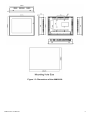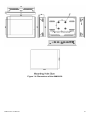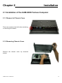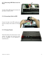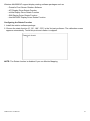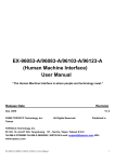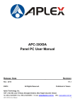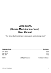
1
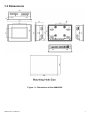
AHM-6xx8 (Human Machine Interface) User Manual “The Human Machine Interface is where people and technology meet.” Release Date Revision Sep 2009 Oct 2012 ®2012 Aplex Technology, Inc. V1.0 V1.1 All Rights Reserved. Published in Taiwan Aplex Technology, Inc. 15F-1, No.186, Jian Yi Road, Zhonghe District, New Taipei City 235, Taiwan Tel: 886-2-82262881 Fax: 886-2-82262883 E-mail: [email protected] URL: www.aplex.com.tw AHM-6xx8 User Manual 1 Warning!___________________________________ This equipment generates, uses and can radiate radio frequency energy and if not installed and used in accordance with the instructions manual, it may cause interference to radio communications. It has been tested and found to comply with the limits for a Class A computing device pursuant to FCC Rules, which are designed to provide reasonable protection against such interference when operated in a commercial environment. Operation of this equipment in a residential area is likely to cause interference in which case the user at his own expense will be required to take whatever measures may be required to correct the interference. Electric Shock Hazard – Do not operate the workstation with its back cover removed. There are dangerous high voltages inside. Disclaimer This information in this document is subject to change without notice. In no event shall Aplex Technology Inc. be liable for damages of any kind, whether incidental or consequential, arising from either the use or misuse of information in this document or in any related materials. AHM-6xx8 User Manual 2 Table of Contents______________________ Warning!…………………………………………………………………………….……..….2 Disclaimer………………………………………………………………….…………………2 Chapter 1 1.1 1.2 1.3 1.4 Chapter 2 Getting Started Features…………………………………………….……………………..5 Specifications……………………………...………………………….......5 Dimension.....……..........…………….…………………………….…..7 Brief Description…………………………………………………….……11 Hardware 2.1 Installing HDD …….……………………...………………………….....12 2.2 Panel Mounting and VESA Mounting………………………………..14 2.3 Component Locations…………………………………………………..15 2.4 Jumpers Setting & Connectors…………………………………………..16 Chapter 3 BIOS Setup 3.1 System Test and initialization...........................................................24 3.2 Award BIOS Setup ............................................................................24 Chapter 4 4.1 4.2 4.3 4.4 Chapter 5 Installation of Drivers Intel Chipset Driver.…………………………...…………………………27 Intel Graphics Media Accelerator Driver...………………………..31 Intel LAN Device…………….…………………….………………….34 Realtek Audio Driver Installation…….…………..…………………37 Touch Screen Installation 5.1 Introduction to Controller Board..…………………………..……………40 5.2 Windows XP/2003/Vista Universal Driver Installation………..….40 AHM-6xx8 User Manual 3 Figures Figure Figure Figure Figure Figure Figure Figure Figure Figure AHM-6xx8 User Manual 1.1: 1.2: 1.3: 1.4: 1.5: 1.6: 2.1: 2.2: 5.1 AHM-6058 Dimensions……………………………………..…....7 AHM-6088 Dimensions…………………………………………..8 AHM-6108 Dimensions………….……………………………….9 AHM-6128 Dimensions………..……………………………….10 Front View ……………………………………………………….11 Rear View………………………………………………………...11 Panel Mounting…………………………………………………..14 VESA Mounting…………………………………………………..14 Birdeye’s View of Control Board……………………………41 4 Chapter 1 Getting Started 1.1 Features Fanless Design Intel® Atom™ Z510 1.1GHz CPU built-in, upgrade to Z530 1.6GHz CPU 5.7”/8”/10.4”/12.1”High Brightness TFT LCD with Resolution of 640x480/800x600 NEMA 4/ IP 65 Compliant front Panel Sealed Resistive Touch Screen 1GB DDR2 400MHz DRAM DC 9~32V Wide Range Power Input 1.2 Specifications Model AHM-6058 AHM-6088 AHM-6108 AHM-6128 System ® ™ Processor Intel Atom Z510 1.1GHz CPU Default, upgrade to Z530 1.6GHz CPU System Memory 1GB DDR2 400MHz DRAM System Chipset Intel® US15W External I/O Port 2 x USB 2.0 ports 2 x RJ-45 LAN ports 1 x RS232 (COM1) 1 x RS232/422/485 (COM2),, default RS-232 1 x Line-out 1 x DC power input Storage 1 x 2.5” HDD 1 x internal CF slot ® OS Support Windows CE 5.0, CE 6.0, XP Pro, XP Embedded LCD AHM-6058 AHM-6088 AHM-6108 AHM-6128 Display Type 5.7” TFT-LCD 8” TFT-LCD 10.4” TFT-LCD 12.1” TFT-LCD Max. Resolution 640x480 800x600 800x600 800x600 Max. Color 262K 262K 262K 262K Luminance 400 400 250 350 H:140° / V:100° H:130° / V:120° H:130° / V:110° H:140° / V:110° 2 (cd/m ) View Angle AHM-6xx8 User Manual 5 Backlight 40,000hrs, LED 40,000hrs, LED Lifetime Backlight Backlight 20,000hrs, CCFL 50,000hrs, LED Backlight Touch Screen Type Analog resistive Light 80% Transmission Power Supply Power Input DC 9~32V Mechanical AHM-6058 AHM-6088 Construction Plastic molding front Plastic molding front panel and plastic housing / Plastic molding front panel and metal Black panel and metal AHM-6108 housing / Black AHM-6128 housing / Black IP Rating Front Panel IP65 Mounting Panel / VESA 75x75 Mount Dimension 204(W)x149(H)x65(D) 231(W)x176(H)x57(D) 271(W)x213(H)x57(D) 317(W)x243(H)x58(D) Environmental Operating 0~50 ゚ C Temperature Storage -20~60 ゚ C Temperature Storage Humidity 10~90% @40℃, non-condensing Certificate Meet CE/FCC Class A AHM-6xx8 User Manual 6 1.3 Dimensions Figure 1.1: Dimensions of the AHM-6058 AHM-6xx8 User Manual 7 Figure 1.2: Dimensions of the AHM-6088 AHM-6xx8 User Manual 8 Figure 1.3: Dimensions of the AHM-6108 AHM-6xx8 User Manual 9 Figure 1.4: Dimensions of the AHM-6128 AHM-6xx8 User Manual 10 1.4 Brief Description of the AHM-6XX8 The AHM-6XX8 is a power-optimized and delivers robust performance-per-watt for cost-effective embedded HMI. The powered by an Atom Z510/530 processor, implemented in 45nm technology. It comes with a internal compact flash, 2.5-inch hard disk drive, DDR2 memory, 2 serial ports, audio, 2 Ethernet, DC input, and 2 USB ports. The unit supports Windows XP, Windows XPP and Embedded The compact, fanless touch panel computer is ideal for use as Web Browser, Terminal and HMI at all levels of automation control. Figure 1.5: Front View of AHM-6XX8 Figure 1.6: Rear View of AHM-6128 AHM-6xx8 User Manual 11 Chapter 2 Installation 2.1 Installation of the AHM-6XX8 Fanless Computer 2.1.1 Removal of Chassis Cover There are screws to deal with when enclosing or removing the chassis. 2.1.2 Removing Chassis Cover Remove the chassis cover by loosened screws AHM-6xx8 User Manual 12 2.1.3 Removing HDD Rack from Its Place Just take off the HDD rack from its place and get ready to install the HDD. 2.1.4 Connecting Cable to HDD Connect the cable to the HDD, making sure that the red stripe of the cable is on the right side. 2.1.5 Closing Chassis Close the chassis in the same way as it was opened. Just tighten the screws as circled and the installation of the AHM-6xx8 is completely done. AHM-6xx8 User Manual 13 2.2 Panel Mounting The AHM-6XX8 HMI Controller is designed to be panel-mounted as shown in Figure 2.1. Just carefully place the unit through the hole and tighten the given 10 screws from the rear to secure the mounting. Figure 2.1: Panel-mounting Figure 2.2: VESA Mount of AHM-6XX8 AHM-6xx8 User Manual 14 2.3 Component Locations PB-702 Component Side PB-702 Solder Side AHM-6xx8 User Manual 15 2.4 Jumpers Setting & Connectors PWR1 Pin No. Description 1 VCC (6~30V) 2 Ground PWR2 Pin No. Description 1 VCC (6~30V) 2 Ground 3 Earth Ground COM1 : JP1 RS232 / DB9 Pin No. Description 1 DCD# 2 RXD (Received Data) 3 TXD (Transmit Data) 4 DTR (Data Terminal Ready) 5 Ground 6 DSR (Data Set Ready) 7 RTS (Request To Send) 8 CTS (Clear To Send) 9 Selectable JP1 (Data Carrier Detect) RI (Ring Indicator) 1-2 ( Jumper Close) 5V Standby 3-4 ( Jumper Close) 12V Standby 5-6 ( Jumper Close) COM2 / JP232、JP422_JP485 COM2 / RS232 Pin No. Description 1 DCD# 2 RXD (Received Data) 3 TXD (Transmit Data) 4 DTR (Data Terminal Ready) 5 Ground 6 DSR (Data Set Ready) AHM-6xx8 User Manual JP232 (Data Carrier Detect) 1-2 ( Jumper Close) 3-4 ( Jumper Close) 5-6 ( Jumper Close) 7-8 ( Jumper Close) 16 7 RTS (Request To Send) 8 CTS (Clear To Send) 9 RI (Ring Indicator) 9-10(Jumper Close) JP422_485 Open COM2 / RS422 Pin No. Description 1 422_TX- 2 422_RX- 3 422_RX+ 4 422_TX+ 5 Ground 6 NC 7 NC 8 NC 9 NC JP422_485 1-2 ( Jumper Close) 3-4 ( Jumper Close) 5-6 ( Jumper Close) 7-8 ( Jumper Close) 11-12(JumperClose) JP232 Open COM2 / RS485 Pin No. Description 1 485_D- 2 NC 3 NC 4 485_D+ 5 Ground 6 NC 7 NC 8 NC 9 NC JP422_485 1-2 ( Jumper Close) 3-4 ( Jumper Close) 9-10(Jumper Close) JP232 Open LAN1 10/100/1000 M LAN RJ45 / RTL8111C/D。 LAN2 10/100/1000 M LAN RJ45 / RTL8111C/D。 USB45 Standard USB 2.0 AHM-6xx8 User Manual 17 USB01 Standard USB 2.0 USB45A Pin Definition USB23 Pin Definition AUDIO Pin Definition AHM-6xx8 User Manual 18 IO_P Pin Definition VGA1 Pin Definition PS2 Pin Definition Pin No. Description 1 5V 2 PS/2 Keyboard Data 3 PS/2 Keyboard Clock 4 PS/2 Mouse Data 5 PS/2 Mouse Clock 6 Ground HDTV Pin Definition AHM-6xx8 User Manual 19 YPbPr:Pin1、2、3、4、5 S-Video:Pin6、7、8 CVBS:Pin 9、10 JP3 System power mode setting Non Jumper: Support ATX mode. With Jumper: Support AT mode GPIO Pin Definition F_PANEL: Pin Definition AHM-6xx8 User Manual 20 IDE1 : IDE1 44 Pin connector, Pin Definition Pin No. Description Pin No. Description 1 IDE_RST# 2 GND 3 IDE_D7 4 IDE_D8 5 IDE_D6 6 IDE_D9 7 IDE_D5 8 IDE_D10 9 IDE_D4 10 IDE_D11 11 IDE_D3 12 IDE_D12 13 IDE_D2 14 IDE_D13 15 IDE_D1 16 IDE_D14 17 IDE_D0 18 IDE_D15 19 GND 20 NC 21 DREQ# 22 GND 23 IOW# 24 GND 25 IOR# 26 GND 27 IORDY 28 CSEL 29 DACK# 30 GND 31 INTRQ 32 IOCS16 33 DA1 34 PDIGA 35 DA0 36 DA2 37 CS0# 38 CS1# 39 ACT# 40 NC 41 5VCC 42 5VCC 43 GND 44 NC INVERTER: Pin Definition Pin No. Description 1 12V 2 12V 3 Ground 4 Ground 5 5V 6 RSV AHM-6xx8 User Manual 21 CN3 Pin Definition AHM-6xx8 User Manual 22 CN4 Pin Definition AHM-6xx8 User Manual 23 Chapter 3 BIOS Setup 3.1 System Test and Initialization These routines test and initialize board hardware. If the routines encounter an error during the tests, you will either hear a few short beeps or see an error message on the screen. There are two kinds of errors: fatal and non-fatal. The system can usually continue the boot up sequence with non-fatal errors. Non-fatal error messages usually appear on the screen along with the following instructions: Press <F1> to RESUME Write down the message and press the F1 key to continue the boot up sequence. System configuration verification These routines check the current system configuration against the values stored in the CMOS memory. If they do not match, the program outputs an error message. You will then need to run the BIOS setup program to set the configuration information in memory. There are three situations in which you will need to change the CMOS settings: 1. You are starting your system for the first time 2. You have changed the hardware attached to your system 3. The CMOS memory has lost power and the configuration information has been erased. 3.2 Award BIOS Setup Awards BIOS ROM has a built-in Setup program that allows users to modify the basic system configuration. This type of information is stored in battery-backed CMOS RAM so that it retains the Setup information when the power is turned off. Entering Setup Power on the computer and press <Del> immediately. This will allow you to enter Setup. Standard CMOS Features Use this menu for basic system configuration. (Date, time, IDE, etc.) Advanced BIOS Features Use this menu to set the advanced features available on your system. Advanced Chipset Features Use this menu to change the values in the chipset registers and optimize your system performance. Integrated Peripherals AHM-6xx8 User Manual 24 Use this menu to specify your settings for integrated peripherals. (Primary slave, secondary slave, keyboard, mouse etc.) Power Management Setup Use this menu to specify your settings for power management. (HDD power down, power on by ring, KB wake up, etc.) PnP/PCI Configurations This entry appears if your system supports PnP/PCI. PC Health Status This menu allows you to set the shutdown temperature for your system. Frequency/Voltage Control Use this menu to specify your settings for auto detect DIMM/PCI clock and spread spectrum. Load Fail-Safe Defaults Use this menu to load the BIOS default values for the minimal/stable performance for your system to operate. Load Optimized Defaults Use this menu to load the BIOS default values that are factory settings for optimal performance system operations. While AWARD has designated the custom BIOS to maximize performance, the factory has the right to change these defaults to meet their needs. Set Supervisor/User Password Use this menu to set Supervisor/User Passwords. Save and Exit Setup Save CMOS value changes to CMOS and exit setup. Exit Without Saving Abandon all CMOS value changes and exit setup. AHM-6xx8 User Manual 25 Chapter 4 Installation of Drivers This chapter describes the installation procedures for software and drivers under the windows XP. The software and drivers are included with the motherboard. The contents include VGA driver LAN drivers Audio driver Installation instructions are given below. Intel chipset driver Important Note: After installing your Windows operating system (Windows XP), you must install first the Intel Chipset Software Installation Utility before proceeding with the installation of drivers. I AHM-6xx8 User Manual 26 4.1 Intel Chipset Driver To install the Intel chipset driver, please follow the steps below. Step 1: Select Chipset from the list Follow the step-by-step installation process to install the driver. AHM-6xx8 User Manual 27 AHM-6xx8 User Manual 28 AHM-6xx8 User Manual 29 Click Finish, When the installation process is complete, the Setup Complete screen appears. See as picture. AHM-6xx8 User Manual 30 4.2 Intel Graphics Media Accelerator Driver To install the VGA drivers, follow the steps below to proceed with the installation. 1. Click Intel(R) Chipset Family Graphics Driver. Follow the step-by-step installation process to install the Graphics Media Accelerator driver. AHM-6xx8 User Manual 31 AHM-6xx8 User Manual 32 AHM-6xx8 User Manual 33 Click FINISH; A Driver Installation Complete. 4.3 Intel LAN Device Driver To install the Intel Gigabit LAN connect device driver, please follow the steps below. Select LAN from the list AHM-6xx8 User Manual 34 Follow the step-by-step installation process to install the LAN driver. AHM-6xx8 User Manual 35 AHM-6xx8 User Manual 36 Click FINISH; A Driver Installation Complete. 4.4 Realtek Audio Driver Installation To install the Realtek Audio driver, please follow the steps below. Select Audio from the list AHM-6xx8 User Manual 37 Follow the step-by-step installation process to install the Realtek HD Audio driver. AHM-6xx8 User Manual 38 Click FINISH; A Driver Installation Complete. AHM-6xx8 User Manual 39 Chapter 5 Touch Screen Installation This chapter describes how to install drivers and other software that will allow your PenMount 6000 Controller Board to work with different operating systems. NOTE: PenMount USB drivers support up to 15 USB controllers. 5.1 Introduction to Touch Screen Controller Board PenMount 6300 USB control board is a touch screen control board designed for USB interface and specific for 4, 5, 8-wire touch screens. It is designed with USB interface features with multiple devices supporting function. PenMount 6300 control board using PenMount 6000 controller that has been designed for those who may like and all-in-one solution with 10-bit A/D converter built-in to make the total printed circuit board denser, circuit diagram also designed for 12-bit ADC for optional. There are two connectors on this board, one connector is for 4, 5, 8-wire touch screen cable (optional), and another is for 4-pin USB A type cable (optional). Figure 5.1: Bird’s Eye View of Control Board 5.2 Windows 2000/XP/2003/Vista Universal Driver Installation for PenMount 6000 Series Before installing the Windows 2000/XP driver software, you must have the Windows 2000/XP system installed and running on your computer. You must also have one of the following PenMount 6000 series controller or control boards installed: PM6500, PM6300. AHM-6xx8 User Manual 40 5.2.1 Installing Software If you have an older version of the PenMount Windows 2000/XP driver installed in your system, please remove it first. Follow the steps below to install the PenMount DMC6000 Windows 2000/XP driver. 1. Please make sure your PenMount 6000 device had plugged in advance. If your device uses RS232 interface, please plugged in before the machine is turned on. When the system first detects the controller board, a screen appears that shows “Unknown Device”. Do not use this hardware wizard. Press Cancel. 2. Insert the Aplex product CD install setup.exe. the screen below would appear. Click touch panel driver AHM-6xx8 User Manual 41 3. A License Agreement appears. Click “I accept…” and “Next” 4. Ready to Install the Program. Click “Install” AHM-6xx8 User Manual 42 5. Installing AHM-6xx8 User Manual 43 6. The “Install Shield Wizard Completed” appears. Click “Finish”. AHM-6xx8 User Manual 44 5.2.2 Software Functions Upon rebooting, the computer automatically finds the new 6000 controller board. The touch screen is connected but not calibrated. Follow the procedures below to carry out calibration. 1. After installation, click the PenMount Monitor icon “PM” in the menu bar. 2. When the PenMount Control Panel appears, select a device to “Calibrate.” PenMount Control Panel The functions of the PenMount Control Panel are Device, Multiple Monitors ,Tools and About, which are explained in the following sections. Device In this window, you can find out that how many devices be detected on your system. Calibrate This function offers two ways to calibrate your touch screen. ‘Standard Calibration’ adjusts most touch screens. ‘Advanced Calibration’ adjusts aging touch screens. Standard Calibration Click this button and arrows appear pointing to red squares. Use your finger or stylus to touch the red squares in sequence. After the fifth red point calibration is complete. To skip, press ‘ESC’. AHM-6xx8 User Manual 45 Advanced Calibration Advanced Calibration uses 4, 9, 16 or 25 points to effectively calibrate touch panel linearity of aged touch screens. Click this button and touch the red squares in sequence with a stylus. To skip, press ESC’. Command Calibration Command call calibration function. Use command mode call calibration function, this can uses Standard, 4, 9, 16 or 25 points to calibrate E.g. Please run ms-dos prompt or command prompt c:\Program Files\PenMount Universa Driver\Dmcctrl.exe -calibration 0 ( Standard Calibration) Dmcctrl.exe - calibration ($) 0= Standard Calibration 4=Advanced Calibration 4 9=Advanced Calibration 9 16=Advanced Calibration 16 25=Advanced Calibration 25 1. Please select a device then click “Configure”. You can also double click the device too. 2.Click “Standard Calibration” to start calibration procedure AHM-6xx8 User Manual 46 NOTE: The older the touch screen, the more Advanced Mode calibration points you need for an accurate calibration. Use a stylus during Advanced Calibration for greater accuracy. Please follow the step as below: 3.Come back to “PenMount Control Panel” and select “Tools” then Click “Advanced Calibration”. AHM-6xx8 User Manual 47 Select “Device” to calibrate, then you can start to do “Advanced Calibration”. NOTE: Recommend to use a stylus during Advanced Calibration for greater accuracy. AHM-6xx8 User Manual 48 Setting AHM-6xx8 User Manual 49 About This panel displays information about the PenMount controller and driver version. AHM-6xx8 User Manual 50 Multiple Monitors Multiple Monitors supports from two to six touch screen displays for one system. The PenMount drivers for Windows 2000/XP support Multiple Monitors. This function supports from two to six touch screen displays for one system. Each monitor requires its own PenMount touch screen control board, either installed inside the display or in a central unit. The PenMount control boards must be connected to the computer COM ports via the RS-232 interface. Driver installation procedures are the same as for a single monitor. Multiple Monitors supports the following modes: Windows Extend Monitor Function Matrox DualHead Multi-Screen Function nVidia nView Function NOTE: The Multiple Monitors function is for use with multiple displays only. Do not use this function if you have only one touch screen display. Please note once you turn on this function the Rotating function is disabled. Enable the multiple display function as follows: 1. Check the “Multiple Monitor Support” box; then click “Map Touch Screens” to assign touch controllers to displays. 2. When the mapping screen message appears, click “OK” AHM-6xx8 User Manual 51 3. Touch each screen as it displays “Please touch this monitor. Press ‘S’ to skip” Following this sequence and touching each screen is called mapping the touch screens. 4. After the setting procedure is finished, maybe you need to calibrate for each panel and controller NOTES: 1. If you used a single VGA output for multiple monitors, please do not use the Multiple Monitors function. Just follow the regular procedure for calibration on each of your desktop monitors. 2. The Rotating function is disabled if you use the Multiple Monitors function. 3. If you change the resolution of display or screen address, you have to redo Map Touch Screens so the system understands where the displays are. 4. If you more monitor mapping one touch screen, Please press ‘S’ to skip mapping step. AHM-6xx8 User Manual 52 Tools Draw Tests or demonstrates the PenMount touch screen operation. Advanced Calibration Enable Advanced Calibration function Right Button Icon Enable right button function. The icon can show on Desktop or System Tray (menu bar). About You can see how many devices of PenMount controller that are plugged to your system AHM-6xx8 User Manual 53 PenMount Monitor Menu Icon The PenMount monitor icon (PM) appears in the menu bar of Windows 2000/XP system when you turn on PenMount Monitor in PenMount Utilities. PenMount Monitor has the following function PenMount Rotating Functions The PenMount driver for Windows 2000/XP supports several display rotating software packages. AHM-6xx8 User Manual 54 Windows Me/2000/XP support display rotating software packages such as: • Portrait’s Pivot Screen Rotation Software • ATI Display Driver Rotate Function • nVidia Display Driver Rotate Function • SMI Display Driver Rotate Function • Intel 845G/GE Display Driver Rotate Function Configuring the Rotate Function 1. Install the rotation software package. 2. Choose the rotate function (0°, 90°, 180°, 270°) in the 3rd party software. The calibration screen appears automatically. Touch this point and rotation is mapped. NOTE: The Rotate function is disabled if you use Monitor Mapping AHM-6xx8 User Manual 55