1
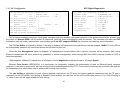
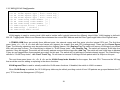
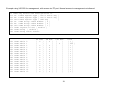
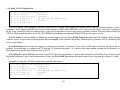
USER MANUAL FRM220-100M(S) Fast Ethernet OAM/IP Web Smart Media Converter CTC Union Technologies Co., Ltd. Far Eastern Vienna Technology Center (Neihu Technology Park) 8F, No. 60 Zhouzi St., Neihu, Taipei 114, Taiwan T +886-2-26591021 F +886-2-26590237 E [email protected] [email protected] [email protected] H www.ctcu.com FRM220-100M(S) Operation Manual Fast Ethernet OAM/IP Web Smart Media Converter Version 1.0 December 5, 2011 (First Release) Version 1.01 March 14, 2012 (update) This Manual supports the following models: FRM220-100M : 1x100Base-FX + 1x10/100Base-TX FRM220-100MS : 1x100Base-FX (SFP) + 1x10/100Base-TX 2011-2012 CTC Union Technologies Co., LTD. All trademarks are the property of their respective owners. Technical information in this document is subject to change without notice. 3 Legal The information in this publication has been carefully checked and is believed to be entirely accurate at the time of publication. CTC Union Technologies assumes no responsibility, however, for possible errors or omissions, or for any consequences resulting from the use of the information contained herein. CTC Union Technologies reserves the right to make changes in its products or product specifications with the intent to improve function or design at any time and without notice and is not required to update this documentation to reflect such changes. CTC Union Technologies makes no warranty, representation, or guarantee regarding the suitability of its products for any particular purpose, nor does CTC Union assume any liability arising out of the application or use of any product and specifically disclaims any and all liability, including without limitation any consequential or incidental damages. CTC Union products are not designed, intended, or authorized for use in systems or applications intended to support or sustain life, or for any other application in which the failure of the product could create a situation where personal injury or death may occur. Should the Buyer purchase or use a CTC Union product for any such unintended or unauthorized application, the Buyer shall indemnify and hold CTC Union Technologies and its officers, employees, subsidiaries, affiliates, and distributors harmless against all claims, costs, damages, expenses, and reasonable attorney fees arising out of, either directly or indirectly, any claim of personal injury or death that may be associated with such unintended or unauthorized use, even if such claim alleges that CTC Union Technologies was negligent regarding the design or manufacture of said product. TRADEMARKS Microsoft is a registered trademark of Microsoft Corp. HyperTerminal™ is a registered trademark of Hilgraeve Inc. FCC WARNING: This equipment has been tested and found to comply with the limits for a Class A digital device, pursuant to Part 15 of the FCC Rules. These limits are designed to provide reasonable protection against harmful interference when the equipment is operated in a commercial environment. This equipment generates, uses, and can radiate radio frequency energy and if not installed and used in accordance with the instruction manual may cause harmful interference in which case the user will be required to correct the interference at his own expense. NOTICE: (1) The changes or modifications not expressively approved by the party responsible for compliance could void the user's authority to operate the equipment. (2) Shielded interface cables and AC power cord, if any, must be used in order to comply with the emission limits. CISPR PUB.22 Class A COMPLIANCE: This device complies with EMC directive of the European Community and meets or exceeds the following technical standard. EN 55022 - Limits and Methods of Measurement of Radio Interference Characteristics of Information Technology Equipment. This device complies with CISPR Class A. CE NOTICE Marking by the symbol CE indicates compliance of this equipment to the EMC and LVD directives of the European Community. Such marking is indicative that this equipment meets or exceeds the following technical standards: EN 55022:2006, Class A, EN55024:1998+A1:2001+A2:2003, and EN60950-1:2001 4 Table of Contents CHAPTER 1 INTRODUCTION ................................................................................................................................................................................................7 1.1 WELCOME .................................................................................................................................................................................................................................7 1.2 PRODUCT DESCRIPTION ................................................................................................................................................................................................................7 1.3 PRODUCT FEATURES ....................................................................................................................................................................................................................8 1.4 SPECIFICATIONS ..........................................................................................................................................................................................................................9 1.5 MANAGEMENT FEATURES .............................................................................................................................................................................................................9 1.6 PANEL .....................................................................................................................................................................................................................................10 CHAPTER 2 INSTALLATION ................................................................................................................................................................................................11 2.1 CHASSIS OPTIONS......................................................................................................................................................................................................................11 2.2 ELECTRICAL INSTALLATION...........................................................................................................................................................................................................12 2.3 INSTALLATION OF SFP MODULES .................................................................................................................................................................................................12 2.3.1 Inserting a Bale Clasp SFP Module into the Cage .........................................................................................................................................................12 2.3.2 Removing a Bale Clasp SFP Module..............................................................................................................................................................................12 CHAPTER 3 PROVISIONING ...............................................................................................................................................................................................13 3.1 CONSOLE LOGIN........................................................................................................................................................................................................................13 3.1.0 Console Main Menu ......................................................................................................................................................................................................13 3.1.1 UTP Configuration.........................................................................................................................................................................................................14 3.1.2 FX Configuration ...........................................................................................................................................................................................................15 3.1.3 Device Configuration.....................................................................................................................................................................................................16 3.1.4 802.ah Configuration ....................................................................................................................................................................................................17 3.1.5 802.1Q VLAN Configuration..........................................................................................................................................................................................18 3.1.6 QinQ VLAN Configuration .............................................................................................................................................................................................20 3.1.7 IP Address Configuration ..............................................................................................................................................................................................21 3.1.8 Converter Configuration ...............................................................................................................................................................................................22 3.1.9 Password Setting ..........................................................................................................................................................................................................24 5 3.2 WEB LOGIN .............................................................................................................................................................................................................................25 3.2.1 Introduction ..................................................................................................................................................................................................................25 3.2.2 Web Login Page ............................................................................................................................................................................................................25 3.2.3 Web Main Page ............................................................................................................................................................................................................26 3.2.4 System Information, Network Information...................................................................................................................................................................27 3.2.5 System Information, DD Information............................................................................................................................................................................28 3.2.6 Local Settings ................................................................................................................................................................................................................28 3.2.7 Remote Settings ............................................................................................................................................................................................................35 3.2.8 802.3ah OAM Functions ...............................................................................................................................................................................................35 3.2.9 Tools..............................................................................................................................................................................................................................40 3.2.10 Logout .........................................................................................................................................................................................................................43 3.3 TROUBLESHOOTING ...................................................................................................................................................................................................................43 3.3.1 Factory Default. ............................................................................................................................................................................................................43 3.3.2 LED Observations ..........................................................................................................................................................................................................44 3.3.3 Operation Checks ..........................................................................................................................................................................................................44 6 Chapter 1 Introduction 1.1 Welcome Thank you for choosing FRM220-100M(S) Fast Ethernet OAM/IP Web Smart Media Converter. Throughout this document, the two different models of this family will be referred to as FRM220-100M or in an abbreviated form as just 100M. If you would like to skip right to the installation of the converter, proceed to Chapter 2. This manual is used to explain the hardware installation procedures and operation of FRM220-100M, and present its capabilities and specifications. This manual is divided into 3 chapters, the Introduction, Installatio, and Provisioning Chapters. Installers should carefully read the Chapters 1&2, Introduction and Installation. The companion document, FRM220 NMC Configuration Manual, is also available in electronic format, and is required when this product is used FRM220 rack with NMC. The divisions in that manual are intended for use by personnel to answer questions in general areas. Planners and potential purchasers may read the Introduction to determine the suitability of the product to its intended use; Operating Personnel would use the Console and Web Based Management Chapters and Appendices to become familiar with the line cards and settings. Network Administrators should read the chapters on Console, Web Based Management and Trouble Shooting to become familiar with the diagnostic capabilities, network settings and management strategies for both stand-alone or within the SNMP managed chassis. 1.2 Product Description FRM220-100M is an electrical to optical media converter for Fast Ethernet. There are two models, one with fixed optical transceiver (100M) and one supporting pluggable SFP transceiver (100MS). These converters sport embedded stand-alone Web based management over IP networks as well as IEEE802.3ah OAM for remote in-band management. They are also fully compatible and manageable when placed in FRM220 managed chassis such as the CH20 or CH08 with NMC card. FRM220-100M(S) is an IEEE802.3ah OAM compliant copper to fiber Fast Ethernet solution designed to make conversion between 10/100Base-TX and 100Base-FX with SC, FC ,ST connector (FRM220-100M) or SFP LC connector (FRM220-100MS). When deployed as a stand-alone solution, this media converter incorporates an easy to use Web user interface for operation, administration and maintenance of both local and remotely connected FRM220-100M converters. By offering 802.3ah OAM compliance, this converter can be linked to any 802.3ah compliant fiber switch and support loop back and dying gasp functions. When placed in our centrally controlled and managed FRM220 managed rack, all functions of this converter and the remotely connected converter can be configured and monitored via in-band management, including band-width control, duplex, speed, VLAN configuration and more. 7 1.3 Product Features Auto-Cross over for MDI/MDIX at UTP port Auto-Negotiation or Forced Manual mode for UTP port Supports 802.3X flow control Enable or Disable Supports Jumbo Frames up to 9K bytes Supports 16 Tag VLAN Groups Supports 802.1Q tagging and 802.1ad double VLAN tag (Q-in-Q) Ingress/Egress Bandwidth control with 64K granularity Supports 802.3ah-OAM loop back and dying gasp (remote power failure detection) Supports firmware upgrade via Web Supports Digital Diagnostics (DOM) for supported SFP Provides product information for management Includes RMON counters (stand-alone only) Supports password setting for authentication Supports Link Fault Pass Through (LFP) Function Supports Auto Laser Shutdown (ALS) Function Supports DHCP client for automatic TCP/IP configuration Supports local and in-band remote management from FRM220 rack management FRM220-100MS SFP socket supports a wide range of standard SFP modules to address any network situation. Single-mode, Multi-mode, Multi-rate, Single fiber bi-directional, Coarse and Dense Wave Division Multiplexing (CWDM and DWDM) and Copper media WARNING: Fiber optic equipment may emit laser or infrared light that can injure your eyes. Never look into an optical fiber or connector port. Always assume that fiber optic cables are connected to an active laser light source. 8 1.4 Specifications Optical Interface Connector Data rate Duplex mode Fiber Distance Wavelength Electrical Interface Connector Data rate Duplex mode Cable Distance Indications Power Input Consumption Dimensions Weight Temperature Humidity Certification MTBF SFP cage (100MS) or Duplex SC, ST, FC (100M) 100Base-FX (125Mbps optical rate) Full duplex on fiber Depends on SFP Depends on SFP Depends on SFP RJ-45, shielded auto, 10mbps (10Base) or 100mbps (100Base) auto, Full or Half Cat 5 or better 100meters maximum LED (PWR, FX Link, LAN Link, LAN Speed) (Card supports hot-swapping) Card : 12VDC, Standalone : AC, DC options <4W 155 x 88 x 23mm (D x W x H) 110g 0 ~ 60°C (Operating), -10 ~ 70°C (Storage) 10 ~ 90% non-condensing CE (EMI/LVD), FCC, RoHS Compliant 75000 hrs 1.5 Management Features Both models may be placed in a stand-alone chassis with console port, allowing support of a text based serial terminal with an easy to use menu system for configuration. Once configured for TCP/IP access, they also support a Web Smart GUI for intuitive setting via point & click. When placed in FRM220 managed chassis, the card is configured and monitored through the chassis NMC (network management controller) via console, Telnet, Web HTTP or SNMP. 9 1.6 Panel 1 x SFP port, supports any 155M transceiver Fixed Optical Transceiver Power The LAN Speed LED when green indicates 100M speed. When off, the LED indicates a 10Base-T speed. LAN Lnk FX Link LED Indicators Lan Speed Factory reset procedure Apply power to 100M(S). Allow 30 seconds to fully boot. Using a pencil or ball-point pen, press the 'DEFAULT' recessed push-button switch (located on the face plate) and hold for 6 seconds. The unit will be restored to factory default almost immediately. The defaults are: DEFAULT: Use to recover from lost password or to return all settings to factory default values. Figure 1. Panel Graphics IP=10.1.1.1 netmask=255.255.255.0 GW=10.1.1.254 password reset to 'admin' 10 Chapter 2 Installation 2.1 Chassis Options Note: This converter card can be placed in any FRM220 series chassis, including the single slot CH01 or CH01M, two slot CH02M or CH02-NMC, the eight slot CH08 or the full twenty slot CH20 chassis. Chassis with built-in power are available with single AC (90-240VAC), single DC (18~75VDC), dual AC, dual DC or AC plus DC combo. The single slot chassis with external power adapter works with AC source voltage only with the provided 90~240VAC 12VDC@400mA switching adapter. FRM220-CH20 CH02-NMC-XX Chassis (XX= AC, DC, AA, DD or AD) CH01-XX Chassis (XX= AC, DC, AA, DD or AD) FRM220-CH01, single slot chassis Requires external AC to DC 12V switching adapter. Follow all ESD precautions when handling the card and SFP modules. 11 2.2 Electrical Installation With a built-in AC power chassis, AC power is supplied to the chassis through a standard IEC C14 3-prong receptacle, located on the rear of the chassis. Any national power cord with IEC C13 line plug may be used to connect AC power to the power module. With a built-in DC power chassis, DC -48V is connected to the terminal block located on the rear of the chassis, observing the proper polarity. The chassis should always be grounded through the protective earth lead of the power cable in AC installations, or via the frame ground connection for DC installations. Left: Live line Right: Neutral line Middle: Ground DC IN -V FG +V Left: -V (-48V) Right: +V (0V) Middle: Frame Ground 18~75 VDC 2.3 Installation of SFP Modules CTC Union supplied SFP modules are of the Bale Clasp type. The bale clasp pluggable module has a bale clasp that secures the module into the SFP cage. 2.3.1 Inserting a Bale Clasp SFP Module into the Cage Step 1 Close the bale clasp upward before inserting the pluggable module. Step 2 Line up the SFP module with the port, and slide it into the cage. Seat it. Attach fiber cable. 2.3.2 Removing a Bale Clasp SFP Module Step 1 Remove fiber cable. Open the bale clasp on the SFP module. Press the clasp downward with your index finger. Step 2 Grasp the SFP module between your thumb and index finger and carefully remove it from the SFP cage. 12 Chapter 3 Provisioning 3.1 Console Login Connect a serial terminal to CH01M DB9 and configure the terminal emulation for 38.4k, 8bit, no parity, 1 stop and no flow control. After powering on, the 100M will have fully booted within 25 seconds. The factory default password is ‘admin’. ***************************************** *** CTC UNION TECHNOLOGIES CO.,LTD *** *** FRM220-100MS Manager *** ***************************************** Model:[FRM220-100MS ] Ver:[1.000-1.000-0.000-0.000] [ Local ] User Name : admin Password : [CH-01M ] [CH-01M ] 3.1.0 Console Main Menu ***************************************** *** CTC UNION TECHNOLOGIES CO.,LTD *** *** FRM220-100M Manager Ver:1.00 *** ***************************************** Model:[FRM220-100M ] Ver:[1.000-1.000-0.000-0.000] [ Local ] <1> UTP Status and Configure <2> FX Status and Configure <3> Device Status and Configure <4> 802.3ah Status and Configure <5> VLANTag Status and Configure <6> Q-in-Q Status and Configure <7> IP Status and Configure <8> Converter Status and Configure <P> Password change 13 3.1.1 UTP Configuration << UTP Status and Configuration <1> Port Active [ Enable ] <2> Negotiation [ Auto ] <3> Speed [ 100 ] <4> Duplex [ Full ] <5> Flow Control[ Enable ] <6> Egress Limit [ Disable ] <7> Ingress Limit [ Disable ] >> Link [ Link Up ] Status [ 100 ] Status [ Full ] The UTP Port Active is enabled by default. If the port is disabled, all transmission through this port will be stopped. 100M’s LAN Link LED will be extinguished, however any connected device will still detect an Ethernet link. The UTP port supports auto-negotiation per IEEE802.3u as well as manual forced mode setting of Speed (10/100) and Duplex (Half/Full). In 802.3u, speed can be auto detected, however the Duplex mode MUST be negotiated. When an 802.3u compliant device is configured in auto negotiation mode, failure to negotiate Duplex (for example, if connected to legacy equipment or to equipment configured in forced mode) will result in the Auto device assuming a Half-Duplex operating mode. Do not connect forced Full mode Ethernet ports to an auto device as this will result in a Duplex-Mismatch. Ethernet Flow Control (IEEE802.3X) is a mechanism for temporarily stopping the transmission of data on Ethernet family computer networks. It can work in conjunction with rate limiting to avoid dropped packets from TCP. Flow control should also be used with care and with full knowledge of its effect when used to pause traffic coming from a switch. The rate limiting is adjustable for both ingress (packets received into the TP port) and egress (packets transmitted from the TP port) in granularity of 64k. By default, rate limiting is disabled. Once enabled, the rate limit can be set in nx64k rates where n=1 to 1600. Entering an “n” value of zero (0) will again disable the rate limiting. 14 SFP Digital Diagnostics 3.1.2 FX Configuration << <1> <2> <3> <5> <6> <7> <8> FX Status and Configuration >> FX Link [ UP ] Remote PWR [ OK ] SFP [ Yes ] D/D Function [ No ] Port Active [ Enable ] Management [ Enable ] Negotiation [ Force ] Speed [ 100 ] Status [ 100 Flow Control[ Enable ] Egress Limit [ Disable ] Ingress Limit [ Disable ] SFP Digital Diagnostics ] << Fiber D/D Function Status >> Vendor Name :[ FIBERXON INC. Vendor Part Number :[ FTM-3125C-L40 Fiber Type :[ Single ] Wave Length :[ 1310 nm ] Link Length :[ 0040 Km ] Tx Power :[ 01 dBm] Rx Power :[-12 dBm] Rx Sensitivity :[ 00 dBm] Temperature :[ 046 C ] ] ] This converter supports receiving a ‘dying gasp’ indication from the remotely connected converter. If the remote should suffer a power loss, the status of “Remote PWR” will be shown as ‘Abnormal’ (802.3ah must be enabled in both converters). This converter can also read SFP information such as model, manufacturer, part number and if the SFP supports DDOM, the converter can read this extra information. The FX Port Active is enabled by default. If the port is disabled, all transmission through this port will be stopped. 100M’s FX Link LED will be extinguished; however any connected device will still detect a fiber link. When the fiber Management option is disabled, all management communication with a remote converter will be stopped. Only normal Ethernet transmission will occur without any possibility of remote management, either through 802.3ah OAM or through chassis to CPE inband management. 100M supports 100Base-FX speed only at full duplex. So this Negotiation is always forced to 100 mbps Speed. Ethernet Flow Control (IEEE802.3X) is a mechanism for temporarily stopping the transmission of data on Ethernet family computer networks. It can work in conjunction with rate limiting to avoid dropped packets from TCP. Flow control should also be used with care and with full knowledge of its effect when used to pause traffic coming from a switch. The rate limiting is adjustable for both ingress (packets received into the TP port) and egress (packets transmitted from the TP port) in granularity of 64k. By default, rate limiting is disabled. Once enabled, the rate limit can be set in nx64k rates where n=1 to 1600. Entering an “n” value of zero (0) will again disable the rate limiting. 15 3.1.3 Device Configuration << Device Status and Configuration >> <1> Device Active [ Enable ] <2> DHCP Client [ Disable ] <3> Auto Laser Shutdown [ Disable ] <4> Link Fault Pass-Through [ Disable ] <5> Port Reset <6> Factory Default <7> Store Parameters By default, the Device Active is enabled. If device is disabled, all activity in the device will be stopped. 100M’s LAN and FX Link LEDs will be extinguished; however any connected device will still detect UTP and fiber link. This device supports TCP/IP auto-configuration through DHCP service. By default the DHCP Client function is disabled. Auto Laser Shutdown is a safety mechanism that will disable laser output when no received optical signal is sensed. By default, ALS is disabled. Link Fault Pass-Through or LFP is a method of forwarding a link loss from copper to fiber or from fiber to copper. It is disabled by default, but it can be enabled here. Port Reset will reset the switch, should something as unlikely as the switch hanging occurring. Factory Default will load all the original factory default settings. This is a good way to get transmission working again if there are many VLAN or Q-in-Q settings done but the converter needs to be reset to default with all those functions disabled. IMPORTANT The Store Parameter item will write configuration to flash. After any configuration changes are made to the converter, they must be saved or the previous settings will be in effect after the next reboot. 16 3.1.4 802.ah Configuration << 802.3ah Status and Configuration >> <1> 802.3ah Active [ Enable ] <2> 802.3ah mode [ Active ] <3> Link Event [ Enable ] <4> Loop Back [ Enable ] <5> Loop Back Number [ 10 ] <6> Loop Back Frame Size[ 1500 ] <7> Loop Back Test Start Loop Back Status [ OK ] This converter supports IEEE 802.3ah, an OAM protocol that operates at Ethernet Layer 2 (Data Link layer). OAM provides mechanisms to monitor link operation/health and to improve fault isolation. OAM only works point-to-point over the fiber link. In addition to standard 802.3ah functions like loop back and dying gasp, FRM220-100M also implements OAM to provide complete provisioning of the remote fiber connected converter, without using Layer 3 IP protocol. By using OAM, we can remote manage another fiber connected 100M(S) converter, without IP addressing. From this menu we can also perform some basic diagnostics, such as loop back test. To use the OAM functions, the 802.3ah Active setting must be enabled. The 802.3ah mode is used to configure an OAM pair. In a pair, one unit must be ‘active’, while the other must be ‘passive’. We typically place the remote converter in ‘passive’ mode and make the local converter ‘active’. In order to do Loop Back test, the option must be enabled in both converters. This is a non-intrusive test which uses OAM packets and will not affect normal transmissions. The number of OAM frames used (the number of times the loop back is done) is set by the Loop Back Number. The Loop Back Frame Size controls the packet size of the OAM frames used for loop back testing. The default is 1500 bytes. The Loop Back Test Start item is just what it says. Use the “7” key to toggle the test on and off. The result of the test will be shown as either “OK” (pass) or “Fail”. 17 3.1.5 802.1Q VLAN Configuration << VLAN Tag Status and Configuration >> <1> TP Frame Egress Type [ Don't Touch Tag ] <2> FX Frame Egress Type [ Don't Touch Tag ] <3> CPU Frame Egress Type [ Don't Touch Tag ] <4> TP VLAN Group Index Number [ 0 ] <5> FX VLAN Group Index Number [ 0 ] <6> CPU VLAN Group Index Number [ 0 ] <7> VLAN Ingress Filter [ Disable ] <8> VLAN Group [ Disable ] <9> VLAN Group Table Status VLAN tagging is used to create virtual LANs and to isolate traffic logically between the different virtual LANs. VLAN tagging is defined in 802.1Q. Tagging adds 32bits to an Ethernet frame between the source MAC address and the EtherType/Length fields of the original frame. In FRM220-100M there are actually three different ports, the external copper and fiber ports, plus the internal CPU port. The first three menu items, <1>, <2>, & <3> deal with how frames exit (egress) the copper, fiber and CPU (management). These are the Frame Egress Type. The following operations may be performed to the outgoing frames: <1>: Replace Tag The switch will remove VLAN tags from packets then add new tags to them. The inserted tag is defined in ”VLAN Group Index”. <2>: Remove Tag The switch will remove VLAN tags from packets, if they are tagged. The switch will not modify packets received without tags <3>: Add Tag The switch will add VLAN tags to packets, if they are not tagged when these packets are output on this port. The switch will not add tags to packets already tagged. The inserted tag is defined in ”VLAN Group Index”. <4>: Don't Touch Tag Do not insert or remove VLAN tags to/from packet which is output on this port. The next three menu items <4>, <5>, & <6> are the VLAN Group Index Number for the copper, fiber and CPU. These are the VID tags that would be used for adding or replacing in the above functions. VLAN Ingress Filter is used to actually enable the VLAN aware functions. If disabled, the switch is VLAN un-aware. When VLAN Group is enabled, the 16 VLAN group table may be edited, providing control of how VID packets are grouped between the FX port, TP Port and the Management (CPU) port. 18 Example using VID 555 for management, with access via TP port. Normal access to management not allowed. << VLAN Tag Status and Configuration >> <1> TP Frame Egress Type [ Don't Touch Tag ] <2> FX Frame Egress Type [ Don't Touch Tag ] <3> CPU Frame Egress Type [ Add Tag ] <4> TP VLAN Group Index Number [ 0 ] <5> FX VLAN Group Index Number [ 0 ] <6> CPU VLAN Group Index Number [ 1 ] <7> VLAN Ingress Filter [ Enable ] <8> VLAN Group [ Enable ] <9> VLAN Group Table Status <0> <1> <2> <3> <4> <5> <6> <7> <8> <9> <a> <b> <c> <d> <e> <f> VLAN VLAN VLAN VLAN VLAN VLAN VLAN VLAN VLAN VLAN VLAN VLAN VLAN VLAN VLAN VLAN Table Table Table Table Table Table Table Table Table Table Table Table Table Table Table Table 0 1 2 3 4 5 6 7 8 9 10 11 12 13 14 15 TP [ [ [ [ [ [ [ [ [ [ [ [ [ [ [ [ mem V ] ] V ] V ] V ] V ] V ] V ] V ] V ] V ] V ] V ] V ] V ] V ] FX [ [ [ [ [ [ [ [ [ [ [ [ [ [ [ [ mem V ] ] V ] V ] V ] V ] V ] V ] V ] V ] V ] V ] V ] V ] V ] V ] CPU mem [ ] [ V ] [ ] [ ] [ ] [ ] [ ] [ ] [ ] [ ] [ ] [ ] [ ] [ ] [ ] [ ] 19 PVID [ 1 ] [ 555 ] [ 1 ] [ 1 ] [ 1 ] [ 1 ] [ 1 ] [ 1 ] [ 1 ] [ 1 ] [ 1 ] [ 1 ] [ 1 ] [ 1 ] [ 1 ] [ 1 ] 3.1.6 QinQ VLAN Configuration << Q in Q Status and Configuration >> <1> Q in Q Active [ Disable ] <2> Q in Q Tag Priority [ Internal ] <3> Q in Q Direction [ TP add tag ,FX Remove tag ] <4> Q in Q Tag ID [ 0x8100 ] <5> Q in Q VID Tag [ 1 ] Q in Q or double VLAN tagging is defined in IEEE802.1ad. Double VLAN tagging is required when a service provider wishes to carry a customer’s VLAN tagged traffic through its own VLAN network. In MEF (Metro Ethernet Forum) terms, the first tag or “inner tag” is referred to as the C-tag (customer) while the second tag or “outer tag” is referred to as the S-tag (service provider). Normal VLAN tag has an EtherType (TPID or Tag Protocol Identifier) of 0x8100. The IEEE802.1ad standard recommends 0x88a8 TPID for the outer or S-tag. Q in Q Active is used to enable or disable the double tagging function. Q in Q Tag Priority provides the QoS method. When selecting ‘Internal’ priority, the three bit VLAN tag priority bits are mapped to the internal 2-bit priority. When selecting ‘Remark’ 802.1P remarking QOS will be used instead. Q in Q Direction sets up how the tagging is carried from provider to customer. If this were a CPE device with fiber facing the service provider, we would want to configure the FX add tag ,TP Remove tag option. i.e., add the outer tag heading towards service provider (out fiber) and remove the S-tag at customer side (out TP). Q in Q Tag ID is what IEEE802.1ad refers to as TPID (Tag Protocol Identifier) or what is also referred to as the EtherType. These 2 octets follow the S-tag and C-tag in the Ethernet frame. Finally, the Q in Q VID Tag assigns the actual value to the S-tag from the range of 1~4094. Example of S-tag with VID 999 configured at customer side device. << Q in Q Status and Configuration >> <1> Q in Q Active [ Enable ] <2> Q in Q Tag Priority [ Internal ] <3> Q in Q Direction [ FX add tag ,TP Remove tag ] <4> Q in Q Tag ID [ 0x88a8 ] <5> Q in Q VID Tag [ 999 ] 20 3.1.7 IP Address Configuration ***************************************** *** CTC UNION TECHNOLOGIES CO.,LTD *** *** FRM220-100MS Manager *** ***************************************** Model:[FRM220-100MS ] Ver:[1.000-1.000-0.000-0.000] [ Local ] MAC [ 00:02:ab:03:04:05 ] <1> IP Address [ 10.1.1.1 ] <2> Subnet Mask [ 255.255.255.0 ] <3> Gateway [ 10.1.1.254 ] [CH-01M ] The above shows the factory default TCP/IP settings for FRM220-100M(S). IP Address is the dotted/decimal format for the IPv4 address to remotely manage this device. The Subnet Mask defines the type of subnet the device will be on. The proper subnet setting will be defined by the network administrator. The Gateway is the default path for any packets NOT belonging to the local subnet. This IP address is the address of the router on your network. It is also entered as a dotted/decimal IPv4 format address. If the device will only be managed on the local subnet, setting a gateway address is not necessary. Do not forget to save the configuration under the ‘Device’ menu so that the settings are permanent. 21 3.1.8 Converter Configuration << Converter Status and Configuration >> <1> Jumbo Frame [ Disable ] <2> Forward CRC Frame [ Disable ] <3> Forward Pause Frame [ Disable ] <4> Qos Priority [ Enable ] <5> Broadcast Storm Filter [ Disable ] <6> Multicast Storm Filter [ Disable ] <7> Unknown DA Unicast Storm Filter [ Disable ] The Converter configuration menu includes special features of FRM220-100M. This converter is capable of supporting Jumbo Frames (9k byte packets) when this option is enabled. Note that in order to support jumbo frames, the TP speed and duplex must match the FX. i.e., 100M/Full. Jumbo Frames are not typically used on a normal network, since most devices are not able to handle them and they would be truncated. Most PCs, servers, switches, DSL and WiFi do not support jumbo frames. Jumbo frames can only work on a pure Jumbo frame network, which currently only exists in data centers for server-to-server or server-tostorage connections and on some back bone networks. Jumbo frames will always be considered to be illegal, non-standard Ethernet packets, according to IEEE802.3. In most cases, the call for jumbo frame support is just marketing hype. Forward CRC Frame option is disabled by default. The normal behavior of a switch is to read the entire Ethernet frame (store), calculate the check sum and compare to the FCS in the packet. If the checksum matches, the packet is transmitted (&forward). If the checksum does not match, the switch considers the packet to have CRC error and drops it. If this option is enabled, the packet with CRC error will still be forwarded instead of being dropped. The option Forward Pause Frame allows pause frame forwarding to occur when enabled. Pause frames are special broadcast frames defined in IEEE802.3X. Normally pause frames are used by the switch to throttle packets through a bottle neck rather than drop excess packets (for example, if 100M data stream is exiting a lower speed 10M port). Normally, the pause frames are not forwarded between interfaces in the switch. 22 Quality of service is the ability to provide different priority levels to different applications, users, or data, or to guarantee a certain level of performance for data. Real time applications benefit the most when a system of QoS is employed. Examples are for voice and video over IP. In Ethernet, QoS is dependent on VLAN tagged packets. This is because the QoS priority bits (3 bits) are included in the VLAN tag. Without VLAN tags, there are no priority bits, and no way to set QoS Priority. In FRM220-100M, QoS Priority is enabled by default, but if there are no VLAN tagged packets, the enabled setting is meaningless. Broadcast Storm is a condition where either a loop exists on the network or an Ethernet transceiver is bad and exhibiting jabber. In addition there are the deliberate attempts to bring a network down through virus and denial of service routines. When enabled, the Broadcast Storm Filter will recognize and block the forwarding of these broadcasts. Multicast storms happen when application participants request retransmits of information they have missed in the multicast stream. There are many applications, like video streaming, IP based punch clocks, IP based surveillance trackers and camera, that come with multicast or some broadcast based protocol turned on by default. The Multicast Storm Filter can be enabled to filter these unwanted effects. The Unknown DA Unicast Storm Filter can be used to filter the Unicast broadcasts whose objective is to cause deny-of-service. Some Trojans and virus start scanning multicast IP ranges causing excess broadcasts and reducing network performance. 23 3.1.9 Password Setting Model:[FRM220-100MS [ Local ] <1> UTP Status <2> FX Status <3> Device Status <4> 802.3ah Status <5> VLANTag Status <6> Q-in-Q Status <7> IP Status <8> Converter Status <P> Password change ] Ver:[1.000-1.000-0.000-0.000] and and and and and and and and [CH-01M ] Configure Configure Configure Configure Configure Configure Configure Configure --------------------------------------------------Please Keyin Old Password:***** Please Keyin New Password:***** Please Keyin Cfm Password:***** The password setting protects FRM220-100M against unauthorized access to the management from serial console and HTTP. To change the password, select “p” from the main menu, next key in the old password and then key in the new password twice. If the password is lost or forgotten, FRM220-100M must be set to factory default by using the front panel push button. With the unit already fully booted, press the default pushbutton with a pencil or ball point pen tip and hold for 6 seconds, then release. The password will be reset to ‘admin’ and all default IP and internal settings will be restored to factory defaults. 24 3.2 Web Login 3.2.1 Introduction In an effort to make Networking devices easier to configure, many devices can now be configured via a Web Page, which should be familiar to all Internet users. The web page is accessed by the Default IP Address of the device from a Web Browser such as Internet Explorer or Firefox in the following way: 10.1.1.1/ (Assuming the Default IP Address is 10.1.1.1 ) Before accessing this device by web browser, the IP address must be known or it must be reset or changed to be used on the desired network. Please refer to Chapter 1, section 1.6 or to Chapter 2, section 3.1.9 for the factory reset procedure. To configure the IP address via console, refer to Chapter 3, section 3.1.7 for IP Address settings. If you do not have ability to access the console configuration, then you must set your PC to the default IP subnet and access this device that way. Then you can change the IP address through the web interface. 3.2.2 Web Login Page Access the device via a web browser. Enter the password and click “Login”. 25 3.2.3 Web Main Page 26 3.2.4 System Information, Network Information The information displayed on this page gives specific device, network information, and port status for the local FRM220-100M and for any remote that is accessible via IEEE802.3ah OAM in-band management. 27 3.2.5 System Information, DD Information The DD or DDOM information is read from the MSA compliant SFP module and can be displayed via the web user interface. 3.2.6 Local Settings If you have reviewed section 3.1 of this chapter, then you will already be familiar with these settings and their actions. We will go through the settings here again, but not with as much detail. For detail, please review section 3.1. 28 3.2.6.1 IP Configuration Use this screen to set the TCP/IP configuration for the local unit. Note, that if you change the IP address you could lose remote management for this device. Remember to save settings under the “Tools” menu. 3.2.6.2 Password Setting Key in the current password and type in the new password twice, then click the “Apply” button. 29 3.2.6.3 Converter Configuration All of these special functions are explained in Section 3.1.8 of this chapter. Select the proper radio buttons and the click the “Apply” button. Remember to save settings under the “Tools” menu. 30 3.2.6.4 Port Configuration This screen is for the configuration of the electrical Ethernet port (TP) and the optical port (FX). The options include enabling or disabling the port, setting auto or forced Ethernet mode, enabling 802.3X, and setting ingress and egress rate limiting. Note that rate limiting has a granularity of 64K so the rate can be set from 64k to 100M in 64K steps. 3.2.6.5 Q‐in‐Q Configuration The Q-in-Q function sets the S-tag or outer VLAN tag which is typically used by the service provider. For more explanation please see Section 3.1.6. 31 3.2.6.6 RMON Counters The counters have an accumulation of received bytes for each port (UTP, Fiber and Management) and more detailed distribution of those packets 32 3.2.6.7 VLAN Group Configuration FRM220-100M supports up to 16 VLAN groups. By using the check boxes for each port, the access to different VIDs can be controlled. 33 3.2.6.8 VLAN Per Port Configuration In FRM220-100M there are actually three different ports, the external copper and fiber ports, plus the internal CPU port. The VLAN Per Port Setting page deals with how frames exit (egress) the copper, fiber and CPU (management). These are the Frame Egress Type. The following operations may be performed to the outgoing frames: <1>: Replace Tag The switch will remove VLAN tags from packets then add new tags to them. The inserted tag is defined in ”VLAN Group Index”. <2>: Remove Tag The switch will remove VLAN tags from packets, if they are tagged. The switch will not modify packets received without tags <3>: Add Tag The switch will add VLAN tags to packets, if they are not tagged when these packets are output on this port. The switch will not add tags to packets already tagged. The inserted tag is defined in ”VLAN Group Index”. <4>: Don't Touch Tag Do not insert or remove VLAN tags to/from packet which is output on this port. 3.2.6.9 Q in Q Configuration Q in Q or double VLAN tagging is defined in IEEE802.1ad. Double VLAN tagging is required when a service provider wishes to carry a customer’s VLAN tagged traffic through its own VLAN network. In MEF (Metro Ethernet Forum) terms, the first tag or “inner tag” is referred to as the C-tag (customer) while the second tag or “outer tag” is referred to as the S-tag (service provider). Normal VLAN tag has an EtherType (TPID or Tag Protocol Identifier) of 0x8100. The IEEE802.1ad standard recommends 0x88a8 TPID for the outer or S-tag. 34 3.2.7 Remote Settings When 802.3ah is active in both the local and remote unit (with fiber connection), the in-band management provides an embedded channel to control and configure the remote by using OAM (layer 2) Ethernet packets. The same settings available to the local unit are available under the Remote Setting menu, with the exception of password setting and Counters. 3.2.8 802.3ah OAM Functions This converter supports IEEE 802.3ah, an OAM protocol that operates at Ethernet Layer 2 (Data Link layer). OAM provides mechanisms to monitor link operation / health and to improve fault isolation. OAM only works point-to-point over the fiber link. In addition to standard 802.3ah functions like loop back and dying gasp, the 100M also implements OAM to provide complete provisioning of the remote fiber connected converter, without using Layer 3 IP protocol. By using OAM, we can remote manage another fiber connected 100M(S) converter, without IP addressing. From this menu we can also perform some basic diagnostics, such as loop back test. 35 3.2.8.1 802.3ah Configuration To use the OAM functions, the 802.3ah Functions setting must be enabled. It is not enabled by default. The 802.3ah Mode is used to configure an OAM pair. In a pair, one unit must be ‘active’, while the other must be ‘passive’. We typically place the remote converter (CPE) in ‘passive’ mode and make the local converter ‘active’. ‘Passive’ is the default setting when 802.3ah function is enabled. In order to do Remote Loop Back test, the option must be enabled in both converters. By default it is not enabled. The normal status when OAM is working is shown above. If OAM is not passing due to fiber disconnect, Discovery Status will be Fault. If OAM is not enabled, this status window will not even be shown. 36 3.2.8.2 Loop back Test The loop back test is a non-intrusive test which uses OAM packets and will not affect normal transmissions. The number of OAM frames used (the number of times the loop back is done) is set by the Send Packet Number. The default is 1 packet. The Packet Length (Not including CRC) controls the packet size of the OAM frames used for loop back testing. The default is 60 bytes. The CRC of Ethernet packets uses 4 bytes. Valid Ethernet packets range in size from 64 bytes to 1518 bytes. VLAN tag adds another 4 bytes for a maximum size of 1522 bytes. Q in Q adds yet another 4 bytes, bringing the packet size to 1526 bytes. Any frame size larger than this is technically called a jumbo frame. The Loop Back Test Start is accomplished by clicking the “Apply” button. 802.3ah is a slow protocol with a maximum speed of 10 packets per second. The test above takes 10 seconds for 100 packets. 37 3.2.8.3 802.3ah Status The Global Config fields display the state of OAM, if OAM is enabled. We can also see the MAC addresses of the local and remote units in the OAM manageable pair. The Flags Field list the results of individual events based on the results of OAM protocol data units (OAMPDUs). Lastly, when two OAM devices start negotiation, there is Discovery Information passed between them. The results are shown here. 38 Most information carried by OAMPDU is encoded using type-length-value (TLV) format. The first octet (or byte) of the OAMPDU indicates the type. This type is used to let the OAM client know how to decode the bytes containing the information. The next octet carries the length of the information. This display has TLV information for both the local and remote OAM units. Ethernet OAM also defines a set of standard event conditions that Ethernet links should monitor in normal operation, and if detected, should be signaled to a peer entity. The Link Event Notification Status conditions reflect a degraded, but not yet inoperable, Ethernet connection. These conditions include threshold-crossing alarms on the frequency of symbol errors and frame errors. 39 One of the most critical problems in an access network for carriers is differentiating between a simple power failure at the customer premise and an equipment or facility failure. Dying gasp provides this information by having a station indicate to the network that it is having a power failure. If remote management is lost, we simply need to check the Remote Dying Gasp Count register to see if it has been incremented. 3.2.9 Tools The Tools menu includes the System Reboot, Save and Restore settings and Firmware Upgrade functions. 40 3.2.9.1 System Reboot When the converter is rebooted, all counters and registers are cleared and the converter starts fresh. If OAM is enabled, the discovery process will start. After selecting the System Reboot menu item, a confirmation dialogue box will pop up. Click “OK” to reboot the converter or click “Cancel” to leave without rebooting. The converter requires about 20~25 seconds to fully reboot. 3.2.9.2 Save and Restore After performing configuration of the converter, the settings must be saved. Click the “Save To Flash” button to save settings. If you wish to abandon all settings and return to the previous settings before doing configuration, click the “Load From Flash” button. To restore all settings to factory default, click the “Reset To Factory” button. The IP address will also be reset, so you might lose management contact with the converter. So, be careful. 41 3.2.9.3 Firmware Upgrade If bugs are discovered, if functions are added, or if factory default settings are changed, the firmware in the converter will require upgrading. The only method to do upgrade for this converter is through the local Web (HTTP) user interface. The firmware image is uploaded from the browser (Post), it is checked for integrity, the flash is erased and then the flash is written with the new image. DO NOT LET ANY POWER INTERRUPTION OCCUR DURING THE UPGRADE PROCEDURE. Click the “Browse” button and locate the image upgrade file through the “Choose File to Upload” dialogue box, then click “Open”. Next, click the “Upgrade” button. The “Upload success!” indicates the image was transferred OK. Do not do anything for the next 60 seconds!!!!. After 60 seconds, you may click the link to re-login to the web interface. 42 3.2.10 Logout Logging out will ensure that the management session with FRM220-100M(S) is terminated. This is especially important if you are using a public computer to manage the device. Once logged out, a password must be entered to access FRM220-100M(S) again. Click the “OK” button to completely log out. Click the “Cancel” button to return to configuration of FRM220-100M(S). 3.3 Troubleshooting 3.3.1 Factory Default. Apply power to FRM220-100M and allow 25-30 seconds to fully boot. Using a pencil or ball-point pen, press the 'DEFAULT' recessed push-button switch (located on the face plate) and hold for 6 seconds or more then release. DO NOT POWER OFF; Allow the unit to again fully reboot (about 25 seconds). The factory default TCP/IP settings are: IP=10.1.1.1 netmask=255.255.255.0 GW=10.1.1.254 The username and password are both reset to 'admin'. Additionally, any VLAN, 1Q or Q in Q will be disabled. All ports will be enabled, UTP ports set for auto-negotiation and no bandwidth limiting on any port. 43 3.3.2 LED Observations 3.3.2.1 Power On At initial power on, PWR LED will be lit. Error conditions : If all LEDs immediately light and never turn off, or if no LED ever lights, then the card is possibly defective. Be sure to double check power source and try either another FRM220-100M in the same chassis or try the card in a different chassis. 3.3.2.2 UTP Link Test. Following a complete power and boot up (about 25 seconds) the converter will be active and LAN port will display LAN LNK state when connected to a live Ethernet circuit. The LAN SPD LED will be green when connected to Fast Ethernet (100M). When connected to 10Base-T the LAN SPD LED will be off. 3.3.2.3 Fiber Link Test Following a complete power and boot up (about 25 seconds) the converter will be active. For FRM220-100MS, place a known good SFP module into Fiber Port cage. Use a simplex patch cable (single fiber strand, LC to LC), route the SFP Tx back to the Rx optical connection. The FX LNK LED should light. For FRM220-100M, use a simplex patch cable (single fiber strand, SC to SC, ST to ST or FC to FC), route the Tx back to the Rx optical connection. The FX LNK LED should light. Caution: When performing a physical loop back on any fiber port, DO NOT connect the LAN port to a live Ethernet network. Doing so could create a broadcast storm. 3.3.3 Operation Checks 3.3.3.1 Converter Check A very easy way to ensure a pair of FRM220-100M is passing traffic, is to place them between two PCs. Connect PC1 to LAN of one converter and PC2 to LAN of the other converter. When the two PCs can ping each other, it indicates FRM220-100M pair is operational. 44 3.3.3.2 Console Check Connect a dumb terminal (or PC running terminal emulation) to the CONSOLE port of the CH01M one-slot chassis. Set the terminal configuration for 38.4K, 8bit, no parity, 1 stop and now flow control. When FRM220-100M is running normally, there should be a terminal display with either the main page or a password login prompt. If no terminal display, it indicates some internal problem with the unit. 3.3.3.3Ping Test With FRM220-100M reset to factory default, connect a PC and configure the PC to the 10.1.1.0 network (10.1.1.100 recommended). Use a PC to ping FRM220-100M at its factory default IP address of 10.1.1.1. With a direct connection to PC, there should be no time outs and ping latency should be less than 1 millisecond. If you switch to another FRM220-100M, be sure to clear the PC ARP table. Every FRM220-100M has the same default IP address, but every unit has a different MAC address. To clear the PC’s MAC table, open a command window and execute the command ‘arp –d’. In addition, if you disconnect the PC from any LAN connection and then re-connect, the ARP table should also be cleared. 3.3.3.4 Web Access Test With FRM220-100M reset to factory default, connect a PC and configure the PC to the 10.1.1.0 network (10.1.1.100 recommended). Use a PC to connect to FRM220-100M at its factory default IP address of 10.1.1.1 using a web browser (Internet Explorer, Firefox, Chrome, etc.). The local web page login page should display. Use ‘admin/admin’ to login; the local main page should be displayed in the browser. If the ping test can pass and the login page can be displayed but login fails, we recommend that cookies be deleted. You may either delete all cookies for your browser or only the individual cookie created for the IP address of FRM220-100M. 45