1
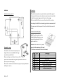
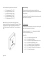
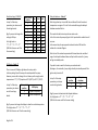
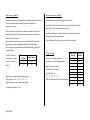
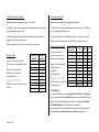
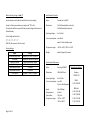
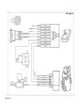
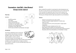
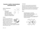
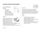
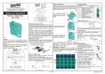
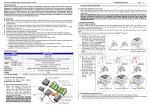
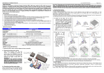
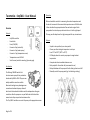
Tecomotive - tinyCWA – User Manual Operation Overview When activated the controller is measuring the coolant temperature and the rate of increase with the connected temperature sensor. With this data it then calculates the appropriate water flow and sends a signal to the pump where the internal pump electronics then set it to the right speed. This way you will always have the right pump speed for any circumstances. Contents - tinyCWA controller Fuse holder Fuses (15A/30A) Connector 8 pin (controller) Connector 4 pin (water pump) Connector 2 pin (temperature sensor) Temperature sensor M12x1.5 Set of screws (controller mounting) (see next page) Introduction The Pierburg CWA200 was the first electronic water pump for line production introduced by BMW in 2004. They are now widely available in used cars and the aftermarket and got many advantages over conventional mechanical pumps. Some of which are the freedom of installation and the independence of engine revolutions. Also the pumps are very well built and with its brushless canned motor they are practical maintenance free. The “tinyCWA” controller can control the pump in the appropriate manner. Page 1 of 14 Features - Simple to set up with only one rotary switch Choose your favorite target temperature in six steps from 75°C to 100°C (167°F to 212°F) LED display shows the current pump speed or rough coolant temperature Compact and robust anodized aluminum case Relay output for the radiator fan (recommend to use) Delayed shutdown of the pump and the fan after ignition turned off Manually control the pump speed (e.g. for bleeding or testing) Installation Connection Installation drawing scale 1:1 We made the connection as easy and intuitive as possible. So in general that means that the same color cables are meant to connect to each other. A detailed connection diagram can be found on the last page. After you installed all the wires you can then plug in all the connectors. Even though the CWA200 is electronically regulated to a maximum load of 15 ampere you should always use the fuse / fuse holder that comes with the kit. Connector: Controller (8 pin) Info: If you do not want to use the delayed shutdown function you can connect the red wire (pin 2) to the ignition switch, too. Changing the screws To mount the controller on a front panel you can change the four case screws (M3) to the longer ones which come with the kit. Please only change one at the time. There are little spacers inside the case which can get out of place without the screw. (See the picture at the last page) Of course the controller can be mounted anyway you like. (E.g. with double sided tape or zip ties …) Page 2 of 14 Attention: The radiator fan relay output can only handle a maximum of 0.6 amps! (That means a minimum of 25 ohms coil resistance) PIN Color Connection 1 Black Ground GND 2 Red Battery + 3 Yellow Ignition key + 4 Black Additional ground GND for temperature sensor 5 Orange Signal wire temperature sensor 6 Blue Radiator fan relay output 7 Grey / Red Signal wire water pump 8 Grey / Black Ground wire water pump Connector: Water pump (4 pin) Water pump installation Info: If you do not want to use the delayed shutdown function you can connect the red wire (pin 1) via an ignition switched relay. In and outlet of the pump are shown in the picture. To get a decent coolant circulation the pump should suck the water out of the bottom radiator port and then pump it back into the engine. Also it is recommended to mount the pump as low as possible. Attention: The main current flows through pin 1 and pin 4. (CWA200 15 amps / CWA400 30 amps) Please only use wires which are able to handle the current! PIN Color Connection 1 Red Battery + 2 Grey / Red Signal wire from controller 3 Grey / Black Ground wire from controller 4 Black Ground GND Connector: Temperature sensor (2 pin) PIN Color Connection 1 Orange Signal 2 Black Ground GND Attention: Please only mount the pump with appropriate rubber dampers because high vibration can damage the internal electronics! Placing the temperature sensor The temperature sensor is a normal Bosch type NTC used in many European line production cars. It’s got an M12x1.5 thread and a copper ring for proper sealing. Attention: You should position the sensor at the hottest place of your cooling system. If you use a thermostat the sensor has to be placed in the “small” cycle! If you want to bring the pump up to a standstill you should position the sensor in a place where the coolant always gets hot even without the pump running. (In normal operation this is not possible. See the advanced settings for this.) Page 3 of 14 Use a thermostat or not? Tips and Tricks It is possible to use the pump / controller in combination with or without an ordinary mechanical thermostat. It might be a good idea to rethink the whole cooling system while updating it to the new pump. Many mechanical parts are not necessary anymore and perhaps could be removed or replaced. If you use one just make sure you set the controllers target temperature as close as possible to the opening temperature of the thermostat. (Of course you can play with the target temperature a little for eventually better cooling results.) A cooling system with a thermostat can benefit from an even shorter warm-up time and a more exact actual temperature. A system without one on the other hand got fewer mechanical losses but the actual temperature can vary a bit more from the target you set. Removing the old mechanical water pump Normally you would replace the old mechanical pump for the new one. So it is a good idea to remove the old one completely to lower the mechanical losses in your cooling system. Sometimes it is not so easy to do that because of the way the belt drive was designed on your particular engine. In this case you can help yourself by simply removing the impeller of your old pump and putting it back in place to use it as a simple pulley. Of course you can use the new pump / controller in conjunction with the old mechanical one. This way the electrical one will act as a booster pump if the target temperature was set right. Page 4 of 14 Even a complete new way how or in what direction the cooling flows through the engine is possible. Basic settings The controller is preprogrammed in a way that should work for most of the cars right out of the box. The only things you need to decide is what target temperature and program you want to run. (See the list beside) Turn the rotary switch to the associated character. Done. Using the rotary switch Right in the center of the controller’s front panel you’ll find the rotary switch. By turning it to a specific character you are able to set up all the things the controller can do. The character that points to the bottom is the currently selected one. (You will see a little white dot by looking closely.) Also it helps to use a little screwdriver for turning. Rotary switch position’s You can turn the switch to 16 different positions. Every one of them stands for a different program / target temperature. Just choose the one that’s best for your application from the following list. If you don’t know what target temperature would be the best for your engine, just choose one which is roughly the same as the opening temperature of the engines thermostat. Page 5 of 14 Program list Pos. Mode 0 1 2 3 4 5 6 7 8 9 A B C D E F Test mode Test mode Test mode Test mode Normal mode Normal mode Normal mode Normal mode Normal mode Normal mode Pulsed mode Pulsed mode Pulsed mode Pulsed mode Pulsed mode Pulsed mode Target Temperature 75°C / 167°F 80°C / 176°F 85°C / 185°F 90°C / 194°F 95°C / 203°F 100°C / 212°F 75°C / 167°F 80°C / 176°F 85°C / 185°F 90°C / 194°F 95°C / 203°F 100°C / 212°F Description Pump Off / Fan Off Pump to min. rev. / Fan Off Pump to 50% / Fan Off Pump to 100% / Fan On At 5° Celsius over target the radiator fan will come on. The controlled temperature range is plus minus 5°C / 9°F from the current target temperature. The controller will exit the warm up mode at 10°C under target. General Information In contrast to most stock systems the controller uses the cooling fan not only as an emergency but actively and early. This is intended and strongly recommended to use. If you turn the engine off while the coolant temperature is in the controlled range, the controller will perform a delayed shutdown of the pump and fan. This is a two-step process that runs for a maximum of two minutes. You find more information on this under “Advanced settings / Delayed shutdown” later in this manual. The Test mode There is no active pump / temperature regulation in this mode. With the ignition key on, the controller will set the pump to a certain speed and will hold that until the ignition is turned back off. This mode can be used for e.g. the first tests or bleeding purposes. Rotary switch: „0“ – The pump and the radiator fan are switched off. „1“ – The pump will run with the setup minimum pump value. (see „ Advanced settings / Minimum pump value“) The radiator fan is turned off. „2“ – The pump will run at 50% The radiator fan is turned off. „3“ – The pump will run at full speed. The radiator fan is turned on. The Normal mode In warm up condition (target minus 10°C / 18°F) the controller will run the pump with the setup minimum pump value. (See “Advanced settings / Minimum pump value” for this.) Once the coolant temperature reaches the controlled range (target plus minus 5°C / 9°F), the controller will regulate the pump speed / temperature dynamically. This mode is mostly suitable for use with a mechanical thermostat. Page 6 of 14 There are six different target temperatures to choose from: „4“ – Target temperature 75°C or 167°F „5“ – Target temperature 80°C or 176°F „6“ – Target temperature 85°C or 185°F „7“ – Target temperature 90°C or 194°F „8“ – Target temperature 95°C or 203°F „9“ – Target temperature 100°C or 212°F The Pulsed mode The only thing that differs here in this mode is the way the warm-up phase is handled. If the engine is cold, the controller will change the speed of the pump between the minimum pump value and another even lower value called “Pulse speed” in a timed cycle. (See the chapters “Minimum pump value” and “Pulse speed” in the “Advanced settings” passage for more information on this.) This way the engine will warm-up much faster as in Normal mode. Therefore this mode is better suited for cooling systems without a mechanical thermostat. Once the warm-up phase is complete the controller will regulate the pump speed / temperature dynamically just as in the Normal mode. There are six different target temperatures to choose from: „A“ – Target temperature 75°C or 167°F „B“ – Target temperature 80°C or 176°F „C“ – Target temperature 85°C or 185°F „D“ – Target temperature 90°C or 194°F „E“ – Target temperature 95°C or 203°F „F“ – Target temperature 100°C or 212°F Info: Of course you can use this mode for cooling systems with a thermostat, too. But the time the pump spends at “Pulse speed” could be a bit to long for this. So it might be a good idea to lower the value a bit. (See “Advanced settings / Pulse mode off-time” for more information on this.) Advanced settings If the preset values the controller is using are not suitable for your application you are able to change the important ones with some advanced setup procedures. The controller will then store all the changes to its onboard memory so that they are safe even if it loses power. The Setup procedure To change any of the advanced settings you have to put in a four digit code under a certain condition with the rotary switch. The code uses the numbers 0 – 4 – 2 – … followed by a fourth digit that represents one of the following settings. Setting / Code: Page 7 of 14 0 – 4 – 2 – 0 >> Changes the minimum pump value 0 – 4 – 2 – 3 >> Switches the LED display 0 – 4 – 2 – 6 >> Switches the delayed shutdown feature on or off 0 – 4 – 2 – 9 >> Switches the boost feature on or off 0 – 4 – 2 – C >> Changes the “On-time” the Pulsed mode uses 0 – 4 – 2 – D >> Changes the “Off-time” the Pulsed mode uses 0 – 4 – 2 – E >> Changes the “Pulse speed” the Pulsed mode uses 0 – 4 – 2 – F >> Reset to factory settings The Setup procedure step by step: 1. Disconnect the main battery connection from the controller. (e.g. by pulling the controllers plug) 2. Turn the rotary switch to the first digit of the code „0“. 3. Reconnect the main battery connection to the controller. a. The LED in the middle lights up. 4. Turn the rotary switch to the second digit of the code „4“. a. You got a 10 second time window to do so. b. After those 10 seconds another LED will light up. 5. Turn the rotary switch to the third digit of the code „2“. a. You got a 10 second time window to do so. b. After those 10 seconds a third LED will light up. 6. Turn the rotary switch to the forth digit of the code „0-F“. a. You got a 10 second time window to do so. b. After those 10 seconds the LED’s are going to flash once. 7. Now you have to turn the rotary switch to the new value of that particular setting. (You find a description of that in the relevant chapter in this manual) a. You got a 20 second time window to change the setting. b. After those 20 seconds the LED’s will flash several times to show you that the new value was saved correctly. c. Afterwards the controller goes into normal operation. Info: The ignition key does not have to be turned on for this. Tipp: If you plan on changing many settings you should consider putting a simple on off switch between the battery wire of the controllers plug and your actually battery + line. Page 8 of 14 Tipp: Write down the 4 digit code followed by the new settings value you want to change. This way you have a nice readable 5 digit code for each change. Minimum pump value – Code „0“ In this setting you can change the minimum speed of the pump the controller will allow. The factory setting here is 1400 revolutions or about 35 liters per minute (555 gallons per hour) which is roughly the same a mechanical pump would perform if the engine is in idle. (The numbers apply only to the CWA200) The pump itself (CWA200) is able to deal with speeds from 18 up to 4500 revolutions per minute. This relates to a flow rate from 0.5 to 116 liters per minute or 8 to 1839 gallons per hour. Keep in mind that there should always be enough flow so the temperature sensor is able to measure the coolant temperature correctly. The right amount auf minimum flow is tricky to find out. Feel free to experiment a little with this setting but always observe the actual temperature. You can damage your engine permanently if it gets to hot! Possible settings: (CWA200) In step 7 of the setup procedure, just choose one of the settings beside. E.g.: If you want to change the setting to 600 rpm the 5 digit code is: “0” – “4” – “2” – “0” – “3” (0420 for this menu and 3 for the new setting) Rotary switch position 0 1 2 3 4 5 6 7 8 9 rpm 18 150 340 600 1000 1500 2000 2600 3300 4000 l/min gal/h 0,5 4 9 15 25 38 52 67 91 104 8 63 143 238 396 602 824 1062 1442 1648 There is a seven LED display right above the rotary switch. In factory setting this will show you the actual speed of the pump. However you are able to change this so it shows you the rough coolant temperature in 7°C (~13°F) steps from 60°C (140°F) to 102°C (~216°F). Rotary switch position 0 1 LED Display Speed of the pump Coolant temperature E.g.: If you want to change the display to show the coolant temperature. The 5 digit code is: “0” – “4” – “2” – “3” – “1” (0423 for this menu and 1 for the new setting) Page 9 of 14 After the ignition key is turned off the controller will check the coolant temperature once again. If it is still in the controlled range the delayed shutdown mode will kick in. This mode is divided in two steps of one minute each. In the first minute the pump will go to its full speed and the radiator fan will come on. In the second step the pump speed is reduced to about 50% and the radiator fan is turned off again. After that or if the coolant temperature falls down below the controlled range, the delayed shutdown feature will quit and the controller / pump will go into standby mode. LED Display – Code „3“ In step 7 of the setup procedure, just choose one of the settings beside. Delayed shutdown – Code „6“ If you don’t need or want this feature you can deactivate it. By doing so, the controller / pump will go directly into standby mode if the ignition key is turned off. In step 7 of the setup procedure, just choose one of settings beside. Rotary switch position 0 1 E.g.: If you want to deactivate the delayed shutdown the 5 digit code is: “0” – “4” – “2” – “6” – “0” (0426 for this menu and 0 for the new setting) Delayed shutdown Off On Boost Feature – Code „9“ Pulsed mode Ontime – Code „C“ To calculate the optimal pump speed the controller is measuring not only the current coolant temperature but also looks at how fast the temperature is rising. The Pulsed mode is explained on page 6 of this manual. If the temperature rises too fast to counteract with the normal control algorithm the controller will boost the pumps speed to its maximum in order to get it under control. But in some few cases this can cause a saw tooth like effect where the pumps speed is quickly changing from high to low and back again. If this happens you should deactivate this feature to take it easy on the pumps life span. In step 7 of the setup procedure, just choose one of the settings beside. The factory setting here is about 3 seconds to circulate the coolant just enough for a quick but safe warm-up. If this setting doesn’t work for you, you can of course change it. Possible settings: Rotary switch position 0 1 Boost feature E.g.: If you want to deactivate the Boost feature the 5 digit code is: “0” – “4” – “2” – “9” – “0” (0429 for this menu and 0 for the new setting) The factory setting here is “On”. Page 10 of 14 The “Ontime” describes how long the controller will hold the “Minimum pump value” in the Pulsed mode warm-up cycle. Off On In step 7 of the setup procedure, just choose one of the settings beside. E.g.: If you want to change the Ontime to 10 seconds the 5 digit code is: “0” – “4” – “2” – “C” – “2” (042C for this menu and 2 for the new setting) Rotary switch position 0 1 2 3 4 5 6 7 8 9 Ontime in seconds 3 5 10 15 20 25 30 35 40 45 Pulsed mode Offtime – Code „D“ Pulse speed – Code „E“ The Pulsed mode is explained on page 6 of this manual. The Pulsed mode is explained on page 6 of this manual. The “Offtime” describes how long the controller will hold the “Pulse speed” in the Pulsed mode warm-up cycle. The “Pulse speed” is the pump speed the controller will set in the “Offtime” cycle of the Pulsed mode warm-up. The factory setting here is about 30 seconds to circulate the coolant just enough for a quick but safe warm-up. If this setting doesn’t work for you, you can of course change it. The factory setting here is about 280 revolutions or 7 liters per minute to ensure a quick and safe warm-up. (That’s about 111 gallons per hour.) Possible settings: In step 7 of the setup procedure, just choose one of the settings beside. E.g.: If you want to change the Ontime to 10 seconds the 5 digit code is: “0” – “4” – “2” – “D” – “2” (042D for this menu and 2 for the new setting) Rotary switch position 0 1 2 3 4 5 6 7 8 9 Offtime in seconds 3 5 10 15 20 25 30 35 40 45 Possible settings: (CWA200) In step 7 of the setup procedure, just choose one of the settings beside. E.g.: If you want to change the Pulse speed to 600 rpm the 5 digit code is: “0” – “4” – “2” – “E” – “3” (042E for this menu and 3 for the new setting) Rotary switch position 0 1 2 3 4 5 6 7 8 9 D rpm 18 150 340 600 1000 1500 2000 2600 3300 4000 Pump OFF l/min gal/h 0,5 4 9 15 25 38 52 67 91 104 0 8 63 143 238 396 602 824 1062 1442 1648 0 !!! Attention !!! It is possible to get the pump to a complete stand still with the “D” setting. In this case there will be no coolant flow whatsoever, the sensor will only be able to measure the temperature at the spot it’s sits in and the possibility for building hot spots in the cooling system is very high! You should only use this setting if you know what you’re doing! We cannot be held liable for any damages on your car, engine or whatsoever! Page 11 of 14 Reset to factory settings – Code „F“ Specifications Controller You can always reset the whole controller to its factory settings. Name: Tecomotive „tinyCWA“ In step 7 of the setup procedure, just choose the “1” for this. The controller will then overwrite all the previous settings with the ones in the table below. Dimensions: 51x51x13mm (without connector) 51x51x24mm (with connector) Operating voltage: 8 to 16 Volts So the 5 digit code for this is: “0” – “4” – “2” – “F” – “1” (042F for this menu and 1 for the reset) Current consumption: max. 20mA about 1.5mA in Standby mode Factory settings: Temperature range: -40°C to +100°C (-40°F to +212°F) Weight: about 40 grams (1.4 ounces) Name Minimum pump value LED Display Delayed shutdown Boost feature Pulsed mode Ontime Pulsed mode Offtime Pulse speed Page 12 of 14 Setting 1400rpm (35 l/min / 555 gal/h) Displays the speed of the pump Delayed shutdown activated Boost feature activated 3 seconds 30 seconds 280rpm ( 7 l/min / 111 gal/h) Specifications Water pump Name: Pierburg „CWA200“ Dimensions: 100x125x175mm Example part numbers: Pierburg: 7.00294.17.0 Operating voltage: 8 to 16 Volts Current consumption: max. 15A 0,2mA in Standby mode BMW: 11 51 7 586 925 Speed: Pump pressure: Volume flow: Temperature range: BMW old: 11 51 7 563 183 11 51 7 546 994 11 51 7 521 584 11 51 7 545 201 18 to 4500rpm 0.45 bar 116 l/min -40°C to +140°C -40°F to +284°F Safety notes Disclaimer Don’t lay cables or connectors in areas which are exposed to spray water. The installation should only be done by experienced or special trained personnel with the necessary knowledge. We cannot be held liable for any damages on your car, engine or the product itself! Don’t mount the wires / sensor in areas which are exposed to moving or rotating parts. General notes Before you plug in the devices make sure all the cables are wired correctly! The installation needs special automotive and electrical knowledge. Improper connection and use can damage your car, the engine or the product itself. Installation Before you start with the installation disconnect the cars battery to prevent any unintentional short circuits. Pay attention to any potential safety notes from your car manufacturer. (E.g. regarding airbags, alarm systems, ECU’s or immobilizers) Avoid smoking, fire, flying sparks or static electricity charges. Be careful not to damage any parts (e.g. battery, wires, hoses…) while drilling holes. Page 13 of 14 Operation Any modifications on your car could be against the law. It is your responsibility to get all the necessary information and permissions to drive the car legally. If you drive your car without proper legality and permissions you could lose your insurance coverage and could be committing a criminal offence. Current consumption over longer periods of time The devices are consuming a little bit of current even in standby mode. If you don’t use them over a longer period of time it is recommended to disconnect them entirely to not damage the cars battery. Application The device described in this manual is only tested with the water pump “CWA200” made by the “Pierburg Pump Technology GmbH” which is available at the replacement department of the “BMW AG”. A functional guarantee can only be given by using this product. Wiring diagram Page 14 of 14