1
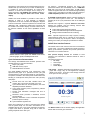
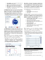
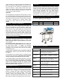
REFERENCE: _______________________ CUSTOMER: ________________________ 400HC-E & 500HC-E SERIES GRAVITY & VACUUM / GRAVITY STEAM STERILIZERS FOR HEALTHCARE APPLICATIONS PRODUCT SPECIFICATION PRODUCT Both the 400HC-E Series and 500HC-E Series Sterilizers consist of two models. The 422HC-E and 522HC-E Gravity Steam Sterilizers employ only gravity-downward displacement with positive pulse conditioning of loads. The 433HC-E and 533HC-E are combination vacuum / gravity steam sterilizers that employ either pressure/vacuum pulsing for dynamic air removal; or gravity-downward displacement with positive pulse conditioning. The gravity only sterilizer model is shipped with a total of 14 factory set cycles. The vacuum/gravity sterilizer model is shipped with a total of 24 factory cycles, which includes 2 test cycles. All cycles can be easily accessed in two easy steps. Custom cycle names can be designated for each processing cycle during installation. All cycle phases are sequenced and monitored by the control system, providing both audible and visual notification of deviation from key operating parameters. APPLICATION For general-purpose gravity or vacuum steam sterilization of hospital instruments and supplies. The selectable temperature range is from 230°F to 275°F (110°C to 135°C) and from 219°F to 275°F (104°C to 135°C) for liquid cycles. Applications include wrapped and unwrapped porous and nonporous single instrument or instrument trays up to 25 pounds; hard goods, gowns or towel packs; and liquids in self-venting or unsealed containers. The liquid exhaust is microcomputer controlled for linear and consistent liquid cool down, programmable within a specified range. MODEL SELECTION = Standard O = Optional CHAMBER DIMENSIONS 400HC-E Series: 4.6 Cu-Ft (130L) 17.5'' x 17.5'' (445 x 445 mm) x 26'' (660 mm) 422HC-E Gravity Displacement Model 433HC-E Prevacuum / Gravity Model 500HC-E Series: 9.7 Cu-Ft (275L) 21'' x 21'' (532 x 532 mm) x 38'' (965 mm) 522HC Gravity Displacement Model 533HC Prevacuum / Gravity Model DOOR SELECTION Manual Door O Power Door (400 Series Power DD - Special Order) SINGLE DOOR MOUNTING Recessed O Cabinet DOUBLE DOOR MOUNTING Recessed both ends (500 Series Only) O Cabinet, recessed one end CONTROL PANEL LOCATION On Unit O Wall Mounted, vertically – remote from unit ELECTRICAL SUPPLY - Sterilizer 115V, 1Ph 50/60 Hz O 230V, 1Ph 50/60 Hz VACUUM SOURCE & PIPING Ejector with copper/brass piping and valves O Ejector with stainless steel piping to chamber and jacket O Vacuum pump system with stainless steel piping to chamber and jacket. Requires 3-phase electric Note: Not available on units with integral boiler Not available on 400 Series with DD Select Vacuum Pump Voltage O 208V, 3Ph, 50/60 Hz O 230V, 3Ph, 50/60 Hz O 380V, 3Ph, 50/60 Hz O 480V, 3Ph, 50/60 Hz O 600V, 3Ph, 50/60 Hz STEAM SOURCE House Steam O 30 kW Steam Boiler with automatic feed water pump Note: Boiler not available on units with vacuum pump Boiler not available on 400 Series with DD 1 Select Steam Boiler Voltage O 208V, 3Ph, 50/60 Hz O 240V, 3Ph, 50/60 Hz O 480V, 3Ph, 50/60 Hz O 380/415V, 3Ph, 50Hz O 600V 3Ph 50/60 Hz Select Steam Boiler Material O Carbon Steel O 304L Stainless Steel Boiler for use with high purity water DISPLAY LANGUAGE (Select one) English O French O Spanish LOADING EQUIPMENT 400 Series interior rack with two extendable shelves 500 Series interior rack with two extendable shelves 500 Series chamber tracks for exterior load car 500 Series Load Car, Qty. ______________ 500 Series Smart Transfer Trolley, Qty. ____________ OTHER STERILIZER ACCESSORIES & OPTIONS O Automatic Steam Boiler Blowdown Control O ASME Blowdown Separator Tank O Water Saver Package for Vacuum Ejector Models only O 115V O 230V O 115V Water Chiller Unit for Water Saver O House chilled water COIL in lieu of electric Water Chiller O Uninterrupted Power Supply (UPS). Provides control power for up to 30 minutes to complete a cycle in process. (Vacuum ejector models only) O T-DOC Package for Instrument Traceability & Asset Management (including T-DOC Cycle) * O Getinge Online for remote connectivity to view real-time sterilizer process data * * Requires CAT-5 or 6 Ethernet cable to connect hospital’s network or existing internet connection to the machine’s NetCOM card. (Cabling is client’s responsibility – SEE ARRANGEMENT DRAWING) cETL Listed to CSA C22.2 Nos. 1010.1 and 1010.2.041 Seismic Anchoring Requirements per CBC 2010 Cycle Performance Validated to ANSI/AAMI ST8:2008 CSA 2314.7-03 (R2008) STANDARD SAFETY FEATURES • Steam interlock door switch – Prevents steam from entering the chamber when the door is not sealed. • Steam safety valve(s) – There are Steam Safety Relief valve(s) which ensures that the pressure in the chamber and or jacket do not over-pressurize. • Door obstruction shut-off – If the automatic door encounters an obstacle, a safety clutch stops the door movement and after a short time-out the motor is shut down. • Analog chamber gauges – Two needle-style gauges give real-time pressure readings in the chamber and jacket even in the event of micro-computer control system outage. • Parameter check – The control system verifies all userprogrammed cycle parameters against time / temperature sterility assurance level recommendations. A warning appears if user’s attempt to program a cycle beyond recommended parameters. • Supervisor password – A supervisor password is required to change cycle names or parameters. • Abort alert – Aborted cycles result in a warning message that requires user intervention before the chamber can be reopened. • Gasket retract valve – In the event emergency access to the chamber becomes necessary the gasket may be retracted manually. • Door safety baffle – In the unlikely event of a catastrophic door failure, gasket will blow out and a baffle at the chamber mouth directs steam away from areas where users might be working. • Heat guards and insulation – Insulation and heat guards are built in on all surfaces where users routinely come into contact, particularly near the door, and chamber openings. • Water alarm – The chamber drain is continuously monitored for the presence of water during a cycle. High water levels in the drain that cannot be corrected automatically result in an audible alert. CONTROL SYSTEM QUALITY STATEMENT Confidence in the Getinge Group is the most important quality criterion. This must be the hallmark of all our external and internal commitments, activities and products. Products and services supplied by Getinge must conform to the agreed terms and expectations to ensure recommendations for further business. The achievement of these quality goals is the basis for a continued competitive and successful enterprise. STANDARDS AND CODES The sterilizer shall comply with or meet the requirements of: ASME (Section VIII, Division 1) Code for Pressure Vessels Canadian Registration Number (CRN) Pressure Vessel Design Uniform Plumbing Code ETL Listed to UL 61010A-1 and UL61010A-2-041 ETL Listed to IEC 61010-1 and IEC 61010-2-040 Getinge Sterilizers employ the PACS 3500 modular PLC control system (CPU) to monitor and control all sterilizer operations and functions. The control system is factory programmed with standard sterilizing cycles. Each cycle is adjustable to meet specific reprocessing requirements. All user accessible control functions can be changed with appropriate password using the touch screen interface panel. The E-Series control panel consists of a user interface touch panel (called AVANTI), the CPU controller, a NetCOM communications card, a thermal printer, mechanical chamber and jacket pressure gauges, status indicators, and controls On/Off switch. A key lock is provided to insure all door power is disconnected when working in the chamber. Controls are located above the door for convenience. An internal deflection barrier routes steam vapor and moisture away from the door and behind the electronic controls to maintain temperatures at or below temperature limits. If 2 specified, the control panel can be located remotely from the sterilizer with up to 32.8 feet (10 m) of cable. An RS 232 port is provided for serial communications for central data collection or remote service analysis and is ready for TDOC® connection. The AVANTI user interface panel is a durable 8.4 inch diagonal SVGA color touch screen display. Audible and visual feedback is provided to users when a selection is made or a fault message is displayed. Temperature can be set, controlled and displayed in degrees Celsius or Fahrenheit. Pressure is preset to be controlled and displayed in PSI. Double door models have one printer and the AVANTI user interface display mounted at both ends of the pass-thru sterilizer for full control capabilities at either door. For backup / informational purposes, the same cycle performance data is also automatically sent to a USB flash drive port in the front of the control panel. A USB memory module is supplied with each unit and will hold approximately 10,000 cycles. This backup cycle data can be sent directly to a USB compatible printer in lieu of the USB flash drive. A NetCOM communications card is provided standard as part of the control system of each unit. The NetCOM is providing all of the cycle performance data to the USB port device. NetCOM also supports a separate Ethernet connection between the sterilizer and the following external data management systems (See Note): T-DOC data logging storage and printing T-DOC instrument tracking and asset management Getinge Online web based remote monitoring Note: Separate equipment and setup required, including network Ethernet cable drop by customer for each sterilizer. Internet accessibility may be required. Refer to arrangement drawing and contact your Getinge representative for details. AVANTI User Interface Features AVANTI USER INTERFACE FEATURES The AVANTI touch screen serves as the user’s command and control center. The screen is divided into specific sections to display cycle selection, operation and process performance information in a consistent manner. 400-500 E-Series control panel with AVANTI touch-screen; pressure gauges; printer; and USB port with cover. Cycle Performance Documentation The Getinge 400-500HC-E-Series sterilizer provides three standard means for cycle documentation: Paper cycle printer USB flash memory output NetCOM Ethernet connection The cycle printer documents cycle performance using special thermal paper for a permanent record (100 year storage warranty). Thermal printing allows for quiet operation. The printer is located in the control panel and documents the following on a 200-dpi dot matrix printer with 1.88" (47.6mm) wide paper: Process start time and date, sterilizer name and number, daily cycle number and total cycle count Cycle selected with time and temperature, with other adjustable parameters identified Cycle phase transition points, temperature, pressure and total cycle time Process fault information messages with time of occurrence Parameter Check provided a calculated, numeric process lethality Summary verification of time at selected temperature (min/max exposure values) Cycle verification signature line Paper roll is replaced by a “drop in and quick feed” method and the printed strips can be either accumulated on an automatic take-up reel, or torn off for individual cycle storage. A paper feed switch is provided, along with a switch for printing a duplicate of the “last cycle”. Four process display screens are available to show important cycle information in different formats for ease of recognition. The optional screens are: Bar Graph Circle Graph Plot Graph Details Display • Bar Graph – Displays temperature and pressure in a bar graph with a large, easy to read digital time remaining display in the center. Cycle time is the average of the last three cycles of each cycle type. 01:01:53 grv GRAVITY1 04 EXPOSURE P10 00:25:48 Chamber Temp 122.1 C Chamber PSIA 30.47 PSI 00:36 Remaining time P2 ) Cycles P1 Login Menu More Open Close Stop Start The Button Field across the bottom displays the application buttons that are used to give commands – 3 Cycle Select: Tap to access and select from 24 recommended factory cycles Login: Tap to access password protected features Menu: Tap to select operating screen displays Door controls: Use to open, close and seal doors Cycle Start: Turns green when conditions are OK to start a cycle. Tap to start cycle. The Status Field across the top of the touch screen identifies the selected cycle number, cycle name and current cycle phase on the left side. Cycle status and door status are displayed on the right side. Text alarm messages and noncritical system messages are displayed in the central area. • Circle Graph: Displays remaining time as a large easy to read graph that fills the circle as time elapses. Cycle time is the average of the last three cycles for each cycle type. 01:01:53 grv GRAVITY1 00:25:48 04 EXPOSURE P10 00:30:00 Exposure Time 121.1 C Exposure Temp 00:41 00:30:00 DryingTime P2 ) Cycles P1 Logout Menu More Open Stop User Access: The PACS control system is operated via an easy to use “menu system”. By default the user has access to the cycle selection, door control and cycle start. Users can run only validated cycles. Access to other areas such as running test cycles, re-setting parameters, calibration, service and maintenance is controlled by pre-defined password access. Refer to the MENU tree in the User Manual. Tap the MENU button to see the following sub-menus: System Menu Process Screen Documentation – Password Required Alarm History Supervisor Access: A start-up password is provided with the sterilizer for establishing first time password access for defined users / supervisors. Use the special “supervisor password’ to access and setup the following: (Refer to the MENU tree in Appendix C of the User Manual) Access the system “About” section to identify the model and software version number Add new users with passwords Adjust system menu for setting the calendar Select language, date format, and temperature and pressure measurement Re-order and/or re-name cycles Edit cycle parameters Activate utilities control feature to shut-off water and steam to the sterilizer to conserve energy Print the last cycle Start The Middle Field of the display screen shows actual, real time cycle information in the optional format selected. Cycle parameters such as exposure time, exposure temperature, or drying time are viewed and can be changed with the proper password clearance. Simply “tap” the value on the screen when in “standby” and follow the intuitive displays to input the new parameter value. Changes must be acknowledged and saved by the user. Note: Adjustment of time and temperature parameters requires user validation of the cycle efficacy. Factory recommended cycles are validated to ANSI/AAMI ST8. • Details Display: When the Details Screen is selected, the center area of the screen displays real time process data in text form. The remaining cycle time is displayed to the right of the text field. Note: Adjustment of time and temperature parameters requires user validation of the cycle efficacy. Factory recommended cycles are validated to ANSI/AAMI ST8. • Plot Graph. The start screen displays a plot graph of various process parameters. Each process parameter is displayed in contrasting colors. Additional process parameters are displayed in the status field. The remaining time is displayed to the right of the status field. FACTORY DEFAULT CYCLES MODELS 422HC and 522HC (14 total cycles) • 3 Gravity cycles of 30 minutes exposure at 250°F (121°C) with 45 minutes dry time. • 3 Gravity cycles of 10 minutes exposure at 275°F (135°C) with 45 minutes dry time. • 4 Gravity Immediate-Use* cycles for non-porous items – 3 4 minutes exposure at 275°F (135°C) with 30 seconds dry time. o 275°F (135°C) Gravity IUSS-3 Cycle* (4 total) – For sterilizing single unwrapped, non-porous instrument; or unwrapped non-porous instrument trays, up to 25 Lb. (11.3 kg) per tray. 275°F (135°C) sterilize temperature 3 minutes exposure 30 seconds dry time o 275°F (135°C) Gravity IUSS-10 Cycle* (2 total) – For sterilizing unwrapped porous or non-porous single instrument; or unwrapped porous or non-porous instrument trays, up to 25 Lb. (11.3 kg) per tray. 275°F (135°C) sterilize temperature 10 minutes exposure 30 seconds dry time • 2 Gravity Immediate-Use* cycles for porous and nonporous items – 10 minutes exposure at 275°F (135°C) with 30 seconds dry time. • 2 Liquid** cycles at 250°F (121°C); one with 30 minutes exposure; and one with 45 minutes exposure. Note: Adjustment of time and temperature parameters requires user validation of the cycle efficacy. Factory recommended cycles are validated to ANSI/AAMI ST8. * Steam sterilization by the unwrapped (IUSS) method is employed when immediacy does not permit the use of the preferable, wrapped sterilization procedure. Implantable devices should not be sterilized by the unwrapped method. ** Liquid cycles are not intended for sterilization of liquids used for direct patient contact. MODELS 433HC and 533HC (24 total cycles) o 275°F (135°C) Prevac-1 Cycle (3 total) – For sterilizing double wrapped instrument trays up to 25 Lb. (11.3 kg) per tray – or fabric packs. 275°F (135°C) sterilize temperature 3 minutes exposure 16 minutes dry time Note: Refer to AAMI ST79 guidance for Immediate-Use Steam Sterilization (IUSS). Sterilization by the unwrapped method (IUSS) with little or no dry time is efficacious when used in compliance with validated written instructions provided by the device manufacturers, the sterilization equipment manufacturer, the container manufacturer (if applicable) and when done in accordance with professional guidelines. Implantable devices should not be sterilized by the unwrapped method. o 250°F (121°C) Liquid1 Cycle** (1 total): For sterilizing liquids in vented or open 1000 mL (34 fluid oz.) or smaller containers. Important: Liquid cycles are not intended for sterilization of liquids used for direct patient contact. 250°F (121°C) sterilize temperature 30 minutes exposure Dry time: Not applicable 250°F (121°C) Liquid2 Cycle** (1 total): For sterilizing liquids in vented or open 1000 mL (34 fluid oz.) or smaller containers. Important: Liquid cycles are not intended for sterilization of liquids used for direct patient contact. 250°F (121°C) sterilize temperature 45 minutes exposure Dry time: Not applicable 273°F (134°C) Vac Bowie & Dick test cycle (1 total): For conducting B-D tests of prevacuum sterilizer using a validated test pack. 273°F (134°C) sterilize temperature 3 minutes & 30 seconds exposure zero minutes dry time o 275°F (135°C) Prevac-2 Cycle (2 total) – For sterilizing a single, wrapped instrument; wrapped instrument tray up to 25 Lb. per tray – or fabric packs. 275°F (135°C) sterilize temperature 3 minutes exposure 3 minutes dry time o o 275°F (135°C) Prevac-3 Cycle (1 total) – For sterilizing a single, unwrapped porous or non-porous instrument; or unwrapped porous and non-porous instruments in trays up to 25 Lb. per tray. 275°F (135°C) sterilize temperature 3 minutes exposure zero minutes dry time o 270°F (132°C) Prevac-4 Cycle (1 total) – For sterilizing double wrapped instrument trays up to 25 Lb. (11.3 kg) per tray – or fabric packs. 270°F (132°C) sterilize temperature 4 minutes exposure 16 minutes dry time o o o 270°F (132°C) Prevac-5 Cycle (1 total) – For sterilizing fabric packs. 270°F (132°C) sterilize temperature 4 minutes exposure 3 minutes dry time o 250°F (121°C) Gravity-1 Cycle (3 total) – For sterilizing double wrapped instrument trays up to 25 Lb. (11.3 kg) per tray – or fabric packs. 250°F (121°C) sterilize temperature 30 minutes exposure 45 minutes dry time o 275°F (135°C) Gravity-2 Cycle (3 total) – For sterilizing double wrapped instrument trays up to 25 Lb. (11.3 kg) per tray – or fabric packs. 275°F (135°C) sterilize temperature 10 minutes exposure 45 minutes dry time 268°F (131°C) Vacuum Leak Test (1 total): For testing the vacuum integrity of the sterilizer’s piping. Note: Vacuum leak test parameters are not adjustable. 268°F (131°C) sterilize temperature 3 minutes exposure 15 min dry time; 5 min equalize; 15 min test Note: Selection of time and temperatures other than factory recommendations require operator verification of the cycle efficacy. * Steam sterilization by the unwrapped (IUSS) method is employed when immediacy does not permit the use of the preferable, wrapped sterilization procedure. Implantable devices should NOT be sterilized by the unwrapped method. ** Liquid cycles are not intended for sterilization of liquids used in direct contact with patients. 5 CYCLE PROGRESSION • Gravity/Wrapped Goods (Pressure pulse conditioning) a. Conditioning—steam flows into the chamber for a timed period, followed by a series of positive pressure pulses to remove chamber air. b. Heat-Up—to selected temperature. c. Exposure—selected chamber temperature is attained and timed. d. Exhaust—chamber vented to atmospheric pressure. e. Dry—filtered air is drawn through chamber for the duration of time selected. (Either Gravity or Vacuum Dry is selectable; Vacuum Dry is recommended) f. Cycle Complete—signaled by a tone, light and display message on the Avanti touch screen. • Prevacuum/Wrapped Goods (Vacuum/pressure pulsing conditioning) a. Conditioning—steam flows into the chamber for a timed period, followed by a series of pressure/vacuum pulses to remove chamber air. b. Heat-Up—to selected temperature. c. Exposure—selected chamber temperature is attained and timed. d. Exhaust—chamber vented to below atmospheric pressure. e. Dry—a vacuum is created for the duration of the time selected. Filtered air is admitted at the end of the drying time, chamber to atmospheric pressure. f. Cycle Complete—signaled by a tone, light and display message on the Avanti touch screen. • Prevacuum/Unwrapped Goods (Vacuum/pressure pulsing conditioning) a. Conditioning—steam flows into the chamber for a timed period, followed by a series of pressure/vacuum pulses to remove chamber air. b. Heat-Up—to selected temperature. c. Exposure—selected chamber temperature is attained and timed. d. Exhaust—chamber vented to below atmospheric pressure. e. Dry—typically, not required for the unwrapped vacuum cycle. f. Cycle Complete—signaled by a tone, light and display message on the Avanti touch screen. • Gravity/Unwrapped Goods (3 minutes for nonporous items or 10 minutes for porous items) a. Conditioning—steam flows into chamber for a timed period to remove air. The 10-minute Flash cycle for porous items has a series of positive pulses for dynamic air removal. b. Heat-Up—to selected temperature. c. Exposure—selected chamber temperature is attained and timed. d. Exhaust—chamber vented to atmospheric pressure. e. Dry—filtered air is drawn through chamber for the duration of time selected. f. Cycle Complete—signaled by a tone, light and display message on the Avanti touch screen. • Liquids a. Conditioning—steam flows into chamber for a timed period to remove air. b. Heat-Up—to selected temperature. c. Exposure—selected chamber temperature is attained and timed. d. Exhaust—an adjustable linear exhaust. e. Cycle Complete—tone, light and display message signals. PERFORMANCE When installed and connected to specified utility services, the system provides accurate and repeatable performance. During the timed exposure phase, the temperature will be controlled by the chamber sensor at 1.44°F (0.8°C) above the set point (±0.1°C). Temperature selectivity is in 0.1°F (0.1°C) increments. Timing functions are selectable in one-second increments, and accuracy is within 0.04%. Temperature is controlled by a time proportioning continuous algorithm, called Proportional Integral (PI). A battery with a 10 year life holds programmed cycle values in memory. In the event of a power interruption, current cycle status is stored for up to 1 minute. CONSTRUCTION The chamber is constructed of an inner shell reinforced by a series of “U” channels that form the outer jacket of the chamber. The gasket ring and backhead (on single door models) are formed and welded to the chamber body. Chamber, door, and jacket material is constructed of 316L stainless steel. The interior chamber finish is polished to a high luster finish. All pressure vessel construction meets ASME code requirements for working pressures up to 45 psig (310 kPa). The gasket ring holds a continuous, one-piece silicone gasket, 0.63'' (16 mm) in diameter. The body assembly is thermally insulated with 1.5'' fiberglass insulation and is double thick between the jacket “U” channels. A steam baffle is provided to prevent condensation from wetting the load. An extra threaded opening permits passage of thermocouple leads to monitor interior and load temperatures. Steam connection to the chamber and jacket is 316L stainless steel material. A manual gasket retract valve is provided for emergency chamber access. When rack and shelves are supplied, shelf adjustments will be approximately every 2.5'' (63.5 mm). Individual rack supports and shelves are easy to remove for cleaning. VERTI-GLIDE DOOR The vertical sliding door is counterbalanced for ease of operation. When open, it is totally out of the way, allowing safe and complete access to the chamber. Opening or closing the manual door requires only gentle upward or downward hand pressure. The optional Power Door is operated by a foot switch, and the door will stop automatically if an obstruction is encountered. If the foot switch is actuated while the door is opening or closing, the direction will be reversed. The Power Door can be opened or closed manually. At the beginning of the cycle, steam pressure behind the gasket automatically seals the door and retracts automatically 6 at the end of the cycle. Sealing is positive and consistent. The gasket is recessed for added protection and long life. Once the cycle begins and the chamber is pressurized, the door cannot be opened. A safety switch prevents steam from entering the chamber when the door is not in the sealed position. The door is insulated with fiberglass insulation and covered with a stainless steel panel. PANELING The front paneling is constructed of nominal 0.050'' (1.27 mm) No. 3 brushed finished stainless steel and is hinged for easy access to components, the manual gasket retract valve and, if specified, the electric steam boiler. The trim panels are built-in to fit within a recessed wall or optional cabinet. When specified, the cabinet model will be made of the same material. WARRANTY A Getinge USA, Inc. warrants that each sterilizer is carefully tested and inspected and leaves the factory in proper working condition, free from visible defects. Sterilizers are warranted for one year from the start of the warranty, including parts and labor (excluding expendable parts). The ASME pressure vessel is further warranted to the original owner against structural failure for a period of 15 years from the date of initial operation. See warranty pamphlet for complete details. 500 SERIES FIXED HEIGHT TRANSFER TROLLEY For loading, unloading and transferring the 500 Series Load Car with and without tray sets or containers. Item No. 564710471 OPTIONAL – INTEGRAL STEAM BOILER Wt. 62 Lb. 28 Kg Size 58”L x 24”W x 38.5”H 1473 x 615 x 978 mm Max Load 286 Lb. 130 Kg The carbon steel or 304L stainless steel steam boiler will have a 30 kW capacity at standard 3-phase voltages, and include an automatic fill valve to ensure the correct water level at all times. Unit includes ASME CSD-1 low water cut-off safety device. The sterilizer control on/off switch controls the boiler control power (115V). The steam boiler is automatically controlled to generate and maintain a supply of steam to the sterilizer at minimum of 40 psig (3.72 Bar). An automatic feed water pump is provided as standard. CONSERVATION FEATURES The standard water ejector 400-500 series can be fitted with a Water-Saver and Water-Chiller package to reduce cold water consumption by 80% or greater depending on load and cycle conditions. The optional vacuum pump design will also reduce cold water consumption by approximately 80% when compared to the water ejector design. In addition, the two-stage mechanical vacuum pump is more effective during vacuum conditioning and will reduce total cycle time and steam consumption by 10%. A screen saver extends the life of the backlit LCD and saves energy. Touching any key illuminates and reactivates the display. The temperature of the discharge water is controlled by RTD to be less than 140°F (60°C). This device also conserves water by cooling the drain effluent only when needed. The Automatic Utilities Control feature provides a seven-day timer for programmed startup and shutdown of the sterilizer. When activated, this program shuts OFF water and steam valves to the sterilizer (including the optional steam boiler) to conserve energy. Cycles running beyond the programmed shutoff time will be completed. ENVIRONMENTAL IMPACT Getinge steam sterilizers are designed and constructed with our environment in mind. To aid in the conservation of natural resources, and in recognition of prevailing Environmental Policies, in particular ISO 14001, Getinge steam sterilizers are more than 90% (by weight) recyclable. Under normal operation, Getinge steam sterilizers produce no harmful byproducts. The Getinge steam sterilization process, in and of itself, produces nothing more dangerous than hot drain water. DOCUMENTATION / DRAWINGS Number Description 6013077801 400/500 Install / Arrangement Drawing, Brass Piping, Vacuum Ejector 6013009401 400/500 Install / Arrangement Drawing, Stainless Piping, Vac Ejector or Vac Pump PI0039 400/500 Piping & Instrumentation Diagram, Brass Piping with Vacuum Ejector PI0057 400/500 P&I Diagram, Stainless Piping with Vacuum Ejector P10058 400/500 P&I Diagram with Vacuum Pump OPA-0417-10 400 Series Seismic Anchorage OPA-1144-10 500 Series Seismic Anchorage HS3472 MP129 Water-Saver Arrangement Drawing HS4134 Electric Water-Chiller Drawing 7 provider of solutions for sterile processing in the healthcare sector. We aim to ensure the highest quality and safety at the lowest total cost. We offer complete solutions for a seamless work-flow, reducing the risk of contamination while helping healthcare to increase efficiency. Getinge USA, Inc. 1777 East Henrietta Road Rochester, New York 14623 USA Phone: 800.475.9040 Fax: 585.272.5033 Getinge Canada Ltd. 6685 Millcreek Drive, Unit 3 Mississauga, Ontario L5N 5M5 Canada Phone: 905.363.4150 GETINGE GROUP is a leading global provider of equipment and systems that contribute to quality enhancement and cost efficiency within healthcare and life sciences. We operate under the three brands of ArjoHuntleigh, GETINGE and MAQUET. ArjoHuntleigh focuses on patient handling and hygiene, disinfection, DVT prevention, medical beds, therapeutic surfaces and diagnostics. GETINGE provides solutions for infection control within Healthcare and contamination prevention within Life Sciences. MAQUET specializes in therapeutic applications, products, solutions and services for OR d ICU HC_ST_PS_400-500HCE_0413.1_EN_US © 2013 Getinge USA, Inc. Printed in U.S.A. ArjoHuntleigh, Getinge, and MAQUET are registered trademarks. We reserve the right to make changes to specifications and product information. Getinge Infection Control is the world leading