1
Institute for Energy Technology
OECD Halden Reactor Project
TUTORIAL
X Windows (UNIX) version
3.9
Graphical User Interface Management System
Institute for Energy Technology
OECD Halden Reactor Project
This document will be subjected to revisions in the future as the development of ProcSee continues.
New versions will be issued at new releases of the ProcSee system.
The information in this document is subject to change without notice and should not be construed as a commitment by Institute for Energy Technology.
Institute for Energy Technology, OECD Halden Reactor Project, assumes no responsibility for any errors that
may appear in this document.
Published by
: Institute for Energy Technology, OECD Halden Reactor Project
Date
: June 2014
Revision
: 3.9
PROCSEE
DOCUMENTATION
Table of Contents
Table of Contents .
1
1.1
1.2
1.3
1.4
1.5
1.6
2
. . . . . . . . . . . . . . . . . . . . . . . . . . . . . . i
Introduction .
. . . . . . . .
What is a Tutorial? . . . . . . . .
What to Expect from this Tutorial
Conventions . . . . . . . . . . . .
How to Use this Manual . . . . .
Definitions . . . . . . . . . . . .
Requirements . . . . . . . . . . .
.
.
.
.
.
.
.
.
.
.
.
.
.
.
.
.
.
.
.
.
.
.
.
.
.
.
.
.
.
.
.
.
.
.
.
.
.
.
.
.
.
.
.
.
.
.
.
.
.
.
.
.
.
.
.
.
.
.
.
.
.
.
.
.
.
.
.
.
.
.
.
.
.
.
.
.
.
.
.
.
.
.
.
.
.
.
.
.
.
.
.
.
.
.
.
.
.
.
.
.
.
.
.
.
.
.
.
.
.
.
.
.
.
.
.
.
.
.
.
.
.
.
.
.
.
.
.
.
.
.
.
.
.
.
.
.
.
.
.
.
.
.
.
.
.
.
.
.
.
.
.
.
.
.
3
3
4
5
5
5
6
2.1
Preparations . . . . . . . . . . . . . . . . . . . . . . . . . . . . . . . 7
Configuration of a ProcSee Environment. . . . . . . . . . . . . . . . . . . 7
3
Starting Up.
.
.
.
.
.
.
.
.
.
.
.
.
.
.
.
.
.
.
.
.
.
.
.
.
.
.
.
.
.
.
.
.
.
.
.
.
.
.
.
.
.
.
.
.
.
.
.
.
.
.
.
.
.
.
.
.
11
11
12
14
4.1
4.2
4.3
GED . . . . . . . . . . . . . . . . . . . . . . .
Creating a New Drawing . . . . . . . . . . . . .
Rectangle, circle, polygon, line/polyline and Text
Attributes . . . . . . . . . . . . . . . . . . . . .
.
.
.
.
.
.
.
.
.
.
.
.
.
.
.
.
.
.
.
.
.
.
.
.
.
.
.
.
.
.
.
.
.
.
.
.
.
.
.
.
.
.
.
.
.
.
.
.
.
.
.
.
17
17
20
22
5
Application Resources
3.1
3.2
3.3
4
5.1
5.2
5.3
5.4
5.5
6
6.1
6.2
6.3
. . . . . . . . . . . .
What to Start . . . . . . . . . . . . . .
How to Start the ProcSee System . . . .
Description of the Tutorial Application.
.
.
.
.
.
.
.
.
.
.
.
.
.
.
.
.
.
Database Definition . . . . . . . .
How to do this by means of GED.
Colours . . . . . . . . . . . . . .
Fonts. . . . . . . . . . . . . . . .
Patterns . . . . . . . . . . . . . .
.
.
.
.
.
.
.
.
.
.
.
.
.
.
.
.
.
.
.
.
.
.
.
.
.
.
.
.
.
.
.
.
.
.
.
.
.
.
.
.
.
.
.
.
.
.
.
.
.
.
.
.
.
.
.
.
.
.
.
.
.
.
.
.
.
.
.
.
.
.
.
.
.
.
.
.
.
.
.
.
.
.
.
.
.
.
.
.
.
.
.
.
.
.
.
.
.
.
.
.
.
.
.
.
.
.
.
.
.
.
.
.
.
.
.
.
.
.
.
.
.
.
.
.
.
.
25
25
25
27
28
30
Design of Classes . .
Making a New Library . . .
The Valve Class . . . . . . .
The Tank Class . . . . . . .
.
.
.
.
.
.
.
.
.
.
.
.
.
.
.
.
.
.
.
.
.
.
.
.
.
.
.
.
.
.
.
.
.
.
.
.
.
.
.
.
.
.
.
.
.
.
.
.
.
.
.
.
.
.
.
.
.
.
.
.
.
.
.
.
.
.
.
.
.
.
.
.
.
.
.
.
.
.
.
.
.
.
.
.
31
31
34
41
.
.
.
.
.
.
.
.
.
.
.
.
i
7
The Picture .
7.1
7.2
7.3
7.4
7.5
7.6
. . . . . . . . . . .
Database Definition . . . . . . . . . .
Instantiating . . . . . . . . . . . . . .
Setting Graphics Attributes . . . . . .
Setting Dynamic Graphics Attributes .
Creating a Window . . . . . . . . . .
Using Tdoc as Source . . . . . . . . .
.
.
.
.
.
.
.
.
.
.
.
.
.
.
.
.
.
.
.
.
.
.
.
.
.
.
.
.
.
.
.
.
.
.
.
.
.
.
.
.
.
.
.
.
.
.
.
.
.
.
.
.
.
.
.
.
.
.
.
.
.
.
.
.
.
.
.
.
.
.
.
.
.
.
.
.
.
.
.
.
.
.
.
.
.
.
.
.
.
.
.
.
.
.
.
.
.
.
.
.
.
.
.
.
.
.
.
.
.
.
.
.
.
.
.
.
.
.
.
.
.
.
.
.
.
.
.
.
.
.
.
.
.
45
45
46
48
48
49
51
8
The Simulator .
8.1
8.2
8.3
8.4
8.5
8.6
8.7
. . .
Task . . . . . . . . . . . .
Source . . . . . . . . . . .
Requirements . . . . . . .
Initializing the Application
Program Flow . . . . . . .
Compiling . . . . . . . . .
Testing Dynamics . . . . .
.
.
.
.
.
.
.
.
.
.
.
.
.
.
.
.
.
.
.
.
.
.
.
.
.
.
.
.
.
.
.
.
.
.
.
.
.
.
.
.
.
.
.
.
.
.
.
.
.
.
.
.
.
.
.
.
.
.
.
.
.
.
.
.
.
.
.
.
.
.
.
.
.
.
.
.
.
.
.
.
.
.
.
.
.
.
.
.
.
.
.
.
.
.
.
.
.
.
.
.
.
.
.
.
.
.
.
.
.
.
.
.
.
.
.
.
.
.
.
.
.
.
.
.
.
.
.
.
.
.
.
.
.
.
.
.
.
.
.
.
.
.
.
.
.
.
.
.
.
.
.
.
.
.
.
.
.
.
.
.
.
.
.
.
.
.
.
.
.
.
.
.
.
.
.
.
.
.
.
.
.
.
.
.
.
.
.
.
.
.
.
.
.
.
.
.
.
.
.
.
53
53
54
54
56
58
62
63
9
Historic Trend
9.1
9.2
9.3
.
Internal Trend Logger .
Trending Variables . .
Trend Curves . . . . .
.
.
.
.
.
.
.
.
.
.
.
.
.
.
.
.
.
.
.
.
.
.
.
.
.
.
.
.
.
.
.
.
.
.
.
.
.
.
.
.
.
.
.
.
.
.
.
.
.
.
.
.
.
.
.
.
.
.
.
.
.
.
.
.
.
.
.
.
.
.
.
.
.
.
.
.
.
.
.
.
.
.
.
.
.
.
.
.
.
.
.
.
.
.
.
.
.
.
.
.
65
65
66
69
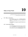
10
Make a Frame Work.
10.1
10.2
10.3
10.4
Make a start picture . . .
Use the librarie Buttons .
Extend the TutorPic . . .
Extend the program . . .
.
.
.
.
.
.
.
.
.
.
.
.
.
.
.
.
.
.
.
.
.
.
.
.
.
.
.
.
.
.
.
.
.
.
.
.
.
.
.
.
.
.
.
.
.
.
.
.
.
.
.
.
.
.
.
.
.
.
.
.
.
.
.
.
.
.
.
.
.
.
.
.
.
.
.
.
.
.
.
.
.
.
.
.
.
.
.
.
.
.
.
.
.
.
.
.
.
.
.
.
.
.
.
.
.
.
.
.
.
.
.
.
.
.
.
73
73
73
76
77
11
Further Enhancements .
11.1
11.2
11.3
11.4
11.5
11.6
11.7
11.8
11.9
11.10
11.11
11.12
11.13
. .
Picture update mode. . . . . . . . . .
Window title. . . . . . . . . . . . . .
Trend extensions . . . . . . . . . . .
Plot the picture . . . . . . . . . . . .
Run two RTM’s on the same Tutorial
Use a data configuration file . . . . .
Performance . . . . . . . . . . . . . .
More Process Units . . . . . . . . . .
Extend the Picture . . . . . . . . . . .
More Process Variables . . . . . . . .
Scales . . . . . . . . . . . . . . . . .
Functions . . . . . . . . . . . . . . .
Text Fields. . . . . . . . . . . . . . .
.
.
.
.
.
.
.
.
.
.
.
.
.
.
.
.
.
.
.
.
.
.
.
.
.
.
.
.
.
.
.
.
.
.
.
.
.
.
.
.
.
.
.
.
.
.
.
.
.
.
.
.
.
.
.
.
.
.
.
.
.
.
.
.
.
.
.
.
.
.
.
.
.
.
.
.
.
.
.
.
.
.
.
.
.
.
.
.
.
.
.
.
.
.
.
.
.
.
.
.
.
.
.
.
.
.
.
.
.
.
.
.
.
.
.
.
.
.
.
.
.
.
.
.
.
.
.
.
.
.
.
.
.
.
.
.
.
.
.
.
.
.
.
.
.
.
.
.
.
.
.
.
.
.
.
.
.
.
.
.
.
.
.
.
.
.
.
.
.
.
.
.
.
.
.
.
.
.
.
.
.
.
.
.
.
.
.
.
.
.
.
.
.
.
.
.
.
.
.
.
.
.
.
.
.
.
.
.
.
.
.
.
.
.
.
.
.
.
.
.
.
.
.
.
.
.
.
.
.
.
.
.
.
.
.
.
.
.
.
.
.
.
.
.
.
.
.
.
.
.
.
.
.
.
.
.
.
.
.
.
.
.
.
.
.
.
79
79
79
79
79
80
80
80
80
80
80
81
81
81
12
Summary
12.1
12.2
.
.
.
.
.
.
.
.
.
.
.
.
.
.
.
.
. . . . . . . . . . . . . . . . . . . . . . . . . . . . . . . . 83
What is Covered of the ProcSee System . . . . . . . . . . . . . . . . . . 83
Where to go From Here . . . . . . . . . . . . . . . . . . . . . . . . . . . 84
Index
ii
.
.
.
.
. . . . . . . . . . . . . . . . . . . . . . . . . . . . . . . . . . . . . . . . I
ProcSee Tutorial
1
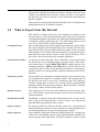
Introduction
This chapter is a general description of this tutorial with a presentation
of the contents and a description of the different conventions used in this
document.
1.1
What is a Tutorial?
Complete System
Description
A tutorial, in our case, is a compressed documentation of how to create
one or several complete applications using the ProcSee system. It is the
intention to give the beginner a hands on experience of ProcSee and
present terms and procedures to touch most of the different parts of the
system. The tutorial will simplify the introduction to the system and it
is recommended that the user works through it before retrieving more
detailed information from the “User’s guide” and the “Reference manual”.
The tutorial is based on generating pictures to be used for process control applications. Note that ProcSee can be used to generate user interfaces for any type of application.
essence
Tutorial
In most tutorials the goal is to work through one or more examples
based on prepared files delivered with the system. These files are used
to build a working application.
In addition to give a brief introduction to the system, it is also useful for
the user to test out other more complex functionality by appending functions to the already working example. Using the working example as a
template makes it efficient to test and debug added functionality.
ProcSee Tutorial
3
The tutorial is divided into different chapters dealing with each of the
modules and building blocks that the system consists of. The tutorial
can therefore be used as a reference to get information about different
ProcSee modules.
This tutorial is written on the assumption that the users are familiar with
using applications on X-Windows systems.
1.2
What to Expect from this Tutorial
This tutorial is dealing with most of the modules and utilities in the
ProcSee delivery. The tutorial application, that will be the end product
of working through this document, uses all the main building blocks for
creating the required application files. The following list gives a short
overview of what will be worked through in the tutorial:
creating directory
The second chapter starts with creating a tutorial directory where all the
files concerning this tutorial application will be located. Also the starting of the ProcSee system with the different modules will be described
in this chapter. You will also find the procedures for copying the predefined files delivered with the system to this specific directory. These
files will be used for start-up of the example application.
environment variables
A reference to where the binary files for ProcSee is located and a help
for the ProcSee system manoeuvring to the right resource files from a
user defined place, is called PROCSEE_DIR. In addition the two Environment variables, ARCH and PATH must be defined. The first one
is used by ProcSee to detect which machine architecture it is running on,
and the second is to avoid typing the complete path name to the executable files.
starting the system
The procedures for starting the complete ProcSee system requires only
two command line inputs in a terminal window. The start-up order of
the ProcSee processes is not fixed. Usually the Run-Time Manager
(RTM) is started first. A name server called Control is automatically
started by the RTM if not already running. When the RTM is running,
the Graphics Editor (GED) can be started.
default resources
This chapter gives an overview of the default resources (colours, fonts
etc.) in the ProcSee system and also the necessary tasks to be done for
initial preparation.
introduction to GED
Explanation of initial settings like background colour, world coordinates, snap etc.The drawing editor is used to draw a few objects and
then add different attributes to these objects.
design of classes
By using the GED two different ProcSee classes are constructed and
placed in a library for later use. The class library can be thought of as a
set of building blocks to be used to build pictures in GED.
design of picture
After finished creating the different building blocks like configuration
of the user’s environment, classes, and programming the simulator, the
process picture will be generated. The process picture consists of class
4
ProcSee Tutorial
instances, graphic primitives and application variables put together via
the editor. After having completed the process picture, the functionality
is tested by the editor test facilities.
the simulator
A small simulator program, coded in standard C, is running as a stand
alone process and is communicating with the RTM by use of standard
ProcSee Application Programmer’s Interface (API) functions. The task
of this simulator is to periodically update the RTM with the variables
that are used in the end picture.
running the application The application is expanded with a start-up window and picture, a library, and a database. It is now a complete ProcSee application.
1.3
Conventions
The following conventions are used in this manual:
• courier bold is used for constants such as .pctx
• $PROCSEE_DIR refers to the directory where ProcSee resides.
• <appName> means that appName is a user specified name.
• the information icon is used to highlight where more information
about a specific topic can be found.
• the explanation mark icon highlights important points in the text.
1.4
How to Use this Manual
This is a document supporting the ProcSee features and capabilities by
working through a complete application example based on a few system
files delivered with the system.
• Start with page number one and follow the descriptions.
• Avoid implementing new features to the tutorial example until
having finished the last page.
1.5
Definitions
application
See library, functions, windows, ....
attribute
An attribute is a variable local to the user interface, and does not have a
corresponding variable in a user program. See section 9.9 in ProcSee
User’s Guide.
callback functions
User supplied functions that will be called by the API to inform the application code about changes in the connection with ProcSee.
Introduction
5
class
A class is a reusable interface component. It is a picture, which may include attributes, functions, dialogues and graphic shapes, saved collectively as a class.
colour
A resource (see section 5.3 on page 27).
compile
Using the pcc program to generate a binary file from an ascii file.
font
A resource (see section 5.4 on page 28).
library
A container that can hold a number of graphic class definitions and resources.
pattern
A resource (see section 5.5 on page 30).
ProcSee connection
Mechanisms used to connect application code to the ProcSee RTM.
picture
The visible part of the user interface, displayed in windows.
resource
Colours, fonts and patterns, defined in a library or application.
toggle
Alternate between two states, e.g. on/off or open/closed.
update
Global update of picture in an application.
1.6
Requirements
Some prerequisites are required to be able to work through this tutorial.
Check the list below and find out if there is something that your system
is missing. Possible problems can be solved by your system administrator.
• The ProcSee system is properly installed according to the enclosed
installation specifications.
• Your system is running a version of UNIX, which is supported by
ProcSee.
• An editor for editing ascii files must be available
• Sufficient access privileges to the actual files and directories
referenced in the tutorial.
6
ProcSee Tutorial
2
Preparations
This chapter is dealing with a complete description of what is required
before starting the ProcSee system; setting the ProcSee variables
required, starting-up options, and copying the necessary files to a
specified directory.
2.1
Configuration of a ProcSee Environment
In a User Interface Management System (UIMS) like ProcSee, the user
need flexible possibilities to configure the system and interact with other systems according to his requirements.
The following subjects describe the preparation for starting a new and
empty application based on predefined colours, fonts, and other standard graphics resources.
Environment Variables
To make copying and system commands easier it is important to define
a unique ProcSee Environment variable in the operating system. This
variable is called PROCSEE_DIR, and is referred to in UNIX terms by
appending a $ in front of the variable.
The command for adding the PROCSEE_DIR to the Environment
variables (in a terminal window) is as follows:
ProcSee Tutorial
7
export PROCSEE_DIR=<full directory path to ProcSee>
(if using ksh1 or bash2)
or by using the command:
setenv PROCSEE_DIR <full directory path to ProcSee>
(if using csh3)
To verify if UNIX accepted the export command, a printout to the terminal window for the actual variable is generated by typing this on the
command line:
echo $PROCSEE_DIR
If the environment variable is set, an output to the terminal window will
appear showing the variable’s contents. To get a list of all the environment variables concerning the current user of the terminal window, type
env on the command line.
Another important variable used by ProcSee is the ARCH (architecture) variable. By using the env command, you will find out if the
ARCH variable is already defined. If not defined, it is done the same
way as the PROCSEE_DIR variable. This variable is used to identify
the type of computer you are using.
architecture name
Run the script:
$PROCSEE_DIR/script/p3setArch
to find your architecture name to be filled into the UNIX command:
export ARCH=<archName>
(if using ksh or bash)
or by using the command:
setenv ARCH <archName>
(if using csh)
The last environment variable to define is the PATH variable. This is a
standard environment variable containing different paths to frequently
used directories. It works this way; if a full path to a directory is specified in the PATH variable, all the files grouped under this directory is
accessible from anywhere in the file system without the actual path.
The syntax for including the directory where the ProcSee binary files reside, is as follows:
export PATH=$PROCSEE_DIR/bin/$ARCH:$PATH
(if using ksh or bash)
or by using the command:
set path = ($PROCSEE_DIR/bin/$ARCH $path)
1
ksh : korn-shell.
2
bash : born again shell.
3
csh : c-shell.
8
ProcSee Tutorial
(if using csh)
Copying Files
For convenience and separation of the different applications it is recommended to create a new directory for this tutorial. It is up to the user
where to create this directory.
If you don’t have a suitable directory already, create the new directory
in your $HOME (another standard UNIX environment variable) directory.
Preferably call the directory testTutorial.
The example below shows how to do this operation.
If you decide to use your own directory, skip the first UNIX command
and exchange the path argument to the cd command with your own
path.
mkdir $HOME/testTutorial
cd $HOME/testTutorial
The testTutorial directory will from this moment be the one referred to
without a path, because of the possible difference in the use of directory
above. A predefined application resource file is delivered to be used as
a basis for starting the ProcSee system (next chapter). This file reside in
the $PROCSEE_DIR/tutorial/$ARCH directory and is named Tutorial.pctx. Note that the file is dependent of the ARCH variable. Copy
this file to the testTutorial directory that was created as described
above.
cp $PROCSEE_DIR/tutorial/$ARCH/Tutorial.pctx <testTutorial path>/.
The testTutorial directory now contains the file Tutorial.pctx. Make
sure that you have write permission to the file. The $PROCSEE_DIR/
tutorial/$ARCH directory also contains the file Tutorial.Tdoc and a result directory. The result directory is supplied as an answer to the tutorial, and contains the key files. Later on in the tutorial you will be able
to look at the documented version of the Tutorial.pctx file, Tutorial.Tdoc, in a text editor. The file extension for a documented file is
.Tdoc.
It is also recommended that files like pictures, libraries and data bases
has their own directories. Go to the testTutorial directory.
Do: mkdir pictures, mkdir libraries and mkdir databases.
Preparations
9
10
ProcSee Tutorial
3
Starting Up
This chapter describes what to be started in the ProcSee system and
how it is done. The completed application picture will also be
presented.
3.1
What to Start
There are two main programs in the ProcSee system that must be running to be able to make a new application, their names are abbreviated
to:
•
RTM
Run-Time Manager
•
GED
Graphics Editor
When the system is installed, a system service called control is also installed.
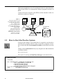
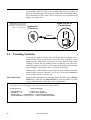
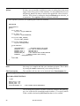
A graphics illustration of the connection between the two main programs and the control server in the ProcSee system is presented in Figure 1 on page 12.
GED is itself an application just as the Appl1 and Appl2 applications.
They are communicating through the Software Bus using the API library. To give some ideas about what such applications as Appl1 and
Appl2 could be, refer to Chapter 8 "The Simulator" on page 53, describing a simulator application.
The container next to the RTM is illustrating that the RTM is storing and
retrieving information about the user interface for the two applications
in a database file. In addition, a server program called Control is used to
set up the connection between the different programs, by holding the
connection information like which host a process is running on, and
ProcSee Tutorial
11
which port on that host to use. Even though Control is started automatically by the RTM, it is recomended to start the program in advance of
RTM.
Control will not be stopped by the RTM, and the intention is that it is
started once and never stopped.
Figure 1
The figure illustrates that
the Graphics Editor actually
is a ProcSee application.
The communication
between the applications
and the Run-Time Manager
is taken care of by the
Software Bus.
The UI Configuration
Database is where the
applications user interface
information reside. Control
should be started in
advance of the RTM..
Appl1
Appl2
API
API
SWBus
SWBus
Graphics
Editor
API
SWBus
UI Configuration
Database
Control
SWBus
Appl2
Run-Time
Manager
Graphics
Editor
Appl1
3.2
How to Start the ProcSee System
In the previous chapter it was stated that it is required to start the three
main ProcSee programs. Before trying to start these programs remember to define the three Environment variables as described in section
2.1.
Change to the testTutorial directory by using the unix cd command in
a terminal window.
cd <testTutorial path>
The syntax for starting the Run Time Manager is described below:
STARTING RTM
// unix shell
rtm -r Tutorial.pctx & 1 // Starting the executable file; rtm
// The -r option indicates a resource file
// Start the rtm from a directory
// where the .pctx file is present.
// An output on the terminal window will appear:
ProcSee Run-Time Manager(Release x.x --- )
<CR>
// Press Return on keyboard.
12
ProcSee Tutorial
The Graphics Editor started from the same terminal window as the
previous one. Remember appending the ampersand at the end of the
UNIX command if the programs should run in background.
STARTING GED
// unix shell
ged &
1
// Starting the executable file, ged, in background.
// An output on the terminal window will appear:
ProcSee GED (Release x.x ---)
<CR>
// Press Return on keyboard
In addition to RTM and GED, the Control program is automatically
started by the RTM. However, it is recomended to start the program in
advance of RTM. See the Reference Manual for more details on Control. After starting these two programs, the only window appearing on
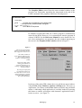
the screen is the Graphics Editor window shown in Figure 2.
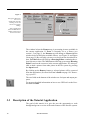
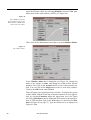
Figure 2
This is how the Graphics
Editor will look like the first
time it appears on the screen
The editor window is
separated into different pulldown menus, buttons,
windows, and input/output
fields.
This main editor offers
editing possibilities on
pictures and libraries by
starting a drawing editor in
another window.
By using the input field
second from bottom, the
user has direct access to the
function language, pTALK,
in the Run Time Manager.
The bottom field is for
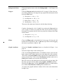
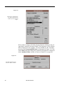
In the top of the main GED window there are pull-down menus indicated by the File, View, Windows, Options and Help menu. The text (e.g.
Application ::No Name) on the Focus: button just below the pull-down
menus, is indicating which application is currently loaded. By pressing
this button a window will appear with alternative applications and libraries to select. (see Figure 3)
Starting Up
13
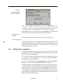
Figure 3
The figure illustrates
how a new
application already
running in the rtm
can be selected for
editing.
Select application
from the GED Focus
window and click on
the Focus button.
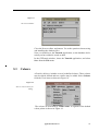
The window below the Pictures tag is presenting pictures available in
the current application. If Focus is currently set to a library (see
section 1.5 on page 5), the Pictures tag will change to Classes and the
window below will display available classes. (see Figure 23 and Figure
24 on page 32) By selecting a picture or a class from the described window, the Edit button will bring up a Drawing Editor containing the selected picture or class. The New button will bring up an empty Drawing
Editor based on the resources in the current application. It is also possible to load a picture from other places in the file system by pressing
the Open button.
By clicking on the Remove button, a selected picture will be removed
from the application. (See ProcSee User’s Guide on page 128 "Removing a picture".
The two fields at the bottom of the window are for input and output purposes.
To get more detailed information on how to use GED refer to the ProcSee User’s Guide.
3.3
Description of the Tutorial Application
The goal of this tutorial is to give the user the opportunity to work
through and get an overview of the main features of the ProcSee system.
14
ProcSee Tutorial
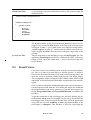
To start with the end product of this tutorial, a mimic picture will be produced presenting a part of a flow process with two valves and a tank
connected to each other with pipes. See Figure 4
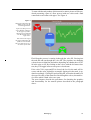
Figure 4
This figure illustrates the
mimic picture for the
tutorial application.
A part of a flow process
where fluid is coming in
to the upper left valve,
flowing into a tank and
out through the lower
right valve.
V1
The value at the top of
the tank is indicating the
fluid level in the tank.
The two characters T1 is
the name of the tank.
V2
Fluid from the process is coming in through the valve V1, flowing into
the tank T1 and out through the valve V2. The pipelines are changing
colours between light blue and white depending on whether there is fluid in the pipe or not. By clicking on the valves with the left mouse button, they will toggle between an open or closed state.
If the valve V1 is open and V2 is closed, the level in the tank will increase and the value (light blue rectangle) displayed in the tank, is updated accordingly. Closing V1 and opening V2, will make the tank level
decrease. Because of the same flow rate through the valves, the tank level will be stable if both valves are open.
The next chapters describe the procedures for obtaining the graphics
and functionality for the tutorial picture described in the paragraph
above.
Starting Up
15
16
ProcSee Tutorial
4
GED
This chapter will describe the most important functions in the Drawing
Editor and explain the design of some simple objects.
4.1
Creating a New Drawing
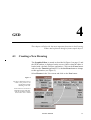
The Graphics Editor is started as described in Figure 2 on page 13 and
the GED window is displayed on the screen. Observe that the editor is
loaded with a default NoName application. Click on the Focus button
and select the Tutorial application. Use the Set Focus button to change
to this application. (see Figure 5)
Select Pictures in the View menu and click on the New button.
Figure 5
The figure illustrates how to
create a new picture in an
application already
runnning in the rtm.
Select Pictures in the View
Pull Down meny and then,
with the left mouse button,
click on the "New" button
ProcSee Tutorial
17
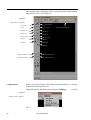
The drawing editor will appear on the screen and a picture named NoName will be created. (see Figure 6).
Figure 6
GED’s Drawing Editor
Test mode
Select Mode
Circle
Circle Arc
Dialogue Area
Ellipse
Ellipse Arc
Line/Polyline
Options PullDown Menu
Image
Rectangle
Polygon
Text
Instance
Trend
Keep
Graphic Attributes
Picture Properties
Selected Properties
Trend Properties
configurations
Before you start drawing, some editing options should be set, in order
to make the drawing more easy.
Chose the Options Pull Down menu and select Editing... .
Figure 7
Options menu - Editing ...
ure 7)
18
ProcSee Tutorial
(see Fig-
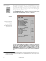
The Editing Options window will appear on the screen as shown in
Figure 8.
Figure 8
Editing Options
snap interval
The snap settings are done in order to make alignment of shapes more
easy.
In Snap Settings (World Coords), set both the X and Y snap to 10. Remember to activate the Toggle Buttons for X and Y. Click on the OK
button to confirm the settings.
Background Colour
Default value for background colour is black. If you want to change the
colour, do the following:
Chose the Options Pull Down menu and select Background... . The
Background window will appear on the screen. (Figure 9)
Figure 9
Options Pull Down menu
and the Background
Colours window
Chose a Colour from the Background colour menu or write the colour
name in the text input field. Confirm the text input by pressing the Ok
button.
GED
19
4.2
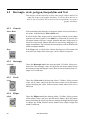
Rectangle, circle, polygon, line/polyline and Text
This chapter will describe how to draw some simple shapes and how to
equip the shapes with graphic attributes. It will also describe how to
draw a line or polyline, how to write a text string and how to connect
graphic attributes.
4.2.1
General
Select Mode
After terminating the drawing of a shape the editor will set itself into select mode, indicated by the Select Mode tool.
In select mode other shapes can be selected by clicking on the shape
with the left mouse button. If the Shift key (keyboard) is pressed, the
left mouse button will have a toggle function and more shapes may be
selected or unselected. Shapes may also be selected by dragging a rectangle around them. The currently selected shape(s) will be marked with
small rectangular handles.
Keep
4.2.2
If the Keep tool is selected, the chosen drawing tool will remain and
more than one shape of the same type, can be drawn in sequence
Rectangle
rectangle
4.2.3
Circle
circle
4.2.4
ellipse
20
Chose the Rectangle tool in the drawing editor’s Toolbar. Select position of the first rectangle corner and press the left mouse button. Keep
the button pressed and drag the cursor. Release mouse button when rectangle size is sufficient.
Chose the Circle tool in the drawing editor’s Toolbar. Select position
of the circle centre, and press the left mouse button. Keep the button
pressed and drag the cursor. Release mouse button when circle size is
sufficient.
Ellipse
Chose the Ellipse tool in the drawing editor’s Toolbar. Select position
of the ellipse centre, and press the left mouse button. Keep the button
pressed and drag the cursor, up-down to change the height and left-right
to change the width. Release mouse button when ellipse height and
width is sufficient.
ProcSee Tutorial
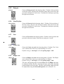
4.2.5
Polygon
polygon
4.2.6
Chose the Polygon tool in the drawing editor’s Toolbar. Select position
of the first corner, and press the left mouse button. Move the cursor and
press the left button for each corner. Terminate the drawing by pressing
the right mouse button
Line/Polyline
line/polyline
4.2.7
Text
text
4.2.8
Chose the Line tool in the drawing editor’s Toolbar. Select position of
the first corner, and press the left mouse button. Move the cursor and
press the left button for each corner. Terminate the drawing by pressing
the right mouse button
Chose the Text tool in the drawing editor’s Toolbar. Select position and
press the left mouse button. Write the text and press "return".
Circle Arc
circle Arc
Chose the Circle Arc tool in the drawing editor’s Toolbar. The Circle
Arc is drawn in the same way as the drawing of a Circle.
Default setting is: startAngle = 0 ° and openingAngle = 100°.
4.2.9
Ellipse Arc
ellipse Arc
Chose the Ellipse Arc tool in the drawing editor’s Toolbar. The Ellipse
Arc is drawn in the same way as the drawing of a Ellipse.
Default setting is: startAngle = 0 ° and openingAngle = 100°.
The start- and opening angle for both Circle Arc and Ellipse Arc may
be adjusted with the mouse by focusing the shape, pick up the adjusting
point and drag to desired value. The start- and opening Angle may also
be adjusted by using the Selected Properties. (see section 4.3.2)
GED
21
The Circle- and Ellipse Arc may be drawn either as Chord or Slice. The
selection is done in the Options Pull Down menu, as shown in Figure
10, before the arc is drawn..
Figure 10
This figure is showing
how to select between
Arc Chord and Arc Slice.
Arc Chord selected
4.3
Arc Slice selected
Attributes
This section will describe how to connect attributes to the shapes, lines
and text strings.
4.3.1
Graphic attributes
Graphic Attributes
When you draw a shape, you can decide position, form and size. If you
want to add attributes like colour, border, patterns etc., the Graphic Attributes is a tool for this purpose.
Select the shape you want to modify, and then click on the Graphic Attributes tool in the drawing editors Toolbar or click on the View menu
and select the Graphic Attributes... from the pulldown menu.
The Graphic Attributes window will pop up on the screen. (see Figure
11). The window includes attribute values for line and fill colours, patterns, line style, line width and fonts.
Figure 11
This figure presents the
Graphic Attributes
dialogue window.
To set a new attribute
value, select the actual
attribute and change it
in the presentation list
at the right side of the
window.
The attributes for shape colours are grouped in Line and Fill. Line/
Polyline and Text shapes, have no Fill attributes. Line/Polyline and
Shape Boarders, do have an extra attribute for Width, and for Line/
Polyline there is also an attribute for Style.
22
ProcSee Tutorial
If the selected Pattern = None, the Foreground and Background colours are not used. The colour of a Pattern is equal to the Background
colour selected.
Try to change the graphics attributes for some of the shapes, drawn in
section 4.2 on page 20. Select the shape by choosing Select Mode and
click on the shape. Chose from the different types of attributes.
Shapes with visibility = Invisible, will be invisible only when Test
mode is selected.
4.3.2
Selected Properties
Selected Properties
In addition to the attributes found in the Graphic Attributes window,
the Selected Properties window includes dynamic attributes for adjustment of height, width, positioning, rotation etc. of the shapes.
Select the shape you want to modify, and then click on the Selected
Properties tool in the drawing editors Toolbar.
The Selected Properties window will pop up on the screen. (see Figure
12) The window includes editing facilities for Attributes, Functions and
Dialogues.
Figure 12
This figure is illustrating the
Selected Properties window
for the selected shape.
Select the earlier drawn rectangle. In the Attributes, chose float height
and click on the Edit button.
The Attribute Editor window will pop up on the screen.
(see Figure 13 on page 24)
GED
23
Figure 13
This window shows the
Attribute Editor which is
used for changing the
selected attribute value.
Type the desired value for rectangle height (e.g. 109) and click on the
Compile button. If compilation is OK, a message: "Compiled OK" will
arrive in the Compile message: window. Then click on the Ok button
and the rectangle will have the new height.
4.3.3
Save and Document
save
In order to store the picture for later use, it has to be named and saved.
Save the picture with a new name by pressing the File menu and chose
the Save As... option. The Save As window appears on the screen. (see
Figure 14) Check that the directory is where you want to save the picture. Write the picture name in the Filename text field and click on the
Ok button, to save the picture.
Figure 14
Save As windowwith text
input fields.
document
24
Save the picture as an ascii file by pressing the File menu and chose the
Document option.
ProcSee Tutorial
Application Resources
5
This chapter gives an overview of the default resources (colours and
fonts) in the ProcSee system and necessary tasks for initial preparation.
5.1
Database Definition
In order to make it possible for the Graphics Editor (GED) and the Run
Time Manager (RTM) to operate without a program running, we declare the variables needed, in a database definition file, called Tutorial.pdat. This text file will be read by ProcSee at start-up and contains
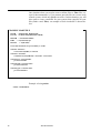
the following definitions:
DATABASE DEFINITION
// .pdat
float t1_level = 0.0;
int32 v1_state = 0;
int32 v2_state = 0;
5.2
How to do this by means of GED.
We want the process database script from Chapter 8 "The Simulator" on
page 53, to be included in our application. This is not strictly necessary,
since the tutorial program creates the variables anyway, but we want to
be able to edit our picture without starting this program1. For the appli-
ProcSee Tutorial
25
cation to read the database definition it has to be declared in the application resource file, the .pctx file that was originally copied from the
$PROCSEE_DIR/tutorial/$ARCH directory.
To do this from GED, select Processes under the Tutorial application in
the View Pull Down menu. Start the Process editor by pushing the Edit
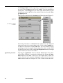
button in the Processes window. (se Figure 15)
Figure 15
How to select the Process
Editor from GED.
If the Tutorial process is not there, create it by pushing the New button
in the Processes window. In the New Process window, type the name
Tutorial for the name of the new process, and click on the Ok button.
(see Figure 16) The Process editor will then start.
Figure 16
New Process Name
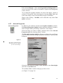
If the Tutorial.pdat file is already created, the content of the Process
Editor will be as shown in Figure 17. If you are going to create a new
.pdat file. the text as shown in Figure 17, has to be entered and the file
should be named: Tutorial.pdat.
1
26
The use of the terms "application", "process" and "program" might be a bit confusing. With "application" and
"process" we mean entities administered by the run-time manager. The "task", or the "program" is an external
piece of code running independently, communicating with ProcSee through the API.
ProcSee Tutorial
Figure 17
The Process Editor.
Close the Process editor, and answer Yes to the questions about saving
and installing the database files.
Now you should save the Tutorial Application, so the database declaration you have added is stored on disk.
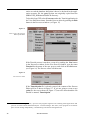
In the GED main window, chose the Tutorial application, and select
Save from the File menu.
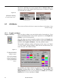
5.3
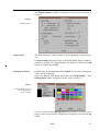
Colours
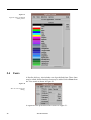
A ProcSee delivery, includes a set of predefined colours. These colours
may be edited, deleted and new colours may be added. Select Colours
from the View menu as shown in Figure 18.
Figure 18
How to select Colours for
editing.
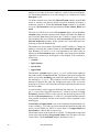
The colours are described by colour name. A segment of the default
colour palette is shown in Figure 19.
Application Resources
27
Figure 19
Segment of the predefined
colour palette
5.4
Fonts
A ProcSee delivery, also includes a set of predefined fonts. These fonts
may be edited, deleted and new fonts may be added. Select Fonts from
the View menu as shown in Figure 20.
Figure 20
How to select Fonts for
editing.
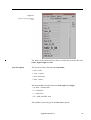
A segment of the predefined fonts is shown in Figure 21.
28
ProcSee Tutorial
Figure 21
Segment of the predefined
fonts
The name of the fonts has been chosen so that they describe the fontname, angle/weight and size.
font description
The first four letters describes the font name.
• aria = arial
• cour = courier
• helv =helvetica
• time = times
The intermediate item describes the font angle and weight.
• no item = normal font
• b = bold font
• i = italic font
• bi = bold and italic font
The numbers (last item) gives the font size in points.
Application Resources
29
If a font is not present on your system, the closest matching one will be
used.
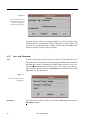
5.5
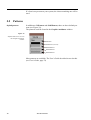
Patterns
default patterns
In addition to NoPattern and SolidPattern, there are three default patterns (see Figure 22).
The patterns could be found in the Graphic Attributes window.
Figure 22
Default Patterns as seen in
the Graphic Attributes
window
NoPattern
SolidPattern (selected)
DefaultPattern1
DefaultPattern2
DefaultPattern3
More patterns are available. The User’s Guide describes how to do this.
(see User’s Guide, page 79)
30
ProcSee Tutorial
6
Design of Classes
This chapter will deal with the design of classes as the high level
building blocks in the ProcSee system. The classes are saved into
libraries for later use when building the tutorial process picture.
6.1
Making a New Library
To create a new library in the Tutorial Application, select the File menu
in the main GED window and chose New and Library from the pulldown menu. (see Figure 23)
Figure 23
The figure illustrates how to
create a new library in an
application already
runnning in the rtm.
Select New and Library in
the File pull-down meny.
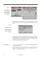
A new library, named NoNameLib will be created in the GED Focus
window. In the GED Focus window, select the NoNameLib and click
on the Set Focus button. The text in the Focus button will chang to: Focus: Library ::Tutorial.NoNameLib. (see Figure 24 on page 32)
ProcSee Tutorial
31
Figure 24
The GED Focus
window with the
library NoNameLib
and the GED main
window showing the
text in the Focus
button after clicking
on the Set Focus.
Save the library with a new name by pressing the File menu and chose
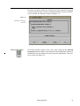
the Save As... option. This will bring up a new window as shown in Figure 25.
Figure 25
Window for saving a
library with a new name.
If not specifying the path,
the library file will be
placed in the directory
where the application is
located.
Click with the mouse pointer in the upper text input field and type TutorLib. Select the next field and type the current path using the UNIX
syntax: libraries. Click on the Ok button and verify that the message
appearing in GED’s output field is the same as:
Library TutorLib saved to libraries/TutorLib.plib
Drawing Editor
To create a new class in the library, bring up GED’s Drawing Editor by
pressing the New button.
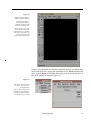
The drawing editor will appear on the screen as shown in Figure 26 on
page 33. The same drawing editor is used for designing both pictures
and classes, see Figure 6 on page 18.
32
ProcSee Tutorial
Figure 26
This is an illustration of
GED’s Drawing Editor.
The drawing editor is
currently presenting a
NoName drawing until
saved as something else.
At the top there are pulldown menus, and at the
left side there is a toolbar
for drawing facilities. At
the bottom there is an
input and an output field.
If a new class should be created at the application level, it could be done
in the following way: Select the application in the Focus window and
then, chose Classes in the View menu and click on the New button in
the GED window as shown in Figure 27.
Figure 27
The figure illustrates how
to create a new class in
an application.
Select Classes in the View
pull-down meny and then,
with the left mouse button,
click on the "New" button
Design of Classes
33
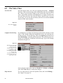
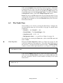
6.2
The Valve Class
save the class
Start the design of the valve class by renaming the default NoName
drawing. Click on the drawing editor’s File menu and select the Insert
As... option. Type the name: Valve, for the actual class in the Insert As
Class:. input field, and click on the Ok button. (see Figure 28) Note that
this will only insert the class into the library, and the class is not yet
saved to file. To save the class, the library have to be saved from the File
menu in GED’s main window
Figure 28
The Class Insert As
window
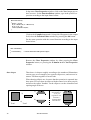
configure the drawing
It is mandatory to configure the drawing options before starting to work
with it. This include setting the background colour, the snap interval,
and the geometry for the drawing. Choose the Options menu and select
the Class Settings... from the pull-down menu. This will bring up a new
window for setting the coordinates of the drawing. Type in the settings
illustrated in Figure 29.
Figure 29
Window for setting the
geometry to the
current drawing.
World X and Y are the
coordinates of the
upper left corner of the
drawing area. The
origin in the
coordinate system will
represent the reference
point of the class,
After typing the right values into the World X, Y, Width, and Height,
click on the Ok button to confirm the changes.
Snap interval
34
To set a snap interval, chose the Options menu, and select Editing... .
(See Figure 8 on page 19.)
ProcSee Tutorial
Background Colour
Chose the Options menu, and select Background... . (See Figure 9 on
page 19.)
Polygon
Chose the Polygon tool as described in 4.2.5 on page 21. Place four corners of the polygon by referring to the x,y output in the information field
below the File menu:
1) first point: x = -40, y = -30
2) second point: x= -40, y = 30
3) third point: x = 40, y = -30
4) fourth point: x = 40, y = 30
Then press the right mouse button to end the shape drawing.
Line
Continue drawing the valve’s handle by pressing the Line tool (see
4.2.6 on page 21). Place two points the same way as with the polygon.
Remember to terminate the line after two points by clicking on the right
mouse button.
1) first point: x = 0, y = 0
2) second point: x = 0, y = -30
Ellipse
Chose the Ellipse tool as described in 4.2.4 on page 20. Press the left
button down in position x = 0, y = -40 and keep it down while dragging
the cursor to position x = 30, y = -30.
Graphic Attributes
Select the Graphic Attributes button, as described in Figure 11 on
page 22.
Select the ellipse shape in the drawing area.
Click on the Foreground attribute in the Line column, and select the
black colour in the colour palette list at the right side of the window.
Then click on the Line Width attribute and select the width number two
in the presented list. Click on the Line-Pattern attribute and set it to
Solid (pattern number two from the top of the list).
Move the cursor to the drawing area and select the polygon shape. Do
the same operation for this shape in the Graphic Attributes window.
Select the last line shape. Set the LineWidth attribute to width number
five, and the Line-Pattern to Solid (pattern number two).
To remove the graphic attribute window click on the same button that
brought it up.
Design of Classes
35
Class Properties
The graphics representation of the class is now defined and the next step
is to define some attributes and functions for the valve class. This is
done in the Class Properties window. Select the Class/Picture Properties button, or click on the View menu and select the Class Properties option from the pull-down menu.
The Class Properties window, illustrated in Figure 30, is used to create
new, edit, and delete an attribute, a function, or a dialogue.
Figure 30
This figure is illustrating
the Class Properties
window.
The window is used to
create new, edit, and
delete different properties
of the current class.
The first operation to do in this window is to create a new attribute for
the valve class. Click on the New button next to the Attributes: and type
in this pTALK1 statement (as shown in Figure 31 on page 37) in the Attribute Editor window and click on the Compile button to verify that
it compiled successfully (Compiled OK), before clicking on the Ok button
1
36
pTALK is the ProcSee programming language that has most of its syntax inspired from ANSI C, and can be
compiled and evaluated at run-time by the RTM. For more information about pTALK, refer to chapter 8 in the
ProcSee User’s Manual
ProcSee Tutorial
Figure 31
The Attribute Editor
window.
The statement is a declaration and initialization of the integer attribute.
Later on we will set the State attribute to a process variable.
Now, click on the New button, next to the Functions:. In the Function
Editor, type in the isOpen function, (as shown in Figure 32) click on
the Compile button. If the output field shows Compiled OK, click on the
OK button to exit the window.
Figure 32
The Class Properties
Function Editor window.
The next function to create, is for deciding the valve colour.
int ValveColour()
{
if( isOpen() )
return green;
else
return red;
}
A dialogue in a graphics user interface defines how the user interacts
with the system. To create a dialogue for the Valve class, click on the
New button, next to the Dialogues:.
Design of Classes
37
The Dialogue Editor window appearing, is separated into two input areas, one for the Trigger and one for the Action. Type the statement as
listed below, in the Trigger area or click (right mouse button) on the
Menu Button (at the right side of the window) and chose from the Trigger pop up menu.
Then type the statement in the Action input field as shown in Figure 33.
Figure 33
The Dialogue Editor
window.
The ChangeValveState is a function and is unknown for the rtm until
it has been made (it is the next thing to do). Click on the Compile button. Remove the window with the OK button. An error window will pop
up telling you that the compile failed, asking if the editor window shall
be closed, answer yes. Click on the Class Properties button (as brought
up the window) to remove the window.
Application function
38
Selecting the Application Tutorial and Set Focus button. The ChangeValveState function is creating by addressing the View and Functions and then select New. Later on we will explain how to make the
register function in the program. Putting the register function in an execute function makes the compile OK. This is done because the func-
ProcSee Tutorial
tion is not yet known in the rtm. It will first be known when the program
is connected to the rtm. For more information about execute see the Reference manual. the function is shown inFigure 34.
Figure 34
Window for making a
function.
Selected Properties
To define dynamic shapes in the valve class, bring up the Selected
Properties window either by pressing the Selected Properties button as
illustrated in the left margin or select it from the View menu. This window is shown in Figure 35
Design of Classes
39
Figure 35
This figure is illustrating
the Selected Properties
window for the selected
shape.
If the window is empty, select the polygon shape by clicking on the polygon shape with the left mouse button. The properties of the polygon
will be displayed in the window. Use the scrollbar for the Attributes:
and select the foregroundFillColour as illustrated in Figure 35. Click
on the Edit button and change the predefined assignment as displayed
in the Attribute Editor window as shown in Figure 36 on page 40.
Figure 36
The Selected Properties
Attribute Editor window
40
ProcSee Tutorial
Click on the Compile button and if the Compile messages: field shows
Compiled OK (see Figure 36), then click on the OK button to remove
the window. Do the same operation for the line and ellipse shapes, but
for the line shape select the foregroundColour. To remove the Selected Properties window, click on the Shape Properties button.
Insert the class in the File menu and close the drawing editor. If you
will close the main editor or load a new application before going on with
the Tank class, remember to save the TutorLib library first. Also do a
Document of the file.
6.3
The Tank Class
Start building a new class by pressing the New button. Configure the
new drawing the same way as in section 6.2 on page 34 with the listed
parameters:
• World X = -100, World Y = -100
• World Width = 750, World Height = 500
• Snap Interval X = 10, Y = 10
• Background colour... : ex. grey50 (see Figure 9 on page 19)
Save the tank by selecting the Insert As... option in the File menu and
name it Tank.
Class Properties
Bring up the Class Properties window, see Figure 30 on page 36, and
create two attributes for the tank class. Click on the New button next to
the Attributes:, and type the pTalk expression in the Attribute Editor
window as shown in the input frame below. (see Figure 31 on page 37)
float MaxLevel = 1000;
Click on the Compile button and if Compiled OK appears in the output
field, close the Attribute Editor window by pressing the Ok button. Do
the same operation with the second attribute according to the input
frame below.
float Level = 0;
Design of Classes
41
In the same Class Properties window, click on the New button next to
the Functions:. In the Function Editor window, type in the pTALK expression according to the input frame bellow:
float waterLevel()
{
float L = Level;
if( L > MaxLevel ) L = MaxLevel;
if( L < 0 ) L = 0;
return (L/MaxLevel)*91;
}
Click on the Compile button and if Compiled OK appears in the output
field, close the Function Editor window by pressing the Ok button.
Do the same operation with the second function according to the input
frame below:
char *instName()
{
return name();
}
// returns the name of the picture object
Remove the Class Properties window by either pressing the Class
Properties button, or pressing the X-button in the Class Properties
window.
draw shapes
Then draw six shapes roughly according to the numbered illustrations
on next page; two rectangles, two opposite ellipse arcs, and two text instances. Put them together to form a tank.
When drawing elliptic arcs, be aware that the operation is separated into
three parts. First you draw an ellipse with the wanted size, then you pick
and move the square "handles" on the ellipse to set the orientation and
opening angle of the arc.
1)
If the shapes,
from number 1
- 6, are put
together it will
look like a
partially filled
tank like this.
3)
2)
4)
5)
42
Text1
6)
Text2
ProcSee Tutorial
Text1
Text2
Graphic Attributes
Bring up the Graphic Attributes window, see Figure 11 on page 22,
and select the numbered shapes from 1 to 6.
1) Set Line-Pattern to None, and Fill-Foreground to colour medBlue.
2) Set Line-Pattern to None, and Fill-Foreground to colour
lightSkyBlue.
3) Set to same as 1).
4) Set to same as 1).
5) Set Line-Foreground to white, and Font to helv_b_14.
6) Set to same as 5).
Selected Properties
Bring up the Selected Properties window, see Figure 35 on page 40,
and select the numbered shapes from 1 to 6 over again. Edit the different
shape attributes to get a tank. Use float in front of all the attributes, except for theText and format that uses char*.
1) Edit to: X = 0; , Y = 50; , width = 100; ,
height = 90; .
2) Edit to: X = 2;
Y = ‘50 + 91 - waterLevel()‘;
width = 96;
height = ‘waterLevel()‘;
3) Edit to: X = 50; , Y = 50; , xRadius = 50; ,
yRadius = 37; , startAngle = 0; ,
openingAngle = 180;
4) Edit to: X = 50; , Y = 140; , xRadius = 50; ,
yRadius = 37; startAngle = 180; ,
openingAngle = 180;
5) Edit to: X = 27; , Y = 40; , theText = ‘Level‘; ,
format = “%6.1f”;
6) Edit to: X = 37; , Y = 165; ,
theText = ‘instName()‘; ,
format = “%s”;
Insert the drawing and leave the drawing editor.
Save and Document the library in the main editor’s File menu.
Design of Classes
43
44
ProcSee Tutorial
7
The Picture
In this chapter a picture is built, using the classes defined in Chapter 6
"Design of Classes" and the database definition, created in Chapter 8
"The Simulator".
7.1
Database Definition
The picture that we shall create, will show three process variables: The
tank and the two valves (see Figure 38 on page 47).
The three process variables will be created by the program created in
chapter 8 "The Simulator" on page 53 and made known to ProcSee
when the program is connected to the Run Time Manager (RTM). In order to make it possible for the Graphics Editor (GED) and RTM to operate without this program running, we also declare the variables in a
database definition script, called Tutorial.pdat. See Figure 17 on page
27. This script will be read by ProcSee at start-up and contains the following definitions.
DATABASE DEFINITION
// .pdat
float t1_level = 0.0;
int32 v1_state = 0;
int32 v2_state = 0;
ProcSee Tutorial
45
7.2
Instantiating
Now all the building blocks are ready and you can start building your
applications picture.
Select Pictures in the View menu in GED’s main window and proceed
as described in chapter 4 "GED" on page 17.
In the drawing editor, resize this window to a size that suits you before
you start drawing, and set the background colour to a pleasant value,
e.g. grey50. The background colour can be set from the Background...
option in the Options menu of the picture editor. You should also set
the X and Y snap to 10 from the Snap option in the Editing Options
window opened from the Options menu, all as described in Chapter 4
"GED".
The classes may be presented in either an Instantiate Class window or
in a Class Browser window. The selection is done in the Options pulldown menu. The Instantiate Class window will be used if Use ClassBrowser is not selected, see Figure 37. This selection must be done before the Instance tool is selected.
Figure 37
The Use
ClassBrowseroption in the
Options pull/down menu
and the Instantiate Class
window.
instances
Now you can start making instances of the Valve and Tank classes you
created in chapter 6 "Design of Classes" on page 31.
Select the Instance tool in the drawing editors Tools menu.
Class Browser
46
If Use ClassBrowser is selected, a browser with available libraries and
classes appears. First, select the library TutorLib,then select the class
Tank. Move the cursor to approximately the middle of the picture, e.g
coordinate (180, 110), and click on the left mouse button. An instance
of the tank will appear in the picture.
ProcSee Tutorial
Selected Properties
Select the Selected Properties from the property window buttons, located in the lower left corner of the drawing editor. The Selected Properties window appears. Select Rename in this window to give your
instance a name. Place the cursor in the empty text field in the appearing
dialogue box, and write the name T1.Then click on the Ok button.
Repeat the instantiating procedure for the valve class, creating a valve
instance. Place this valve somewhere over and to the left of the tank, e.g
coordinate (60, 70). Enter the shape property window once more, and
rename the instance V1.
Repeat this procedure, creating another valve in the lower right of the
picture, e.g coordinate (400, 340). Call it V2.
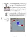
Line
Now connect the instances with a line. Select the Line tool in the Tools
menu. Draw a line from the V1 valve to the T1 tank by pressing the left
mouse button at the beginning, the corners, and the end points of the line
you need to create the pipe between the valve and the tank. Finish the
line by pressing the right mouse button. You can adjust the line afterwards with the handles if you are not satisfied with the coordinates. See
Figure 38. Draw a similar line from the tank T1 to the valve V2.
Figure 38
The picture. Two valves
and a tank, interconnected
with pipes.
The Picture
47
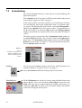
7.3
Setting Graphics Attributes
Select
Set the line width and colour from the Graphic Attributes window. Select the Select tool in the Tools menu. Then move the cursor to one of
the lines and select it. The line is now the currently selected object on
the screen and you can manipulate it through the graphic attributes window.
Graphic Attributes
The Graphic Attribute window, (see Figure 12 on page 23) pops up
when you select the Graphic Attributes button from the property buttons. Select LineWidth among the displayed attributes and pick a line
width in the list on the right side of the box, e.g number 9. Select a colour for the line in the same way. Select the second line in the picture,
and repeat the procedure.
Now you should have a picture looking approximately like the one in
Figure 38 on page 47.
7.4
Setting Dynamic Graphics Attributes
Now, connect the valve V1 to the process variable v1_state. Grab the
select tool once more and select the valve you named V1. To edit the
state attribute of the valve, you must open the Selected Properties window. In this window you will find a list of attributes. Select the attribute
"int State" and click on the Edit button. The attribute editor window
appears. Enter the window and set the value of the state attribute to the
dynamic expression ‘v1_state‘.
int State = ‘v1_state‘;
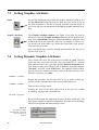
Repeat this procedure for the valve V2, or if you prefer a faster approach, use the command line of the picture editor and write:
V2.State = ‘v2_state‘
followed by a carriage return.
Connect the level of the tank (float Level) to the process variable
t1_level by writing in the command line:
T1.Level = ‘t1_level‘
Be careful to include the right kind of quotes in these statements. The
back quotes signifies a dynamic assignment. The tank level will change
whenever the quoted statement changes value.
Figure 39
The drawing editors
command line is situated
below the drawing
window.
48
ProcSee Tutorial
Test mode
Before you continue, test the dialogue of the valves. Set the editor in test
mode by selecting the Test Mode in the Tools menu. Place the cursor
on each of the valves and click with the left mouse button. The valves
should switch colours between green and red, signifying open and
closed.
Also test if the dynamics on the tank is working. In the drawing editors
command line write:
t1_level = 500.0
Then press Return. A light blue rectangle should now cover half of the
tank.
Let us add some more dynamics in the picture.
Chose the Select Mode and select the line connecting V1 and T1. Enter
the graphic attributes window. Select Line-Foreground. In the text edit
field at the bottom of the window, write:
V1.isOpen() ? lightSkyBlue : white
When typing is finished, press Return to insert this dynamic into the selected shape.
Select the line connecting T1 with V2. Repeat the procedure, but this
time write:
V1.isOpen() || T1.Level > 0 ? lightSkyBlue : white
Set the editor in Test Mode and test the new dynamics by opening and
closing the valves.
Save your picture. Select Save As... in the drawing editors File menu.
A standard file save window appears. Check that the directory is where
you want to save the picture, then: Write the name of the picture, TutorPic, in the filename text field, and click on the Save button, to save
the picture. (see Figure 14 on page 24)
7.5
Creating a Window
Your picture is now finished, but still you cannot access it from outside
of the graphics editor. To use the picture directly in your application, the
application needs a window of its own.
Use the Window editor in GED to create a window for your application.
The Picture
49
Open the Window editor by selecting Windows from the View pulldown menu in the main window of GED. (see Figure 40)
Figure 40
Select Windows from the
View pull-down menu in the
main window of GED. Then
click on the New button.
Then, click on the New button to the right, to open the Window Editor.
Figure 41
The window editor.
In the Window editor that is displayed (see Figure 41), change the
name of the window to win1, and change the width to 600, and the
height to 380. Click on the Accept button to set the values into the window. You can click on the Map button to have a look at the window.
Click on the OK button when finished.
This will supply your application with a window. To display the picture
in the window, add the following constructor function to your application, by selecting Functions under the Application level (see Figure
42). Select Functions from the View pull-down menu in the main window of GED and then click on the New button, as described for Windows in Figure 40 on page 50. Type the function text as displayed in
Figure 42, then:
50
ProcSee Tutorial
Figure 42
The Function Editor
window showing the
constructor function.
Click on the Compile and OK buttons and save the application to file.
To test the new window, leave the graphics editor (make sure you saved
your picture, library, and application), and shut down the RTM.
Stop the RTM wit a "kill". Read the process id (pid) of the RTM with
ps. Then stop it by writing kill followed by the process id.
ps -ef | grep rtm
kill <pid>
Restart the RTM from the command line of your shell writing:
rtm -r Tutorial.pctx
When the RTM starts up it will automatically load the application, open
the window and display your picture. Test out the functionality as you
did in section 7.4 "Setting Dynamic Graphics Attributes" on page 48, by
opening and closing the valves.
7.6
Using Tdoc as Source
The application and library and picture that we have created using GED,
could also have been created without GED, by using a text editor and
the ProcSee Code Compiler PCC.
PCC converts ProcSee.Tdoc files to binary files for applications, libraries, pictures, etc. The RTM produces .Tdoc files, when Document is
chosen from the menus in GED.
In order to document a picture, select the File menu and click on Document to create an ascii file (TutorPic.Tdoc) of the TutorPic.
At the moment not everything possible to do in the ProcSee system, is
possible to do from GED, like adding trend logger information. In these
cases you have to use a text editor to add these things to the system.
The sequence here are that you produce the .Tdoc file, use the text editor to change the .Tdoc file, then you run pcc on the file to create the
binary file that you read into the system with the Open menu options in
GED, or by restarting the RTM.
The Picture
51
One situation where you need to convert all the files to .Tdoc files, except for documentation, is if you want to store the files in a source code
control system, which only handles text files. In this situation, you will
also want to create a makefile for your system, that compiles all your
files (Both .c and .Tdoc). an example of such a makefile is shown below.
EXAMPLE MAKEFILE
IPATH = $(PROCSEE_DIR)/include
LPATH = $(PROCSEE_DIR)/lib/$(ARCH)
IXPATH = /usr/include/X11R5
LIBS = -L$(LPATH) -lp3
IFLAGS
= -I$(IPATH)
# Note that all actions are preceeded by a <TAB>
Tutorial: Tutorial.o
cc Tutorial.o $(LIBS) -o Tutorial
Tutorial.o: Tutorial.c
cc $(IFLAGS) -D$(ARCH) -c Tutorial.c -o Tutorial.o
Tutorial.pctx : Tutorial.Tdoc
pcc Tutorial.Tdoc
TutorLib.plib : TutorLib.Tdoc
pcc TutorLib.Tdoc
TutorPic.ppic : TutorPic.Tdoc
pcc TutorPic.Tdoc
Example of using make:
nmake -f MAKEFILE
52
ProcSee Tutorial
8
The Simulator
In this chapter we introduce a small program, coded in C, that interacts
with our user interface. The program is using the ProcSee Application
Programmer’s Interface (API) to update values of database variables.
8.1
Task
Imagine a process consisting of two valves with a tank in between connected by pipes. Water flows through the first valve into the tank and
out through the second valve.
We will make a small program that changes the level of the tank according to the state of the valves. If valve no. 1 is open, the level of the tank
should increase by a steady rate. If valve no. 2 is open, the level should
decrease accordingly.
The level of the tank is
calculated by the external
application according to the
state of the two valves. The
valves are controlled by an
operator .
RTM
Application
v1_state
Valve 1
API
Figure 43
Text1
t1_level
Valve 2
Text2
v2_state
ProcSee Tutorial
53
The program will communicate with ProcSee through three process
variables and a register function, expressing the state of the two valves
and the level of the tank.
8.2
Source
To create this program, a source file: Tutorial.c has to be created. If you
don’t want to do this now, all files for the tutorial can be found at
$PROCSEE_DIR/tutorial/$ARCH/result, and you can copy some of
the files you need from this directory.
You need to create a working directory under testTutorial, name it Tutorial, where you create the files: Tutorial.c and makefile. The content
of these files are described in section 8.3 - 8.6..
If you don’t want to type this yourself, just copy the files from
$PROCSEE_DIR/tutorial/$ARCH/result,
8.3
Requirements
The program, Tutorial.c, contains some definitions and variable declarations. Three functions that will be set up as callback functions (user
supplied functions that will be called by the API), and a main program.
In ProcSee’s Application Programmer’s Interface (API) a callback
function is used to update the actual variable from both the application
program and the RTM.
Constant definitions, type definitions, and function declarations required to use the API, are found in the api.h header file.
PROGRAM
/* c */
#include <stdio.h>
#include <time.h>
#include <api/api.h>
54
ProcSee Tutorial
In order to control the flow into and out of the tank, we define some constants representing the flow through the valves, and the maximum and
minimum allowed level of the tank
PROGRAM (continued)
/* The max and min levels of the tank */
#define MAX_LEVEL 1000.0
#define MIN_LEVEL 0.0
/* The flowrates of the valves */
#define V1_FLOWRATE 50
#define V2_FLOWRATE 50
We declare a Boolean variable to keep track of the ProcSee connection.
PROGRAM (continued)
static bool isConnected = 0;
For more information about the connection of the application code to
the RTM, see section 14.1 "A Small Example" in the ProcSee User’s
Guide.
The three essential variables of the application have an internal representation in the program.
PROGRAM (continued)
/* The application variables */
float t1_level = MAX_LEVEL;
int v1_state = 0;
int v2_state = 0;
In addition the variables have three identifiers used by the API when updating the ProcSee representation.
PROGRAM (continued)
/* Id’s for the variables */
int t1_id;
int v1_id;
int v2_id;
The Simulator
55
Three functions are called in different situations. A repetitive function
is called to change the water level continuously. Another function is
called when the program connects, the up() function, and a third is
called if the connection is broken, the down() function. In addition one
register function changeValveState() must be declared.
PROGRAM (continued)
int32 repeater( int32 ); /* This function is called repeatedly */
void up( int32, char* ); /* Functions called at connection events */
void down( int32, char* ); /* Functions called at connection events */
int changeValveState( int32, void* ); /* Register function */
8.4
Initializing the Application
The main routine of your program should initialize the application, set
up a process handler and start a main loop.
PROGRAM (continued)
int main()
{
To get contact with ProcSee, the API needs to know on which host to
find the communication server and the name of the ProcSee run-time
manager. In addition we have to identify our program with an application name and a process name.
The actual initialization of the API is done with the API function PfInitialize. Note that all the API functions have the prefix Pf. The Pf is an
abbreviation for ProcSee function.
PROGRAM (continued)
PfInitialize("Tutorial","Tutorial","rtm",NULL,100,1,&up,&down);
PfInitialize takes eight parameters:
applicationName
The name of the application. Our application is called "Tutorial". Several tasks can be running under the same application with different process names.
processName
The name of the process. Our process is called "Tutorial". Several tasks
can connect to ProcSee with the same application name, but the combination of application and process names must be unique. If NULL, the
name entered in applicationName is used.
56
ProcSee Tutorial
rtmName
The name of the ProcSee run-time manager. If NULL, the default name
of the RTM, which is "rtm", is used.
controlHostName
Name of the host where Control is running. If NULL, the environment
variable $CONTROLHOST is used.
cacheSize
Unused for the moment, use 0 as default value.
master
Unused for the moment, use 0 as default value.
up
The routine to be called when our task connects to ProcSee.
down
The routine to be called if the ProcSee connection is broken.
If something went wrong in the initialization routine, this will be registered in the apiError variable and can be displayed through PfPrintSystemError. The same procedure can be used after calling other API
functions.
PROGRAM (continued)
if (apiError != OK)
{
printf("Could not init API...\n");
PfPrintSystemError(apiError);
}
Note that PfInitialize doesn’t actually initialize the ProcSee run-time
manager. It initializes a routine that tries to get in touch with ProcSee.
When it succeeds the callback function registered in the up parameter
of PfInitialize is called. Your program’s initialization should be placed
in this function, not after the return from PfInitialize.
We want the program to update the process variables at a steady interval. We can accomplish this by using a "Process handler" - a function
called at regular intervals. We call our process handler "repeater" and
register it with PfSetProcessHandler.
PROGRAM (continued)
PfSetProcessHandler(&repeater, 1000);/*repeater called every 1000 ms*/
The function repeater should be called every second.
The Simulator
57
8.5
Program Flow
All preparations are finished and the program can enter its main loop.
All connection callbacks and process handlers will be executed in the
main loop.
PROGRAM (continued)
printf("Enter Pf loop\n");
if( PfMainLoop() != OK )
{
printf("Could not start Pf loop ...\n");
PfPrintSystemError(apiError);
}
The main loop is normally not terminated. If it terminates anyway, we
close our ProcSee connection and exits the program.
PROGRAM (continued)
}
if( PfClose() != OK )
{
printf("Could not close Pf ...\n");
PfPrintSystemError(apiError);
}
printf("Exit\n");
return 0;
/* End of main program */
When the program connects to ProcSee the connection callback "up", is
called. This is the natural place to create your process variables.
PROGRAM (continued)
void up( int32 status, char* msg )
{
This callback is called each time the ProcSee connection is established
or broken. The register function need two parameters.
PROGRAM (continued)
int32 numArgs = 1;
PfTArg args[] = { PfCUnsignedChar, 0 };
58
ProcSee Tutorial
To know whether to create the variables or not, we check the status parameter.
PROGRAM (continued)
if ( status & PfCrtmResume )
{
printf("Connection re-established \n");
return;
}
printf("Connection established \n");
If the PfCrtmResume bit is set, this routine has already been executed
and ProcSee remembers it. If not we go on creating PfRegisterFunction.
PROGRAM (continued)
PfRegisterFunction( "changeValveState_f", changeValveState, numargs,
if(apiError != OK)
printf("Failed to create changeValveState.\n");
args );
The parameters in the PfRegisterFunction is the name of the function,
the function itself, the number of arguments and the argument description. the changeValveState function have one argument, the name
of the variable to be toggle.Continue to create the variables.
PROGRAM (continued)
v1_id = PfCreateVar("v1_state", PfCInt, NULL, 1, &v1_state);
if(apiError == OK)
printf("variable v1_state added \n");
We create our variables with a name, a type, a Record type name, a
cache fix parameter (unused) and a value pointer.The variable name is
identical to the one we use in the definition of our picture and in the database definition script. We have chosen integer as a representation for
the state of the valves in our picture. In this context, the integer is defined PfCInt. Since the type is not a record, you should enter NULL for
the record type name.
The Simulator
59
In the last parameter we enter the address to the internal representation
of the variable. If the variable is changed in one of the pictures it will be
reflected in this variable.
PROGRAM (continued)
v2_id = PfCreateVar("v2_state", PfCInt, NULL, 1, &v2_state);
if(apiError == OK)
printf("variable v2_state added\n");
t1_id = PfCreateVar("t1_level", PfCFloat, NULL, 1, &t1_level);
if(apiError == OK)
printf("variable t1_level added\n");
We add two more variables representing the state of a second valve and
the level of a tank. The tank level is represented as a float; PfCFloat.
In order to increase speed when creating variables, the function PfCreateVar is storing the variable information in a local buffer, and relies
on the user to call the API function PfFlushCreateVar when variable
creation is finished. When PfFlushCreateVar is called, all the buffered
variables are created in the RTM at once. Before leaving the connection
callback, a flag is set to remember that the ProcSee connection is working.
PROGRAM (continued)
PfFlushCreateVar();
isConnected = 1;
}
/* End up */
If the ProcSee connection is broken the callback function "down" will
be called. In this function you don’t have to do much. Just print a message and reset the flag.
PROGRAM (continued)
void down( int32 status, char* msg )
{
printf( "Lost contact with ProcSee (‘%s‘)\n", msg );
isConnected = 0;
}
60
/* End down */
ProcSee Tutorial
Every second the repeater function will be called
PROGRAM (continued)
int32 repeater( int i ) /* This function is called repeatedly */
{
Here we check the state of valve number 1. If the valve is open the level
PROGRAM (continued)
if ( v1_state != 0 )
/* Valve V1 is open */
t1_level += V1_FLOWRATE;
in the tank should increase according to the flowrate of the valve.
If valve number 2 is open the level of the tank should decrease according to the flowrate of this valve.
PROGRAM (continued)
if ( v2_state != 0 )
/* Valve V2 is open */
t1_level -= V2_FLOWRATE;
Before updating the ProcSee variable, we check the tank level against
the limits. At this point it could be appropriate to execute some kind of
alarm action, but we are satisfied with just stopping the tank level from
increasing / decreasing.
PROGRAM (continued)
if ( t1_level < MIN_LEVEL ) /* Tank is empty */
t1_level = MIN_LEVEL;
if ( t1_level > MAX_LEVEL ) /* Tank is full */
t1_level = MAX_LEVEL;
Finally we tell ProcSee about the change of the value. We use the flag
from the connection callbacks to determine if the ProcSee connection is
working. If the connection is ok, the value is put into the send buffer
with the function PfSend.
The Simulator
61
PfSend uses the id of the variable, that was returned by PfCreateVar
in the up function. When all the values has been put into the send buffer,
the buffer is transmitted to the rtm with the PfFlush function.
PROGRAM (continued)
if ( isConnected )
{
PfSend( t1_id ); /* Make the changes known to ProcSee */
PfSend( v1_id );
PfSend( v2_id );
PfFlush();
}
return OK;
/* End of repeater */
}
The function changeValveState will be called every time one of the
valve is clicked on with the left mouse button.
PROGRAM (continued)
int changeValveState( int32 numArgs, void* data )
{
int32 size, type, id;
void *theData;
int *value;
if( numArgs != 1 )
return !OK;
theData = PfGetFuncArg( &data, &type, &size );
if( type != PfCUnsignedChar || size > 64 )
return !OK;
id = PfId( PfLocalProcess, (char*)theData );
if( apiError == OK )
{
value = (int*) PfData( id );
*value = !*value;
}
return OK;
}
/* End of changeValveState */
This function toggle the state of the two valves in the process picture.
8.6
Compiling
The statements necessary to compile your program can be found in
$PROCSEE_DIR/tutorial/$ARCH/result/makefile. Please note that
this makefile is architecture dependent, you should copy it from the preferred architecture catalogue to your working directory.
62
ProcSee Tutorial
The example below shows examples of the sun4solaris2, hprischpux9
and sgi makefile. Also note that all actions must start with a <TAB>.
MAKEFILE
IPATH = $(PROCSEE_DIR)/include
LPATH = $(PPROCSEE_DIR)/lib/$(ARCH)
# These variables are architecture dependent :
# hprischpux9 :
# IXPATH = /usr/include/X11R5
# LIBS = -L$(LPATH) -lp3
# sun4solaris2 :
# IXPATH = /usr/openwin/include/
# LIBS = -L$(LPATH) -lp3 -lgen -lsocket -lnsl -ldl
# sgi :
# IXPATH = /usr/include/X11
# LIBS = -L$(LPATH) -lp3
IFLAGS
= -I$(IPATH) -I$(IXPATH)
# Note that all actions are preceeded by a <TAB>
Tutorial: Tutorial.o
cc Tutorial.o $(LIBS) -o Tutorial
-chmod 775 Tutorial
Tutorial.o: Tutorial.c
cc $(IFLAGS) -D$(ARCH) -c Tutorial.c -o Tutorial.o
When the makefile and the source file are ready, compile the file by running make from your command prompt.
For more information on compiling and linking, see "Part 3 - Manual
Pages - Application Programmers Interface Manual pages - Compiling
and Linking" in the ProcSee Reference Manual.
8.7
Testing Dynamics
Start the program you wrote in chapter 8 "The Simulator" on page 53.
At your shells command line, write the program name:
Tutorial
If the program is working correctly it will reply with the following messages in the terminal window:
Enter Pf loop
variable v1_state added
variable t1_level added
The Simulator
63
variable v2_state added
If you are loading the picture in GED, set the editor in test mode.
Open valve V1. Close valve V2. Watch the level of tank T1 increase.
Close valve V1. The tank level stops increasing.
Open valve V2. Watch the level of tank T1 decrease.
Open valve V2. The level of tank T1 stabilizes.
64
ProcSee Tutorial
9
Historic Trend
The aim of this chapter is to give a brief description of the ProcSee trend
logging system. Historical data can be displayed as curves in trend
diagrams, referred to as Trend Display. Trend logging in our terms
means the process of collecting and administrating data.
9.1
Internal Trend Logger
Many applications need to store and display historical data. The number
of variables to be trended vary a lot. Thus the design of the ProcSee
trend logger had to be as flexible as possible to meet a wide range of requirements.
ProcSee Tutorial
65
In our tutorial, there are only a few variables that are to be trended. In
this case, the trend logger can easily run within the RTM without affecting performance of the system. This is referred to as an internal trend
logger. (see Figure 44)
Figure 44 The application
developed in this tutorial is
connected to an internal trend
logger in Tutorial.pctx.
Trend Log RTM
(Tutorial.pctx)
Application
(Tutorial.c)
logged
PfFlush()
9.2
data
Trending Variables
Let us say we want to see how the level of the tank is changing over a
period of time. The way this is done in ProcSee is by setting up a trend
logging system. This system consists of two parts. Part one says which
variables to trend, the log medium (disk or memory), how often they
should be logged etc. Part two is concerned with the physical presentation or display of the historic data, e.g. colour of the curve.
Unfortunately, GED cannot be used to specify how variables should be
trended in this version of ProcSee. So we have to use the combination
of a text editor and pcc to do the job.
Edit Tutorial.Tdoc
Document the application, by using the menus in GED, to get a Tutorial.Tdoc file. Open the file Tutorial.Tdoc in your text editor. Try adding the following lines within the scope of application:
Declaration of a trend logger which is internal to the display RTM
trendLog myLog
// name of the logger
{
timeTickIntvl= 1;
// ‘ticked’ every second
timeMaster = 2;
// ‘ticks’ sent by application
timeVariable = “myGlobalTime”; // variable for time stamping
trendVariableFile = “myVars.ptrv”; // where to find trend variables
}
66
ProcSee Tutorial
This declaration says that we will have a trend logger that is named myLog and it will be ticked every second. The timeMaster variable has a
value of 2, this indicates that an external application is responsible for
ticking the trend logger at the specified interval. In our case this application is the simulator we have written.
The trend logger must have a notion of time. Here this is done by letting
the application set and advance time by changing the value of a process
variable named myGlobalTime.
Save Tutorial.Tdoc
Further on, we want to declare the trend variables in a separate file. The
reason for keeping them separate, is that the number of trend variables
tend to be very large in most trend logging systems.
pcc Tutorial.Tdoc
After adding the lines described in on page 66, save the file and run it
through pcc to get a new Tutorial.pctx file. This file will have to be
loaded into the RTM for the trend logger to start.
Edit Tutorial.c
The next step is to add the myGlobalTime variable to the simulator program. Add the time variable as described below:
Add variable to the simulator program
PROGRAM
/* The application variables */
float t1_level = MAX_LEVEL;
int v1_state = 0;
int v2_state = 0;
int
myGlobalTime = 0;
// telling trend logger current time
/* Id’s for the variables */
int t1_id;
int v1_id;
int v2_id;
int time_id;
// id for time added
The variable must then be created:
Creating the time variable in the API
PROGRAM
myGlobalTime = time(NULL);
time_id = PfCreateVar("myGlobalTime", PfCInt, NULL, 1, &myGlobalTime);
if(apiError == OK)
printf("variable myGlobalTime added\n");
Historic Trend
67
PfSend
We have now created the variables necessary to setting time in the trend
logger. In the first version of the simulator, we only updated the level of
the tank, t1_level. This time we also need to update the value of myGlobalTime. This is done by calling the function PfSend again with time_id
as parameter. The repeater function will now look like:
The repeater() function now updating more than one variable
PROGRAM
int32 repeater(i)
int32 i;
{
if ( v1_state != 0 )
t1_level += V1_FLOWRATE;
if ( v2_state != 0 )
t1_level -= V2_FLOWRATE;
if ( t1_level < MIN_LEVEL )
t1_level = MIN_LEVEL;
if ( t1_level > MAX_LEVEL )
t1_level = MAX_LEVEL;
if ( isConnected )
{
myGlobalTime++;
// increment time by one second
PfSend( t1_id );
// new value for tank level in RTM
PfSend( v1_id );
// the state of V1
PfSend( v2_id );
// the state of V2
PfSend( time_id );
// new value for time variable in RTM
PfFlush();
// update variables, tick trend log
// and update screen
}
return OK;
}
make
Next step is to compile and link your simulator program. This is done
by issuing the make command at your working directory.
Edit Tutorial.pdat
The variables will also have to be declared in the Tutorial.pdat file:
Showing the Tutorial.pdat file
DATABASE DEFINITION
// .pdat
float t1_level = 0.0;
int32 v1_state = 0;
int32 v2_state = 0;
int myGlobalTime = 5;
// time variable must be defined here
The last thing that remains to be done in order to configure the trend logger, is to create the file containing trend variables, i.e. to specify which
of the variables declared by PfCreateVar that is to be trended.
68
ProcSee Tutorial
Edit myVars.Tdoc
Create and open a new file called myVars.Tdoc. The content of this file
should look like:
Trend variable configuration file
trendVarConfig myVars
{
trendVar t1_level
{
lCycle=1;
hist=10800;
type=5;
lo=-9999999;
hi=9999999;
}
}
The lCycle attribute of the trend variable t1_level says that it is to be
logged every second.The hist attribute is the time span of which values
are logged. (10800 / 1 gives 10800 values to be logged in a ring buffer).
Attribute type has a value of 5, which means the actual value of the variable is logged. lo and hi reflects the lower and upper range of the trended value.
pcc myVars.Tdoc
9.3
This file must now be run through pcc to get the myVars.ptrv file. The
application Tutorial.pctx can now be reloaded from GED. Left mouse
button on File, Open and Application..., select Tutorial.pctx and click
on OK button.
Trend Curves
Up to now we have been looking at how to define an internal trend logger. Now it is time to present data in a ProcSee picture. To define a
trend, select the trend tool in the Tools menu in the Drawing editor, and
move the cursor to position (300,40) and press the left mouse button.
The trend graphic shape will appear in the window with a default width
and height. As default one time label shape is placed above the trend diagram.
Now it’s time to change the width and height of the trend. Select the Selected Properties menu from the Tools menu and choose the width and
the height attributes and set the geometry to 300 and 200 respectively.
Set the foregroundColour and foregroundFillColour to medBlue and
steelBlue.
To get the connection to the trend logger we just have defined, the default attribute trLog in the Trend shape is set to myLog. Recall that this
trend logger name is the one specified in the Tdoc file in the application
scope with the keyword trendLog. Another important attribute in the
trend shape is timespan. This attribute is used for specifying the
Historic Trend
69
number of seconds of the curve which is visible in the trend diagram.
As default this attribute is set to 240, change it to 5 minutes by setting
timespan to 300.
To define a trend curve select the Selected Trend window in the Tools
menu. A window will appear which is used for defining all shapes a
trend may consist of. From this Selected Trend window it is possible
to create a Presentation (trend presentation), Time Labels, Ruler and
Grid.
The first we will do is to create a Presentation shape. Select the Presentation button from the options menu which will enable the New button. Press this New button and select the TrendPres1 shape in the list.
The attributes that are available for the Presentation will appear in the
Selected Properties window. If this window isn’t open then open it by
choosing it from the Tools menu.
The trend curve just created is by default called TrendPres1. Change its
name by selecting the rename button in the Selected Properties window. Rename it to myCurve. It is very important to set some of the attributes in the Presentation shape to another value than system default,
otherwise no trend curve will appear on the display. The essential attributes are:
• variable
• logFrequency
• lowerLimit
• upperLimit
The attribute variable must be set to "t1_level" which where added to
the trend variable file myVars.Tdoc. The name of the trend variable file
where set up in the trendLog part within the application scope. Change
the attribute to "t1_level". This variable is used as an indication of the
amount of liquid in the tank. By changing the state of the valves the
trend curve myCurve will reflect the amount of liquid in the tank for the
last 300 seconds.
A trend variable can be logged at different time intervals. As an example, t1_level can be logged at intervals of 1, 5 and 10 seconds. The logFrequency attribute can be used to specify the desired log interval for
the current Presentation shape. A value of -1 (default) indicates that the
best possible resolution for this trend variable will be supplied by the
trend logger.
lowerLimit and upperLimit is set to the minimum and maximum value the variable t1_level may get. In our tutorial the liquid in the tank will
never exceed 1000.0 nor will it be lower than 0. Set upperLimit and
lowerLimit to 1000.0 and 0 respectively.
The default colour of the trend curve is white. To change the foreground
colour select the attribute foregroundColour in the list and set it to the
value yellow. The LineWidth attribute should be set to 2.
70
ProcSee Tutorial
Select a suitable font by choosing the attribute theFont from Selected
Properties window and Time Labels in the Selected Trend window.
The definition of the trend shape is now finished. Remember to save
(and document) the picture.
Historic Trend
71
72
ProcSee Tutorial
Make a Frame Work
10
In this chapter we will make a start picture using a button from the
example libearies Button.plib, start and quit the process from a button
and add a quit when removing the window..
10.1 Make a start picture
Copy the Buttons library found in examples/libraries/Buttons/
HP_SUN_SGI to the libraries directory. Select the File, open and Library.... Select the Buttons.plib in the popup menu, click OK. Save the
application.
Select the Pictures New button. Set the size and background colour as
in the TutorPic picture. In the File menu do Save As... and name the picture StartPic.
10.2 Use the librarie Buttons
Select the Instance tool in the drawing editors tools menu. Choose Buttons. Select the PushButton in the class browser, and place it in the picture, i.e. coordinate (260,220). Select the Selected Properties from the
property window buttons. Click on the Rename button and write "B1".
In the command line to the Editor type B1.MakeDynamic() to set some
ProcSee Tutorial
73
of the attributes to the button dynamic. Select the attribute "char Action[64]" and press the Edit button. Type in the following statement:(
see Figure 45 ). Set the Attributes Height to 40 and Width to 120.
Figure 45
The attribute editor window.
Click on the Compile button to verify that it compiled successfully, before clicking on the OK button. Select the attribute char LabelText[32]
and type "Start Process". Do the Compile and OK. Then draw a Text
shape in i.e. (130,170). In the attribute char* theText, type "Simulator
Not Running". Select font "helv_b_34" from the Graphic Attribute
window. In the Picture Properties window choose the Dialoge and
click on the New button. Type the following code as in Figure 46. Do
the Compile and OK. Save and Document this picture.
Figure 46
The dialog editor window.
Select View and Functions in the editor and choose the constructor
function. Click on the Edit and type as follow:
void constructor()
{
load( "./pictures/TutorPic.ppic" );
load( "./pictures/StartPic.ppic" );
displayPicture("win1","StartPic" );
}
74
ProcSee Tutorial
Then select New again and type the function text as displayed in Figure
47 on page 75. Do the Compile and OK.
Figure 47
The function editor window.
Select New and type the function text as displayed in Figure 48 on page
75. Do the Compile and OK.
Figure 48
The function editor window.
Make a Frame Work
75
This two functions are called from a function called processNotify
which is a user defined callback function. Select New and write the
function text as displayed in . Do the Compile and OK.
Figure 49
The function editor window.
Do File, Save and Document on the Tutorial.
10.3 Extend the TutorPic
Set the View on Pictures. Select TutorPic and click on the Edit button.
Insert from the library Buttons the PushButton in i.e. cordinate
(540,300). In the attribute char Action[64] write the following:
"{ myProcessQuit(); }"
Do the Compile and OK. In the attribute char LabelText[32] write the
following:
"Quit Process"
Do the Compile and OK.
Add the same dialogue on the picture level as in Figure 46 on page 74.
Save and document the picture.
76
ProcSee Tutorial
10.4 Extend the program
In the Tutorial.c add the following:
Add the declaration of the myProcessQuit to the simulator program
PROGRAM
int changeValveState( int32, void* );
int myProcessQuit( int32, void* ); // Registerfunction called from rtm
In the up() function do the following:
Register myProcessQuit function to the simulator program
PROGRAM
PfRegisterFunction( "changeValveState_f", changeValveState, numArgs, args );
if( apiError != OK )
printf( "Failed to register changeValveState\n" );
numArgs = 0;
PfRegisterFunction( "myProcessQuit",myProcessQuit, numArgs, args );
if( apiError != OK )
printf( "Failed to register myProcessQuit\n" );
.
.
.
PfFlushCreateVar()
PfExecute( "TutorPic", "{ Trend1.panAbs( myGlobalTime ); }" );
/* set the trend to current time */
Type then the function itself:
Add the register function myProcessQuit to the simulator program
PROGRAM
int myProcessQuit( int32 numArgs, void* data )
{
PfEndLoop();
return OK;
}
Compile and build the program. When you are sure that all the files are
saved and documented, Shut down ged and rtm. start the rtm with Tutorial.pctx and the start picture should appear. Pressing the Start Proc-
Make a Frame Work
77
ess button the program should start. The tutorial picture should switch
place with the start picture. You can now open and close the valves.
Shut down the program with the Quit Process button. The start picture
will return.
78
ProcSee Tutorial
Further Enhancements
11
In this chapter we present some ideas to how you can further extend
your application.
11.1 Picture update mode
Make sure that the picture updates without any flickering.
Clue
Use the update Mode attribute in the trend and the picture.
11.2 Window title
Change to a better text in the window frame.
Clue
Use Window.title().
11.3 Trend extensions
Add grid in trend. Show upper and lower limit for the curve in the diagram.
Add a ruler and text showing the ruler value and the ruler time.
Clue
Use TrendRuler, dialogue trigger cursorMoved, getRulerValue/getRulerTime.
Make it possible to pan back and forward in time outside what is the
time span in the trend shape.
Clue
Use panAbs and panRel.
Let the trend curve change colour when crossing a limit.
Clue
Use the tr() function.
11.4 Plot the picture
Plot the picture using a button.
Clue
Use the pTALK function exportPostScript().
Further Enhancements
79
11.5 Run two RTM’s on the same Tutorial
Two RTM’s running the same Tutorial and using the same simulator.
Clue
Use -n option to the RTM, more call on PfInitialize, or perhaps use PfInit and PTALK function connectToProcess.
11.6 Use a data configuration file
Let the simulator read data from a configuration file instead of coding
the variables in the simulator.
Clue
Use the PfReadScript().
11.7 Performance
Measure the time RTM use to update the process picture.
Clue
Use the standard library for the performance test, or use the PTALK
function msecsToday and the dialogue triggers beforePictureUpdate
and afterPictureUpdate.
11.8 More Process Units
Add some more classes to your library. Choose some representation for
a pump, a safety valve, a regulation valve etc. How many different
states should they have? Open, Closed, Running, Not Running, Starting, Closing, Half Way open etc. How should the components look like
in their different states?
Draw the classes in the drawing editor. Try out different graphic attributes to represent the different states. Give the classes attributes to set
the states.
Clue
Use the visibility attribute to swap between different representations.
11.9 Extend the Picture
Save your class library and reopen the picture. Place instances of the
new classes in the picture. i.e. a safety valve on the T1 tank.
11.10 More Process Variables
Extend the database definition script with some more variables. The
flowrate of valves, pump speed etc. Create and change the contents of
the variables from the Tutorial program. When the tank level exceed
some limit, open the safety valve.
80
ProcSee Tutorial
11.11 Scales
Create new classes to visualize the process variables. Scales measuring
the flowrate through valves and in/out of tanks. Show pump speed as
speedometer
Clue
Draw a filled circular arc slice, set the opening angle equal to some attribute.
11.12 Functions
Create a function that evaluates an opening angle from a flowrate. Take
into consideration the maximum and minimum flowrate.
Clue
Re-edit the water level function.
11.13 Text Fields
Add an editable text field to enter the opening value of valves.
Clue
Let the text field work directly on some process variable read by the Tutorial program.
Further Enhancements
81
82
ProcSee Tutorial
12
Summary
Summary of what is done throughout this document.
12.1 What is Covered of the ProcSee System
• Chapter 1 "Introduction": A general introduction to this document
and the layout.
• Chapter 2 "Preparations": Configuration required before starting the
ProcSee system.
Required environment variables:
- PROCSEE_DIR
- ARCH
- PATH
• Chapter 3 "Starting Up": The two main programs in the ProcSee
system, used when building an application:
- RTM
- GED
the Run-Time Manager
the Graphics Editor
The related commands used are; rtm, and ged.
• Chapter 4 "GED": Description of the most important functions in the
Drawing Editor. Drawing of simple objects and adding different
types of attributes to these objects.
• Chapter 5 "Application Resources": An overview of initial resources
like colours, fonts, patterns etc. was given. Initial preparations like
declaration of variables needed for operations without an application
program running, was done. The data base definition script is called
Tutorial.pdat.
• Chapter 6 "Design of Classes": Design of a new class library with a
valve class and a tank class. The classes were designed with shapes,
attributes, and functions.
• Chapter 7 "The Picture": The tutorial picture was built using the
classes defined in Chapter 6 "Design of Classes". The three database
variables were assigned to the class attributes to get the dynamic
behaviour. The pipelines connecting the tank and the valves were
coded, using pTALK syntax, to reflect the state of the tank and valve
instances.
Summary
83
• Chapter 8 "The Simulator": Coding of a small simulator program.
The program was written in C language, using the ProcSee
Application Programmer’s Interface (API). The purpose of this
simulator was to update the database variables to the RTM used in
the tutorial picture.
• Chapter 9 "Historic Trend" An internal trend logger were added. The
level of the tank was logged and displayed in a trend diagram as a
function of time.
• Chapter 10 "Make a Frame Work": Some ideas on how to build
further on your application. A list of subjects with more detailed
description of the different expansions possibilities is included.
12.2 Where to go From Here
When you are going to build your own application, this document will
work as a good start reference. Use the different building blocks made
in the tutorial as a basis, i.e the simulator program could be expanded
with more variables, and the class library is also suited for reuse and expansion.
To get more detailed information on the ProcSee system, refer to the
two other manuals delivered with the system: The ProcSee User’s
Guide and The ProcSee Reference Manual.
84
ProcSee Tutorial
Index
Symbols
.c 52, 63
.pctx 5, 9, 9, 12, 51
.pdat 68
.plib 32, 52
.Tdoc 9
$ARCH 8, 62
$HOME 9
$PROCSEE_DIR 8, 9, 54, 62
A
angle
font 29
opening 21, 81
start 21
API 53, 54, 84
Application Programmer’s Interface 5
host 56
prefix (Pf) 56
API_functions
PfClose 58
PfCreateVar 59
PfData 62
PfEndLoop 77
PfExecute 77
PfFlush 62
PfFlushCreateVar 60
PfGetFuncArg 62
PfId 62
PfInitialize 56
PfMainLoop 58
PfPrintSystemError 57
PfRegisterFunction 59, 77
PfSend 61
PfSetProcessHandler 57
api.h
header file 54
apiError 57
application 5
extension 73, 79
running 5
tutorial 14
Tutorial.pctx 51, 69
Application Programmer’s Interface
API 5, 54
applicationName 56
appName 5
arc
circle 21
ellipse 21
ARCH 4, 8, 26, 83
variable 8, 9
ascii files
editor 6
assignment
dynamic 48
attribute 5
dynamic graphic 48
Edit 48
fill 22
float 43
Foreground 35
graphic 22, 48
line 22
Line-Pattern 35
LineWidth 35, 70
logFrequency 70
style 22
text 22
theFont 71
trLog 69
visibility 23, 79, 80
I
width 22
Attribute Editor
window 41
B
background
colour 19, 35, 46
button 35
window 19
Background Colour
class 41
browser
class 46
button
Background Colour 35
Class Properties 38
Compile 36, 37, 38
Create 37, 42
edit 40
Editing... 34
Focus 13
Graphic Attributes 35
Load picture from file 14
New 36
OK 36, 38
Presentation 70
Set Focus 17
Buttons 73
C
cacheSize 57
callback function 5
ChangeValveState 38
changeValveState 56, 62, 77
circle
arc 21
Circle tool 20
class 6
Background Colour 41
design 4
instance 46
save 34
settings 34
Class Browser 46
Class Properties 36, 42
Attributes
Create 41
button 38
II
Functions
Create 37, 42
window 36, 36, 41
Class Settings
background colour 35
Class Settings...
window 34
ClassBrowser 46
use 46
Classes
tag 14
colour 6
background 19, 35, 46
name 27
predefined 27
command
line 48
setenv 8
compile 6, 41
button 36, 37, 38
configure
drawing 34
constructor 74
controlHostName 57
copy
file 9
create
attribute 41
button 37, 42
directory 4
window 49
D
database
definition 25, 45
default patterns 30
definition
database 25, 45
description
font 29
design
class 4
picture 4
dialogue 37
editor 38
event 38
directory
create 4
ProcSee Tutorial
displayPicture 74
document
picture 24
down 56, 57, 60
draw
shape 42
drawing
configure 34
editor 18
drawing editor 14, 32
dynamic
assignment 48
graphic attribute 48
.pctx 9
.Tdoc 9
copy 9
Tutorial.pctx 9, 67
Tutorial.pdat 68
Tutorial.Tdoc 9
File menu 13
Insert As... 34
Save (needed) 41, 43
Save As... 49
fill
attribute 22
foreground 43
float 43
Focus
button 13
font 6
angle 29
description 29
name 29
predefined 28, 29
size 29
weight 29
foreground
attribute 35
colour 69
fill 43
fill colour 69
line 49
foregroundColour 41
foregroundFillColour 40
Function Editor
window 42
functions
ChangeValveState 38
changeValveState 56, 62, 77
down 56, 60
instName 42
isOpen 37
main 56
myProcessQuit 74, 76, 77
OnConnect 75
OnDisConnect 75
processNotify 76
repeater 61, 68
up 56, 58
ValveColour 37
waterLevel 42
E
edit
attribute 48
button 40
myVars.Tdoc 69
Tutorial.c 67
Tutorial.pdat 68
Tutorial.Tdoc 66
Editing Options 19
Editing...
button 34
editor
ascii files 6
dialogue 38
drawing 18, 33
process 27
test mode 49
ellipse
arc 21
shape 41
Ellipse tool 20, 35
environment
ARCH 4
PATH 4
variable 4
event
dialogue 38
execute 38
explanation mark 5
extension
application 73, 79
F
file
Index
III
drawing editor 32
ged (graphics editor) 4, 11, 13, 83
Graphic Attribute 22
button 35
Line-Pattern 35
LineWidth 35
Graphic Attributes
Fill-Foreground 43
Line 35
Line-Foreground 49
Line-Pattern 43
window 35, 43, 48, 49
graphics editor
Open 14
graphics editor (ged) 4, 11, 13, 25, 45
window 13
foreground 49
pattern 43
shape 35, 41
tool 47
Line tool 21, 35
Line-Pattern
attribute 35
LineWidth
attribute 35, 70
graphic attribute 48
load 74
Load picture from file
button 14
logFrequency
attribute 70
trend attribute 70
lowerLimit
trend attribute 70
H
M
header file
api.h 54
Help menu 13
main 56
main program
ged 83
rtm 83
make 63, 68
makefile 62
Tutorial.c 52, 63
Tutorial.pctx 52
Tutorial.Tdoc 52
master 57
menu
File 13
Help 13
Options 13, 18
mode
select 20
myProcessQuit 74, 76, 77
myVars.Tdoc
edit 69
pcc 69
G
ged
I
I-beam icon 5
Insert As... 34
instance
class 46
tool 46
Instantiate Class 46
instName 42
internal
trend loggger
Tutorial.pctx 66
interval
snap 34
isOpen 37
K
Keep tool 20
L
library 6
Buttons 73
new 31
line
attribute 22
IV
N
name
colour 27
fonr 29
picture 24
program 63
new
ProcSee Tutorial
button 36
library 31
design 4
document 24
name 24
save 24
Save As... 24
picture editor
command line 48
Pictures
tagtag
Pictures 14
Polygon tool 21, 35
predefined
colour 27
font 28, 29
Presentation
button 70
process editor 27
processName 56
processNotify 76
ProcSee 5
PROCSEE_DIR 4, 7, 26, 83
program
name 63
program source
Tutorial.c 54
ps 51
pTALK 83
constructor 74
displayPicture 50, 74
execute 38
load 50, 74
shutdown 74
system 74
O
ok
button 36, 38
OnConnect 75
OnDisConnect 75
open
graphics editor 14
opening
angle 81
openingAngle 21
Options menu 13, 18, 34
Background... 46
Class Settings... 34
Snap 46
P
PATH 4, 8, 83
pattern 6, 23
default 30
line 43
Solid 35
pcc 67
myVars.Tdoc 69
Tutorial.Tdoc 67
PfCFloat 60
PfCInt 59
PfClose 58
PfCreateVar 59, 60, 68
PfCrtmResume 59
PfData 62
PfEndLoop 77
PfExecute 77
API_functions
PfExecute 77
PfFlush 62
PfFlushCreateVar 60
PfGetFuncArg 62
PfId 62
PfInitialize 56
PfMainLoop 58
PfPrintSystemError 57
PfRegisterFunction 59, 77
PfSend 61, 68
PfSetProcessHandler 57
picture 6, 18
R
Rectangle tool 20
Reference Manual 84
rename
Selected Properties 47
repeater 61, 68
resource 6
rtm 57, 83
rtm (run time manager) 4, 11, 12
rtm -r 51
rtmName 57
run time manager (rtm) 4, 11, 12, 25, 45
running
application 5
Index
V
S
test
save
class 34
picture 24
Tutorial.Tdoc 67
TutorLib 41
Save As... 49
picture 24
Select Mode 20
Select tool
Tools menu 48
Selected Properties 39, 47
Attribute Editor 40
Attributes
foregroundFillColour 40
shape attributes 43
tool 23
window 23, 39, 43, 48, 70, 71
Rename 47
Selected Trend
window 70, 71
Set Focus
button 17
setenv
command 8
shape
attribute 43
draw 42
ellipse 41
line 35, 41
shutdown 74
simulator 5
size
font 29
snap 46
interval 34
settings 19
Solid
pattern 35
source file 63
startAngle 21
style
attribute 22
system 74
tool 49
test mode
editor 49
text
attribute 22
Text tool 21
textfield 81
theFont
attribute 71
Time Label
trend 71
timeMaster
trend 67
TimeTags 70
toggle 6
tool
Circle 20
Ellipse 20, 35
instance 46
Keep 20
Line 21, 35, 47
Polygon 21, 35
Rectangle 20
Selected Properties 23
test 49
Text 21
Tools menu
Select Trend 70
trend
foregroundColour 69, 70
foregroundFillColour 69
hist 69
lCycle 69
logFrequency 70
logger 65, 84
logging system 66
lowerLimit 70
myGlobalTime 67, 68
Time Label 71
timeMaster 67
timespan 69, 70
timeTickIntvl 66
timeVariable 66
type 69
upperLimit 70
variable 70
trend attribute
T
tag
Classes 14
VI
ProcSee Tutorial
variable 70
Trend Display 65
TrendGrid 70
trendLog 69, 70
TrendPres 70
TrendRuler 70
trendVariableFile 66
trLog
attribute 69
tutorial
application 14
Tutorial.c
edit 67
makefile 52, 63
program source 54
Tutorial.pctx
application 51, 69
file 9, 67
internal trend logger 66
makefile 52
Tutorial.pdat 26
database definition 25, 45
edit 68
file 68
Tutorial.Tdoc
edit 66
file 9
makefil 52
pcc 67
save 67
TutorLib 32, 46
save 41
environment 4
trend attribute 70
View menu
Class Properties 36
Class Properties... 42
visibility
attribute 23, 79, 80
W
waterLevel 42
weight
font 29
widt
attribute 22
window
Attribute Editor 41
background 19
Class Browser 46
Class Properties 36, 36, 41
Class Settins... 34
create 49
Editing Options 19
Function Editor 42
Graphic Attributes 35, 43, 49
graphics editor (ged) 13
Instantiate Class 46
Select Trend 70
Selected Properties 23, 39, 43, 48, 70, 71
Selected Trend 71
U
UMIS
User Interface Management System 7
up 56, 57, 58
update 6
upperLImit
trend attribute 70
User Interface Management System
UIMS 7
User’s Guide 84
V
ValveColour 37
variable
ARCH 8, 9
Index
VII
VIII
ProcSee Tutorial