1
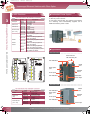
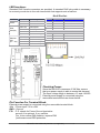
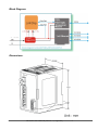
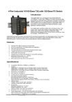
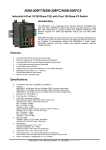
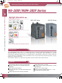
OT.316G!tfsjft`2/bj!!!311905039!!!¥V¥É!17;63;39
Unmanaged Ethernet Switches with Fiber Optics
NS-205F/NSM-205F Series
3
Unmanaged 4-Port Industrial 10/100 Base-T(X) with 100 Base-FX Fiber Switch
Unmanaged Ethernet Switches
Highlight Information
NS-205F/NSM-205F Series
NSM-205F Series
10/100
LAN
x4
Fiber
Optics
NS-205F Series
+70
x1
Only for NSM-205F Series
Wall &
DIN-Rail
Mount
Alarm
Contact
NS-205F/NSM-205F Series
Only for NS-205F Series
DIN-Rail
Mount
Introduction
The NS-205F/NSM-205F series is a Unmanaged 4-Port Industrial Ethernet(10/100Base-TX) to Fiber
Optics(100Base-FX) switch that secures data transmission by using fiber optic transmission to provide
immunity from EMI/RFI interference. It is used Ethernet for transmitting a signal up to 40 Km, and is the
perfect solution for applications where transmission must be protected from electrical exposure, surges,
lightning or chemical corrosion.
The Ethernet supports 10/ 100M auto-negotiation feature and auto MDI /MDIX function.
Introduction
Features
Automatic MDI / MDI-X crossover for plug-and-play
Each port supports both 10/100 Mbps speed auto
negotiation
Store-and-forward architecture
Full duplex IEEE 802.3x and half duplex backpressure
flow control
3.2Gbps high performance memory bandwidth
3-?
Frame buffer memory : 512 Kbit
Integrated look-up engine with dedicated 1 K unicast
MAC addresses
Supports +10~+30Vdc voltage
Supports operating temperatures from 0 ~ +70°C
DIN rail mount for industrial usage
ICP DAS Professional Provider of High Quality Industrial Data Acquisition and Control Products
OT.316G!tfsjft`3/bj!!!311905039!!!¥V¥É!1:;29;51
High Reliability Industrial Ethernet Switch for Rugged Environment
Introduction
Specifications
Technology
IEEE802.3, 802.3u, 802.3x
Processing Type
Store & forward wire speed switching - no delays
MAC Addresses
1024
Memory Bandwidth
3.2 Gbps
Flow Control
IEEE802.3x flow control, back pressure flow control
Interface
RJ45 Ports
10/100BaseT(X) auto negotiation speed, F/H duplex mode,
and auto MDI/MDIX connection
Fiber Optic Port
100 Base-FX(Multi-mode; SC connector)
LED Indicators
10/100M, Link/Act, Full duplex/Half duplex(Fiber Port)
Ethernet Isolation
1500 Vrms 1 minute
Frame Ground for EMS Protection
Yes
Multi mode fiber cables: 50/125, 62.5/125 or 100/140 Njm
Distance: 2 km, (62.5/125 Nj mrecommended) for full duplex
Multi Mode Fiber Optic
Wavelength: 1300 or 1310nm
Min. TX Output: -20 dBm
RX Sensitivity: -34 to -31 dBm
Single-mode fiber cables: 8.3/125, 8.7/125, 9/125 or 10/125 Njm
Distance: 15 km, (9/125 Njm mrecommended) for full duplex
Wavelength: 1300 or 1310nm
Min. TX Output: - 15 dBm
Max. TX Output: -8 dBm
RX Sensitivity: -36 to -31 dBm
Ethernet Transmission
distance
Ethernet: 2-pair UTP/STP Cat.3,4,5, EIA/TIA-568 100-ohm
Fast Ethernet: 2-pair UTP/STP Cat. 5, EIA/TIA-568 100-ohm
Power
Input Voltage Range
+10 ~ +30VDC (Non-isolation)
Power Consumption
0.14A@24VDC, +/- 5% arrowed with 100M Full duplex
LED Indicator
Yes
Protection
Power reverse polarity protection
Frame Ground for EMS Protection
Yes
NS-205F/NSM-205F Series
Max. TX Output: -14 dBm
Single Mode Fiber Optic
3
Unmanaged Ethernet Switches
Standards
Mechanical
Models
NS-205F Series
NSM-205F Series
Case
Plastic
Metal
Flammability
UL 94V-0
IP20
Dimensions (W x H x D)
64mm x 110mm x 98mm
72.5mm x 110mm x 102mm
Installation
DIN-Rail mount
DIN-Rail mount; Wall mounting
Environmental
Operating Temperature
0°C ~ +70°C
Storage Temperature
-20°C ~ +85°C
Ambient Relative Humidity
10% to 90% non-condensing
3-?
OT.316G!tfsjft`4/bj!!!311905039!!!¥V¥É!1:;32;43
Unmanaged Ethernet Switches with Fiber Optics
Introduction
Redundant Power Inputs
Introduction
LED Functions
3
NSM-205F Series LED Indicator Functions
Unmanaged Ethernet Switches
Color
Red On
Red Off
Yellow On
Full for P0
Yellow Off
Green On
Link for P0
Green Off
Yellow On
Ethernet Port Yellow Off
Green On
(P1 ~ P4)
Green Off
LED
PWR_OK
Description
Core Power is OK
Core Power is Off
Full Duplex
Half Duplex
Link/Act
Not Networking
Link/Act
Not Networking
Link to 100 Mbps
Link to 10 Mbps
Green On Power is being supplied to power
input PWR2
Both power inputs can be connected simultaneously
to live DC power sources.
If one power source fails, the other live sourceacts
as a backup, and automatically supplies all of
NSM-205F Series power needs.
Green Off Power is not being supplied to
power input PWR2
Yellow On Power is being supplied to power
input PWR1
Yellow Off Power is not being supplied to
power input PWR1
PWR2
PWR1
FAULT
Red On
Power is not being supplied to
power input PWR1 and PWR2
Red Off
Power is being supplied to power
input PWR1 and PWR2
Introduction
Appearance
NS-205F/NSM-205F Series
NSM-205F Series
Screw hole for
wall mounting kit
LED indicators
Metal
case
Fiber optics
port
RJ-45 ports
LED indicators
DIN-Rail
mount
Redundant
power input
NS-205F Series
NS-205F Series LED Indicator Functions
LED
Power
Fiber Port
(P0)
Ethernet Port
(P1 ~ P4)
3-?
Color
Red On
Red Off
Yellow On
Yellow Off
Green On
Green Off
Yellow On
Yellow Off
Green On
Green Off
Description
Power is On
Power is Off
Full Duplex Mode
Half Duplex Mode
Link/Act
Not Networking
Link/Act
Not Networking
Link to 100 Mbps
Link to 10 Mbps
LED indicators
Fiber optics
port
RJ-45 ports
Plastic
case
DIN-Rail
mount
LED indicators
ICP DAS Professional Provider of High Quality Industrial Data Acquisition and Control Products
Power input
OT.316G!tfsjft`5/bj!!!311905039!!!¥V¥É!1:;25;29
High Reliability Industrial Ethernet Switch for Rugged Environment
Introduction
Dimensions (Unit: mm)
NSM-205F Series
3
73.0
62.4
3.2
31.4
132.0
105.0
123.5
99.5
102.0
95.2
39.3
11.0
4.5
Left Side View
Front View
Right Side View
Back View
Bottom View
Top View
NS-205F Series
64.0
37.2
101.0
110.0
118.0
98.0
88.5
36.2
6.0
Left Side View
Front View
Right Side View
Back View
Bottom View
Top View
Introduction
Ordering Information
NS M -205F
-
-
NS-205F/NSM-205F Series
36.6
Unmanaged Ethernet Switches
39.3
M: Metal
Fiber Port Connector
Ordering Code
Definition
Models
Single Mode Distance
Operating Temperature
T: Multi mode ST connector
C: Multi mode SC connector
CS: Single mode SC connector
40: 40 km
Standard Models: 15 km
T: Operating Temp: -30 to +75°C
Standard Models: 0 to 70°C
NS-205FT, NSM-205FT
NS-205FC, NSM-205FC
NS-205FCS, NSM-205FCS
NS-205FCS-40
NSM-205FCS-40
NS-205FT-T, NSM-205FT-T
NS-205FC-T, NSM-205FC-T
NS-205FCS-T, NSM-205FCS-T
NS-205FCS-40T, NSM-205FCS-40T
Introduction
Accessories
GPSU06-6
KWM020-1824F
DIN-KA52F
24V/0.25A Power Supply, (No-mounting)
24V/0.75A Power Supply, (No-mounting)
24V/1A Power Supply, (With DIN-Rail mounting)
3-?
NS-205FT/NS-205FC/NS-205FCS
4-Port Industrial 10/100 Base-T(X) with 100 Base-FX Switch
Introduction:
The NS-205Fx is an unmanaged 4-Port Industrial Ethernet (10/100Base-TX) witch
Fiber (100Base-FX) Switch that secures data transmission by using fiber optic
transmission to provide immunity from EMI/RFI interference. It is used Ethernet for
transmitting a signal up to 2 Km (6,600 ft), and is the perfect solution for
applications where transmission must be protected from electrical exposure,
surges, lightning or chemical corrosion.
The NS-205Fx operates at either half or full duplex mode. In full duplex mode,
range is 2km with 62.5/ 125μm fiber cables; in half duplex mode, range is 412m
with 62.5/ 125μm fiber cables.
Single mode fiber cables:8.3/125, 8.7/125, 9/125 or 10/125 μm; 15 km for full
duplex. (NS-205FCS Only)
The Ethernet supports 10/ 100M auto-negotiation feature and auto MDI /MDIX
function
Features:
•
•
•
•
•
•
•
•
Automatic MDI / MDI-X crossover for plug-and-play
Each port supports both 10/100 Mbps speed auto negotiation
Store-and-forward architecture
Full duplex IEEE 802.3x and half duplex backpressure flow control
3.2Gbps high performance memory bandwidth
Frame buffer memory:512 Kbit
Integrated look-up engine with dedicated 1 K unicast MAC addresses.
DIN rail mount for industrial usage
Specifications:
•
•
•
•
•
•
•
•
•
•
•
•
Compatibility: IEEE 802.3, IEEE802.3u, IEEE802.3x
Interface:
NS-205FT: 10/100 Base-T(X) and 100 Base-FX(ST Connector; Multi-mode)
NS-205FC: 10/100 Base-T(X) and 100 Base-FX(SC Connector; Multi-mode)
NS-205FCS: 10/100 Base-T(X) and 100 Base-FX(SC Connector; Single-mode)
Ethernet Port: 10/100 Mbps x 4
Fiber Optic Port: 100 Mbps x 1
Provides LEDs for network and power monitoring
ESD Protection:
8 KV Contact Discharge
15KV Air-Gap Discharge
Fiber Optic Transmission distance:
Multi mode fiber:50/125, 62.5/125 or 100/140 μm
Multi mode fiber,412 m for half duplex, 2 km for full duplex
Single mode fiber cables:8.3/125, 8.7/125, 9/125 or 10/125 μm; 15 km for full duplex.
Ethernet Cables:
10 Base-T (Cat.3, 4,5 UTP cable; 100m Max.)
100 Base-TX (Cat.5 UTP cable; 100m Max.)
Environment:
Operating Temperature: 0 °C~ +70°C
Storage Temperature: -20 ~ +85°C
Relative Humidity: 10% to 90% non-condensing
Dimensions: 64 x 110 x 98 mm (W x H x D)
Power requirements: +10 to +30V DC (Removable Terminal Block)
Power consumption: 0.14A@24Vdc (+/- 5%, arrowed)
NS-205Fx User’s Manual (Version 1.0, Aug/2006) --------------- 1
LED functions:
Standard RJ45 female connectors are provided. A standard RJ45 plug cable is necessary
to connect your device to the unit since switch that supports auto crossover.
RJ-45 Pin-Out:
LED
Power
Fiber
Port(P0)
Ethernet
Port
(P1 ~ P4)
Color
Description
Pin#
Signal Name
Function
Red On
Power is On
1
TD+
Transmit Data
Red Off
Power is Off
2
TD-
Transmit Data
Yellow On
Full Duplex
3
RD+
Receive Data
Yellow Off
Half Duplex
4
NC
No Connection
Green On
Link/Act
5
NC
No Connection
Green Off
Not Networking
6
RD-
Receive Data
Yellow On
Link/Act
7
NC
No Connection
Yellow Off
Not Networking
8
NC
No Connection
Green On
Link to 100 Mbps
Green Off
Link to 10 Mbps
Checking Power:
Since the NS-205Fx consumes 3.3W Max, ensure
that your power supply is able to meets this demand.
The Input voltage range is between +10 and +30VDC.
External power supply is connected using the
removable terminal block as shown below:
Pin Function For Terminal Block:
External power supply is connected using the removable terminal block:
+Vs : Power input +10 to +30V
GND : Ground
F.G. :F.G. stands for Frame Ground (protective
ground). It is optional. If you use this
pin, it can reduce EMI radiation; improve EMI
performance and ESD protection.
NS-205Fx User’s Manual (Version 1.0, Aug/2006) --------------- 2
Application Note:
Figure shows common media conversion system network topologies. This figure is a
simple end-to-end configuration; it is easy way to verify proper operation of the media
converter(s), assuming that the Network Interface Cards (NIC’s) or Ethernet ports in each
PC/workstation end link partner are properly configured.
Figure:
Full / Half-Duplex Selection:
There are two modes of data transmissions, full-duplex and half-duplex transmission.
The data can be transmitted in both directions on a single carrier at
the same time when you select Full-duplex mode. But the data can only be
transmitted in one direction on a single carrier at the same time when you
select Half-duplex mode. You may select Full or half-duplex mode according to
your equipment requirement.
You can configure full or half-duplex NS-205Fx via Jumper. (Default: full-duplex).
JP1 Jumper
Description
Full-duplex ( Default)
Transmission Distance: 2Km
3
2
1
Half-duplex
Transmission Distance: 412m
3
2
1
NS-205Fx User’s Manual (Version 1.0, Aug/2006) --------------- 3
Block Diagram:
Dimensions:
NS-205Fx User’s Manual (Version 1.0, Aug/2006) --------------- 4