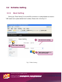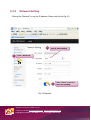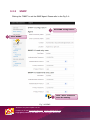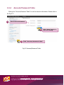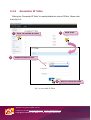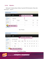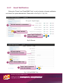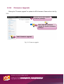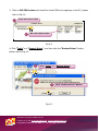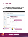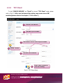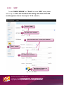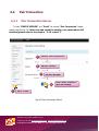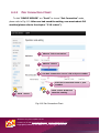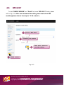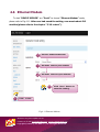
1
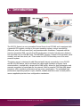
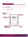
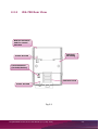
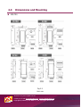
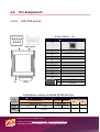
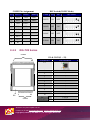
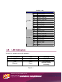
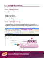
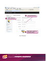
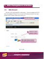
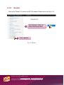
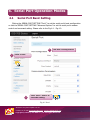
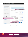
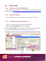
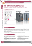
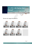
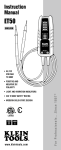
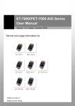
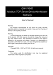
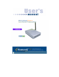
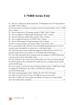
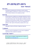
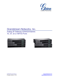
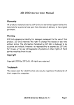
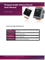
Programmable Device Server
User Manual
Version 0.0, Sep 2014
Service and usage information for
iDS-718i-D
Intelligent Device Server with 1 RS-232/422/485 (Isolated,
RoHS, DB9)
iDS-718iM-D CR
Intelligent Device Server with 1 RS-232/422/485 (Isolated,
Metal Case, RoHS, DB9)
iDS-728i-T CR
Intelligent Device Server with 2 RS-232/422/485 (Isolated,
RoHS, Terminal block)
iDS-728iM-T CR
Intelligent Device Server with 2 RS-232/422/485 (Isolated,
Metal Case, RoHS, Terminal block)
Programmable Device Server User Manual (V0.0, Sep. 2014)
-1-
Warranty
All products manufactured by ICP DAS are under warranty regarding defective materials
for a period of one year, starting from the date of delivery to the original purchaser.
Warning
ICP DAS assumes no liability for damages resulting from the use of this product. ICP DAS
reserves the right to change this manual at any time without notice. The information
furnished by ICP DAS is believed to be accurate and reliable. However, no responsibility is
assumed by ICP DAS for its use, nor for any infringements of patents or other rights of
third parties resulting from its use.
Copyright
Copyright © 2014 by ICP DAS. All rights are reserved.
Trademark
The names used for identification only may be registered trademarks of their respective
companies.
Contact US
If you have any question, please feel free to contact us.
We will give you quick response within 2 workdays.
Email: [email protected] , [email protected]
Programmable Device Server User Manual (V0.0, Sep. 2014)
-2-
Table of Contents
1.
INTRODUCTION ----------------------------------------------------------------------------------------------------------- 5
1.1
PACKING LIST ------------------------------------------------------------------------------------------------------------------ 6
1.2
FEATURES----------------------------------------------------------------------------------------------------------------------- 6
1.3
SPECIFICATIONS --------------------------------------------------------------------------------------------------------------- 6
1.4
ORDERING INFORMATION ----------------------------------------------------------------------------------------------------- 8
1.5
OPTION ACCESSORIES --------------------------------------------------------------------------------------------------------- 8
2.
GETTING STARTED ------------------------------------------------------------------------------------------------------- 9
2.2
FRONT VIEW ------------------------------------------------------------------------------------------------------------------- 9
2.2.1
iDS-700 Front View-------------------------------------------------------------------------------------------------- 9
2.2.2
iDS-700 Rear View -------------------------------------------------------------------------------------------------10
2.3
DIMENSIONS AND MOUNTING ----------------------------------------------------------------------------------------------- 11
2.4
PIN ASSIGNMENT ------------------------------------------------------------------------------------------------------------ 12
2.4.1
iDS-718 Series -------------------------------------------------------------------------------------------------------12
2.4.2
iDS-728 Series -------------------------------------------------------------------------------------------------------13
2.5
LED INDICATORS ------------------------------------------------------------------------------------------------------------ 14
2.6
CONFIGURATION METHOD -------------------------------------------------------------------------------------------------- 15
2.6.1
Factory Setting ------------------------------------------------------------------------------------------------------15
2.6.2
Setting IP Address --------------------------------------------------------------------------------------------------15
3.
WEB MANAGEMENT INTERFACE -----------------------------------------------------------------------------------17
3.1
WEB BROWSER--------------------------------------------------------------------------------------------------------------- 17
3.2
INITIALIZE SETTING --------------------------------------------------------------------------------------------------------- 18
3.2.1
Basic Setting ---------------------------------------------------------------------------------------------------------18
3.2.2
Network Setting -----------------------------------------------------------------------------------------------------19
3.2.3
SNMP ------------------------------------------------------------------------------------------------------------------20
3.2.4
Account/Password Table ------------------------------------------------------------------------------------------21
3.2.5
Accessible IP Table -------------------------------------------------------------------------------------------------22
3.2.6
Monitor ----------------------------------------------------------------------------------------------------------------23
3.2.7
Event Notification ---------------------------------------------------------------------------------------------------24
3.2.8
Firmware Upgrade--------------------------------------------------------------------------------------------------25
3.2.9
Restart ----------------------------------------------------------------------------------------------------------------26
4.
SERIAL PORT OPERATION MODES --------------------------------------------------------------------------------27
4.1
SERIAL PORT BASIC SETTING ----------------------------------------------------------------------------------------------- 27
4.2
VIRTUAL COM --------------------------------------------------------------------------------------------------------------- 29
4.2.1
Installing Virtual COM Utility--------------------------------------------------------------------------------------29
Programmable Device Server User Manual (V0.0, Sep. 2014)
-3-
4.2.2
Network Setting -----------------------------------------------------------------------------------------------------29
4.2.3
Configuring Virtual COM Ports -----------------------------------------------------------------------------------29
4.3
SOCKET MODES -------------------------------------------------------------------------------------------------------------- 31
4.3.1
TCP Server -----------------------------------------------------------------------------------------------------------31
4.3.2
TCP Client ------------------------------------------------------------------------------------------------------------32
4.3.3
UDP --------------------------------------------------------------------------------------------------------------------33
4.4
PAIR CONNECTION ----------------------------------------------------------------------------------------------------------- 34
4.4.1
Pair Connection Server --------------------------------------------------------------------------------------------34
4.4.2
Pair Connection Client ---------------------------------------------------------------------------------------------35
4.5
RFC2217 -------------------------------------------------------------------------------------------------------------------- 36
4.6
ETHERNET MODEM----------------------------------------------------------------------------------------------------------- 37
Programmable Device Server User Manual (V0.0, Sep. 2014)
-4-
1. Introduction
The iDS-700 Series is a new generation Device Server from ICP DAS and is equipped with
a powerful CPU module running on the open operating system, various connectivity
(Ethernet, micro SD and serial port) and communication interfaces. Compared with the
previous generation PDS, not only the CPU performance is higher but also more features
are improved such as 256 MB fl ash, 256 MB DDR3 memory, unique 64-bit hardware serial
number, and real-time clock, etc. These make the iDS-700 becoming one of the most
powerful system.
This device server is designed to add Ethernet and Internet connectivity to any RS-232
and RS-422/485 device, and to eliminate the cable length limitation of legacy serial
communication, coupled with a large built-in RAM buffer, allows for fast transmission and
prevents congestion of serial data on the network. Built-in powerful 720 MHz ARM-based
processor offers excellent performance at low power consumption. The preloaded highperformance operating system is open, flexible, scalable and allows user to easily add or
remove application/service from configuration mechanism.
Programmable Device Server User Manual (V0.0, Sep. 2014)
-5-
1.1 Packing List
The package includes the following items:
One (Programmable) Device Server hardware module
One software utility CD
One RS-232 console/download cable, CA-0903
One Quick Start Guide
Note: If any of these items are missed or damaged, contact the local distributors for
more information. Save the shipping materials and cartons in case you want to ship in
the future.
1.2
Features
Incorporate Serial Devices in an Ethernet network
Virtual COM for 32-bit and 64-bit Windows XP/2003/Vista/7
High-performance 720 MHz ARM-based Processor
256 MB DDR3 memory for data transmission and buffering
Zero Data Loss
UDP Support
RFC2217 support
Modem Emulator
Open, Flexible and Scalable Platform
SNMP Management Protocol
1.3
Models
Specifications
iDS-718i-D/iDS-718iM-D
iDS-728i-T/iDS-728iM-T
CPU Module
CPU
32-bit RISC, 720Mhz
RAM
256MB
Flash
256MB
Peripheral
microSD, RTC, Serial Number, Watchdog, Buzzer
Programmable Device Server User Manual (V0.0, Sep. 2014)
-6-
Communication Interface
COM1
COM2
RS-232/422/485
RS-232/422/485
(Isolate、5-Wire)
(5-Wire)
-
RS-232/422/485
(5-Wire)
COM3
-
-
COM4
-
-
Ethernet Port
10/100 Base-TX, RJ-45 port (Auto-negotiating, Auto MDI/MDI-X, LED indicators), PoE
(IEEE 802.3af, Class 1)
COM Port signals
RS-232-3w
RxD, TxD and GND; isolated
RS-232-5w
RxD, TxD, CTS, RTS and GND; isolated
RS-422
TxD+, TxD-, RxD+, RxD-, GND; Isolated
RS-485
D2+, D2-; Isolated;
COM Port Formats
Speed
921.6 Kbps Max.
Data Bit
5, 6, 7, 8
Parity
None, Even, Odd, Space, Mark
Stop Bit
1, 1.5, 2
Flow Control
RTS/CTS, XON/XOFF
Pull High/Low Resistor
1kΩ default, 150kΩ (for RS-485)
Software
Protocols
ICMP, IPv4/v6, TCP, UDP, DHCP, BOOTP,SSH, FTP, SFTP, DNS, DDNS, SNMP
V1/V2c/V3, HTTP, SMTP, ARP, PPPoE
Configuration method
Web, Serial Console, SSH Console
Virtual COM for Windows
Windows 2000, Windows XP/2003/Vista/2008/7/8 x86/x64, 2012 x64, XP Embedded
Virtual COM for Linux
Linux kernel 2.4.x, 2.6.x, 3.8.x
Management
SNMP MIB-II
Operation Modes
Virtual COM, TCP Server, TCP Client, UDP, Pair Connection, RFC2217, Terminal, Reverse
Telnet, TCP Modem, Modbus Gateway, Disabled
Authentication Method
Local, RAIDUS, TACACS+
Power Input
ESD Protection
Yes (with Frame Ground)
Protection
Power Reverse Polarity Protection
Required Supply Voltage
PoE or +12VDC ~ +48 VDC (non-regulated)
Power Consumption
3.5 W
Mechanism
Flammability
Fire Retardant Materials (UL94-V0 Level)
Dimension (W x H x D)
76 mm x 123 mm x 42 mm
Programmable Device Server User Manual (V0.0, Sep. 2014)
-7-
Installation
DIN-Rail
Environment
Operating Temperature
-25 ~ +75 °C
Storage Temperature
-40 ~ +80 °C
Humidity
5 ~ 90% RH, non-condensing
1.4
Ordering Information
iDS-718i-D
Intelligent Device Server with 1 RS-232/422/485 (Isolated, RoHS,
DB9)
iDS-718iM-D CR
Intelligent Device Server with 1 RS-232/422/485 (Isolated, Metal
Case, RoHS, DB9)
iDS-728i-T CR
Intelligent Device Server with 2 RS-232/422/485 (Isolated, RoHS,
Terminal block)
iDS-728iM-T CR
1.5
Intelligent Device Server with 2 RS-232/422/485 (Isolated, Metal
Case, RoHS, Terminal block)
Option Accessories
GPSU06U-6 CR
24 VDC/0.25 A, 6 W Power Supply
MDR-20-24 CR
24 VDC/1 A, 24 W Power Supply with DIN-R
DIN-KA52F-48 CR
48V/0.52A, 25 W Power Supply with DIN-Rail Mounting (RoHS, for
NS-205PSE)
CA-0903
9-Pin Female D-Sub and RS-232 Connector Cable, 30 cm Cable
CA-0910
9-Pin Female D-Sub and 3-wire RS-232 Cable, 1 m Cable
NS-205 CR
Unmanaged 5-port Industrial Ethernet Switch (RoHS)
NS-205PSE CR
Unmanaged Ethernet Switch with 4 PoE Ports and 1 RJ-45 Uplink
(RoHS)
Programmable Device Server User Manual (V0.0, Sep. 2014)
-8-
2. Getting Started
2.2
Front View
2.2.1
iDS-700 Front View
Serial Port
(COM1)
DIP Switch
LED Indicator
RJ-45 Jack for
10/100 M Ethernet
and PoE
Power
Fig 2-1
Programmable Device Server User Manual (V0.0, Sep. 2014)
-9-
2.2.2
iDS-700 Rear View
Robust insulated
and fire retard
ant case
DIN-Rail
Mounting
Frame Ground
CE Certification
(for PCB/device)
DIN-Rail Lock
Frame Ground
Fig 2-2
Programmable Device Server User Manual (V0.0, Sep. 2014)
- 10 -
2.3
Dimensions and Mounting
iDS-700
Fig 2-3
Unit: mm
Web Site: htt://www.icpdas.com.tw
Contact Us (E-mail):[email protected], [email protected]
Copyright @ 2013 by ICP DAS Co., Ltd. All Rights Reserved.
2.4
Pin Assignment
2.4.1
iDS-718 Series
E1 & CON1(1 ~ 12)
Terminal NO
Pin Assignment
E1
COM1
DIP Switch
1
E1
12
CON1
1
-
2
-
3
-
4
-
5
-
6
-
7
-
8
-
9
-
10
-
DC
11
P.PWR
(12~48V)
12
P.GND
Pull high/low resistors for the RS-422/RS-485 Port
DIP
Switch
ON
OFF
1
2
3
4
RS-485/RS-422
Pull High/Low
1 KΩ
5
6
RS-485
RS-422
Terminator
1 KΩ
120 Ω
120 Ω
Default
Web Site: htt://www.icpdas.com.tw
Contact Us (E-mail):[email protected], [email protected]
Copyright @ 2013 by ICP DAS Co., Ltd. All Rights Reserved.
7
8
M1
M0
0
0
1
1
COM1 Pin Assignment
DIP Switch(COM1 Mode)
Pin
RS232
RS422
RS485
1
DCD
TXD-
Data-
2
RXD
TXD+
Data+
3
TXD
RXD+
-
4
DTR
RXD-
-
5
GND
GND
GND
6
DSR
-
-
7
RTS
-
-
8
CTS
-
-
9
RI
-
-
2.4.2
COM1
M1
M0
RS232
ON
OFF
RS422
OFF
ON
RS485
OFF
OFF
Software
ON
ON
DIP Switch
iDS-728 Series
CON2
E1 & CON1(1 ~ 12)
1
Terminal NO
18
Pin Assignment
E1
E1
1
12
CON1
1
-
2
-
3
-
4
-
5
-
6
-
7
-
8
-
9
-
10
-
DC
(12V-48V)
11
P.PWR
12
P.GND
Web Site: htt://www.icpdas.com.tw
Contact Us (E-mail):[email protected], [email protected]
Copyright @ 2013 by ICP DAS Co., Ltd. All Rights Reserved.
CON2(1 ~ 18)
Terminal NO
COM2
COM1
2.5
Pin Assignment
1
RS-422_RxD2-
2
RS-422_RxD2+
3
RS-422_TxD2/D2-
4
RS-422_TxD2/D2+
5
RS-232_CTS2
6
RS-232_RTS2
7
RS-232_RxD2
8
RS-232_TxD2
9
GND2
10
RS-422_RxD1-
11
RS-422_RxD1+
12
RS-422_TxD1/D1-
13
RS-422_TxD1/D1+
14
RS-232_CTS1
15
RS-232_RTS1
16
RS-232_RxD1
17
RS-232_TxD1
18
GND1
LED Indicators
The iDS-700 contains three LED indicators..
LED In
LED Indicators
Color
Meaning
PWR
Red
Power is on
RUN
Green
OS is running
Ethernet
Green
Ethernet Cable is
Table 2-1
Web Site: htt://www.icpdas.com.tw
Contact Us (E-mail):[email protected], [email protected]
Copyright @ 2013 by ICP DAS Co., Ltd. All Rights Reserved.
connecting
2.6 Configuration Method
2.6.1
Factory Setting
1.default IP
IP:192.168.255.1
NetMask:255.255.255.0
Gateway:192.168.255.254
Protocol : icpdas protocol
2.6.2
Setting IP Address
Using web browser (IE or Chrome) and typing the default IP (192.168.255.1) to
connect to the iDS devices to set IP address(DHCP or Static). Please refer to the Fig 24、2-5:
Default IP Address
1
2
Default ID : admin
Password : admin
3
Click “Login” button to use the iDS-700
management interface.
Fig 2-4 Login
Web Site: htt://www.icpdas.com.tw
Contact Us (E-mail):[email protected], [email protected]
Copyright @ 2013 by ICP DAS Co., Ltd. All Rights Reserved.
2
1
Set IP Information
Click “Network“
3
Click “Save” button to
save the setting.
Fig 2-5 Network
Web Site: htt://www.icpdas.com.tw
Contact Us (E-mail):[email protected], [email protected]
Copyright @ 2013 by ICP DAS Co., Ltd. All Rights Reserved.
3. Web Management Interface
3.1
Web Browser
User can use the web browser(IE 8 or later version 、Chrome) to operate the iDS-700
series web management interface. User can input the IP address to connect to the “login”
interface of iDS-700 device. Please refer to the Fig 3-1:
1
iDS-700’s IP Address
2
Default ID : admin
Password : admin
3
Click “Login” button to use the
iDS-700 management interface.
Fig 3-1 Login
Web Site: htt://www.icpdas.com.tw
Contact Us (E-mail):[email protected], [email protected]
Copyright @ 2013 by ICP DAS Co., Ltd. All Rights Reserved.
3.2 Initialize Setting
3.2.1
Basic Setting
Clicking the “Basic Setting” to set the iDS’s hostname or enable/disable the function
“UDP search”(the system default don’t enable). Please refer to the Fig 3-2:
2
1
Set the basic setting
Click “Basic Setting”
3
Click “Save” button to
save the setting.
Fig 3-2 Basic Setting
Web Site: htt://www.icpdas.com.tw
Contact Us (E-mail):[email protected], [email protected]
Copyright @ 2013 by ICP DAS Co., Ltd. All Rights Reserved.
3.2.2
Network Setting
Clicking the “Network” to set the IP address. Please refer to the Fig 3-3:
2
1
Set IP Information
Click “Network”
3
Click “Save” button to
save the setting.
Fig 3-3 Network
Web Site: htt://www.icpdas.com.tw
Contact Us (E-mail):[email protected], [email protected]
Copyright @ 2013 by ICP DAS Co., Ltd. All Rights Reserved.
3.2.3
SNMP
Clicking the “SNMP” to set the SNMP Agent. Please refer to the Fig 3-4:
2
1
Set SNMP Configuration
Click “SNMP”
3
Click “Save” button to
save the setting.
Fig 3-4 SNMP
Web Site: htt://www.icpdas.com.tw
Contact Us (E-mail):[email protected], [email protected]
Copyright @ 2013 by ICP DAS Co., Ltd. All Rights Reserved.
3.2.4
Account/Password Table
Clicking the “Account/Password Table” to set the account information. Please refer to
the Fig 3-5:
2
Set account information
3
1
Click “Account/Password Table”
Fig 3-5 Account/Password Table
Web Site: htt://www.icpdas.com.tw
Contact Us (E-mail):[email protected], [email protected]
Copyright @ 2013 by ICP DAS Co., Ltd. All Rights Reserved.
Click “Save” button to
save the setting.
3.2.5
Accessible IP Table
Clicking the “Accessible IP Table” to enable/disable the rules of IP filter. Please refer
to the Fig 3-6:
1
3
2
Click “Accessible IP Table
Click “Edit”
Enable/Disable IP filer
4
Save or Cancel the rules
Fig 3-6 Accessible IP Table
Web Site: htt://www.icpdas.com.tw
Contact Us (E-mail):[email protected], [email protected]
Copyright @ 2013 by ICP DAS Co., Ltd. All Rights Reserved.
3.2.6
Monitor
Clicking the “Line/Async/Async Setting” to get the COM’s information. Please refer
to the Fig 3-7、Fig 3-8:
Get COM’s information
2
1
Click “Async”
Fig 3-7 Async
2
1
Get COM’s information
Click “Async Setting”
Fig 3-8 Async Setting
Web Site: htt://www.icpdas.com.tw
Contact Us (E-mail):[email protected], [email protected]
Copyright @ 2013 by ICP DAS Co., Ltd. All Rights Reserved.
3.2.7
Event Notification
Clicking the “Events” and “Email/SNMP Trap” to set the function of events notification
and inform the system administrator. Please refer to the Fig 3-9、Fig 3-10:
2
Set the method of notification
1
Click “Events”
Click “Save” button to
save the setting.
3
Fig 3-9 Events
2
1
Set the network
environment of server
Click “Email/SNMP Trap”
3
Click “Save” button to
save the setting.
Fig 3-10 Email/SNMP Trap
Web Site: htt://www.icpdas.com.tw
Contact Us (E-mail):[email protected], [email protected]
Copyright @ 2013 by ICP DAS Co., Ltd. All Rights Reserved.
3.2.8
Firmware Upgrade
Clicking the “Firmware upgrade” to update the iDS’s firmware. Please refer to the Fig
3-11:
2
Please choose the icpdas’s
firmware package.
3
1
Click “Upload” button to
upload the icpdas’s firmware
package.
Click “Firmware upgrade”
Fig 3-11 Firmware upgrade
Web Site: htt://www.icpdas.com.tw
Contact Us (E-mail):[email protected], [email protected]
Copyright @ 2013 by ICP DAS Co., Ltd. All Rights Reserved.
3.2.9
Restart
Clicking the “Restart” to reboot the iDS-700 module. Please refer to the Fig 3-12:
Click “Restart” button to
reboot iDS-700 module.
2
1
Click “Restart”
Fig 3-12 Restart
Web Site: htt://www.icpdas.com.tw
Contact Us (E-mail):[email protected], [email protected]
Copyright @ 2013 by ICP DAS Co., Ltd. All Rights Reserved.
4. Serial Port Operation Modes
4.1
Serial Port Basic Setting
Clicking the SERIAL PORT SETTING “Port1” to set the serial port’s basic configuration
or click the SERIAL PORT SETTING “Advanced Options” to set the serial port’s modem
control and command setting. Please refer to the Fig 4-1、Fig 4-2:
2
1
Set Port’s Configuration
Click “Port1”
3
Click “Save” button to
save the setting.
Fig 4-1 Port1
Web Site: htt://www.icpdas.com.tw
Contact Us (E-mail):[email protected], [email protected]
Copyright @ 2013 by ICP DAS Co., Ltd. All Rights Reserved.
2
1
Set Port’s Advanced Options
Click Port1’s Advanced Options
3
Click “Save” button to
save the setting.
Fig 4-2 Port1’s Advanced Option
Web Site: htt://www.icpdas.com.tw
Contact Us (E-mail):[email protected], [email protected]
Copyright @ 2013 by ICP DAS Co., Ltd. All Rights Reserved.
4.2
Virtual COM
4.2.1
Installing Virtual COM Utility
Please innstall VxComm Utility(v 2.12.07 or later version), the software can download
from below web link: http://ftp.icpdas.com/pub/cd/8000cd/napdos/driver/vxcomm_driver/
4.2.2
Network Setting
Please refer to chapter “3.2.2” to set network environment of iDS-700 modules.
4.2.3
Configuring Virtual COM Ports
Please refer to below steps to set and use the virtual COM ports.
1. Double click the VxComm Utility shortcut on the desktop.
2. Click the “Add Server[s]” button to connect to the iDS-700, then user assign a COM
Port number and click “OK” to save your settings, please refer to Fig 4-3.
1
Click “Add Servers” button
3
2
Click “OK” to run
the setting.
Set COM’s Name
Fig 4-3
Web Site: htt://www.icpdas.com.tw
Contact Us (E-mail):[email protected], [email protected]
Copyright @ 2013 by ICP DAS Co., Ltd. All Rights Reserved.
3. Click on iDS-700’s name and check the virtual COM port mappings on the PC, please
refer to Fig 4-4.
1
Click iDS-700’s name
2
iDS-700 COM’s Name
Fig 4-4
4. Click “Tools” >> “Restart Driver”, and then click the “Restart Driver” button, ,
please refer to Fig 4-5.
1
Click “Tools” >> “Restart Driver”
2
Click “Restart Driver” Button
Fig 4-5
Web Site: htt://www.icpdas.com.tw
Contact Us (E-mail):[email protected], [email protected]
Copyright @ 2013 by ICP DAS Co., Ltd. All Rights Reserved.
4.3
Socket Modes
4.3.1
TCP Server
To click “DEVICE SERVER” >> “Port1” to choose “TCP Server” mode, please
refer to Fig 4-6. After user had saved the setting, user must reboot iDS
modules(please refer to the chapter “3.2.9 restart”).
2
Choose “TCP Server”
3
1
Click “Port1”
4
Set “Server Options”
Click “Save” button to
save the setting.
Fig 4-6 TCP Server Mode
Web Site: htt://www.icpdas.com.tw
Contact Us (E-mail):[email protected], [email protected]
Copyright @ 2013 by ICP DAS Co., Ltd. All Rights Reserved.
4.3.2
TCP Client
To click “DEVICE SERVER” >> “Port1” to choose “TCP Client” mode, please
refer to Fig 4-7. After user had saved the setting, user must reboot iDS
modules(please refer to the chapter “3.2.9 restart”).
2
3
1
Choose “TCP Server”
Set iDS’s port number
4
Set remote server’s IP and port number
5
Set iDS’s port number
Click “Port1”
6
Click “Save” button to
save the setting.
Fig 4-7 TCP Client Mode
Web Site: htt://www.icpdas.com.tw
Contact Us (E-mail):[email protected], [email protected]
Copyright @ 2013 by ICP DAS Co., Ltd. All Rights Reserved.
4.3.3
UDP
To click “DEVICE SERVER” >> “Port1” to choose “UDP” mode, please
refer to Fig 4-8. After user had saved the setting, user must reboot iDS
modules(please refer to the chapter “3.2.9 restart”).
2
3
Choose “UDP”
Set iDS’s port number
4
1
Set remote host’s IP and port number
Click “Port1”
5
Set iDS’s port number
6
Click “Save” button to
save the setting.
Fig 4-8 UDP Mode
Web Site: htt://www.icpdas.com.tw
Contact Us (E-mail):[email protected], [email protected]
Copyright @ 2013 by ICP DAS Co., Ltd. All Rights Reserved.
4.4
Pair Connection
4.4.1
Pair Connection Server
To click “DEVICE SERVER” >> “Port1” to choose “Pair Connection” mode,
please refer to Fig 4-9. After user had saved the setting, user must reboot iDS
modules(please refer to the chapter “3.2.9 restart”).
2
Choose “Pair Connection”
3
Choose “Server”
4
Set Port Number
5
1
Click “Save” button to
save the setting.
Click “Port1”
Fig 4-9 Pair Connection Server
Web Site: htt://www.icpdas.com.tw
Contact Us (E-mail):[email protected], [email protected]
Copyright @ 2013 by ICP DAS Co., Ltd. All Rights Reserved.
4.4.2
Pair Connection Client
To click “DEVICE SERVER” >> “Port1” to choose “Pair Connection” mode,
please refer to Fig 4-10. After user had saved the setting, user must reboot iDS
modules(please refer to the chapter “3.2.9 restart”).
2
Choose “Pair Connection”
3
Choose “Client”
4
Set Pair Connection server’s IP and port number
5
1
6
Click “Port1”
Set Pair Connection client’s port
number
Click “Save” button to
save the setting.
Fig 4-10 Pair Connection Client
Web Site: htt://www.icpdas.com.tw
Contact Us (E-mail):[email protected], [email protected]
Copyright @ 2013 by ICP DAS Co., Ltd. All Rights Reserved.
4.5
RFC2217
To click “DEVICE SERVER” >> “Port1” to choose “RFC-2217” mode, please
refer to Fig 4-10. After user had saved the setting, user must reboot iDS
modules(please refer to the chapter “3.2.9 restart”).
2
3
Choose “RFC-2217”
Set iDS’s port number
4
1
Click “Save” button to
save the setting.
Click “Port1”
Fig 4-10
Web Site: htt://www.icpdas.com.tw
Contact Us (E-mail):[email protected], [email protected]
Copyright @ 2013 by ICP DAS Co., Ltd. All Rights Reserved.
4.6 Ethernet Modem
To click “DEVICE SERVER” >> “Port1” to choose “Ethernet Modem” mode,
please refer to Fig 4-11. After user had saved the setting, user must reboot iDS
modules(please refer to the chapter “3.2.9 restart”).
2
Choose “Ethernet Modem”
3
Set iDS’s Dial-in port number
4
Set iDS’s Dial-Out port number
5
Click “Save” button to
save the setting.
1
Click “Port1”
Fig 4-11 Ethernet Modem
Web Site: htt://www.icpdas.com.tw
Contact Us (E-mail):[email protected], [email protected]
Copyright @ 2013 by ICP DAS Co., Ltd. All Rights Reserved.