1
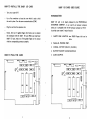
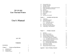
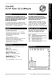
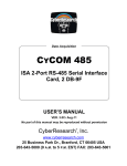
CONTENTS INTRODUCTION ................................. 1 HOW TO INSTALL THE MULTI I/O CARD ............. 2 HOW TO PLUG THE CARD ........ , ....•.......... 2 A BRIEF DESCRIPTION ABOUT MULTI I/O CARD....... 4 HOW TO USE THE MULTI I/O CARD ................ 5 GAME CONTROL ADAPTER ........................ 8 GAME CONTROL ADAPTER PIN ASSIGNMENTS......... 8 THE PIN ASSIGNMENT FOR GAME CONTROL ADAPTER.................................... 8 LOCATION OF PORT .................................. 9 PC TIMER 1.3 USER GUIDE........................ 10 HOW TO INSTALL THE BABY 1/0 CARD BABY 1/0 CARD USER GUIDE Turn your system OFF. INTRODUCTION Use a flat screwdriver to loose the screw which is used to hold the card in place.· Turn the screw counterclockwise (COW). Plug the card into the expansion slot. BABY I/O card is ckt board produced by the PERIPHERALS ENTERPRISE COMPANY, it can used by all personal computer which are in compatible with 16 BIT personal computer or PC/XT It provides your system S majors function: Notice, there are 31 golden fingers which allow you to connect the mainboard with the BABY I/O card. When you install your BABY I/O card, make sure if the golden fingers aro in contact with the corresponding connector properly. 1. FLOPPY DISK ADAPTER: two DS/DD floppy disk Can be drive. HOW TO PLUG THE CARD ASYN',c:::J""":c:::::J = -=- c 0ill0 PARALLEL PRINTER PORT. 2 SERIAL I/O PORT (RS.232-1, RS-232·2). 4. BATIERY BACKUP CLOCK/CALENDAR. S. GAME ADAPTER. = ~~~~*= W*O ~ [Jill[l 2. 3. If oon~ tJ [j l:J i ASYN',c:::J""":c:::::J 00#0 c = -=- = ~~~~;-r*= ~ [Jill[l 0ill0 If oon~ tJ [j l:J i 2 Use the flat screwdrive to fix the card. Turn the screw clock A BRIEF DESCRIPTION ABOUT BABY I/O CARD wise (CW). Consider the following figure of BABY 1/0 card: DISK ADAPTER: Allow you to plug flag cable driver two FDD. RS-232-2 (ASYN 2): Allow you connect standard RS-232 interface BABY I/b Card n:;~~~~~~;;;===========,"==1 , to transmit and receive data in serial mode. RS-232-1 (ASYN 1): Allow you connect standard RS-232 interface. INTERRUPT LEVEL SELECTIVE AREA. PRINTER PORT: Allows you to connect the parallel printer. GAME PORT: Allows ioy-stick connect there. Configuration Jumper TIMER ASYN 1 ASYN. 2 Horizontal Close Vertical Close GAME ENABLE LC.~~-'--I--'.J.~~'---l-=-=:-::"'Horizontal Close Vertical Close 4 HOW TO USE THE BABY I/O CARD 1. PIN DEFINE: FLOPPY DISK -STROBE DATA 0 DATA 1 DATA 2 DATA 3 DATA 4 DATA 5 DATA 6 9 DATA 7 1 2 3 4 5 Use flag disk cable please check pin 1 make correct to connect disk port golden pin. Cable other hand have two 34 pin female disk connector distance cable longer connector is DRIVER A. ~c=::::J AS""U,~c::::::J a:=:::J -t:::::> a::::::::J ~ ~ ~ O!!!!:l ~ ~:***= [ ~~~O*,+O~~~I --~,n 0n~ tJtJtJ ~ jl ' - - - - - - - - ' ~~~ 6 -l'---____--'n 2. PARALLEL PRINTER INTERFACE The parallel printer interface is designed to connect printer. Parallel printer supports the graphics function by driver software. User device jumper to enable/disable enable or disable your printer. INTERRUPT SELECT JUMPER -ACK +BUSY +PE +SELECT -AUTO FD XT -ERROR -INT -SELECT INPUT 18-26 GROUND SERIAL INTERFACE RS-232 CONNECTOR The serial interface is standard EIA RS-232 interface that is fully programmable and support PC/XT asychronous. The BAUD rate (bit/sec) can be set from 50 to %00. - There are 2 serial port (RS-232-1 and RS-232-2), normal the card provides you all component for RS-232-1; but RS 232-2 is optional. You must provide all support ICs by yourself (8250 etc.) Use DEVICE SELECT JUMPER to define either RS-232-1 or RS-232-2 as COM 1 or COM 2. But you can't define RS-232-1 and RS-232-2 at the same device. COM 1 is assigned to port 3F8H, COM2 is assign to port 2F8H. Use INTERRUPT SELECT JUMPER to assign the interrupt level to COM function. Printer: ~l 5 W=LPTl : is enable. Normally, COM 1, data terminal equipment node, level 4 8 [5-7[ 3. 10 11 12 13 14 15 16 17 = LPT2: is enable. interrupt is selected. 8 all open is disable. 5 7 6 PIN ASSIGNMENTS OF ASYN. PORT GAME CONTROL ADAPTER ASYN. PORT PIN PIN PII'< PIN PIN 1: 2: 3: 4: 5: CARRIER DEl. RX DATA TX DATA EIA DTR GROUND PIN 6: PIN 7: PIN 8: PIN 9: PINlO: EIA DSR EIA RTS EIA CTS RING IDC N.C. The game adapter allows you to attach two JOY-STICK to PC, the paddles must have range of 0 to lOOk o~ms. Experience has show lot of variation even in PC/XT compatible JOY-STICK, so you should in JOY-STICK with a centering mechanism so that you adjust your JOY-STICK to the program. GAME CONTROL ADAPTER PIN ASSIGNMENTS The BABY I/O card uses a 15 pin female "D" connector for the game control adapter. THE PIN ASSIGNMENT FOR GAME CONTROL Asyn 1: 12 ~4I 11 13 10 I ADAPTER = = COM1 : is enable. 12 Game: 14 COM3: is enable 9 2 14 all open is disable 9 11 Close is enable. Open is disable. 13 1S PIN MALE "D" CONNECTOR Asyn 2: ~ WJ 18 G]0 I = COM2: is enable 17 19 16 18 20 I COM4: is enable. 15 20 all open is disable. 15 17 19 8 LOCATION OF PORT GAME ADAPTER: PRINTER PORT ASYN 1 PORT ASYN 2 PORT TIMER PC TIMER 1.3 USER GUIDE &H200 LPTI LPT2 COMI COM2 COM2 COM4 TIMI TlM2 : = &H378 , INT = IRQ7 : = &H278 , INT = IRQ5 INT = IRQ4 : = &H3F8 : = &H3E8 INT = IRQ4 INT = IRQ3 : = &H2F8 INT = IRQ3 : = &H2E8 : = &H240 : = &H340 INTRODUCTION Consider the hardware configuration of the multifunction card, you can see a battery powered CLOCK/CALENDAR. You may ask what is its function and how to use it? The answer can be found in this section. You can use the TIMER.COM program to operate it. THE FUNCTION OF TIMER.COM PROGRAM - Allows you to initialize the date and time in the CLOCK/ CALENDAR device. A rechargeable battery provides the power to the CLOCK/CALENDAR still works and the time and date that you set in last time are still maintained. - Allows you to set the date and time in the system. - Reports you the current status of the CLOCK/CALENDAR. Timer: m 6 = TIMl : is enable. 14-61 3 4 =TlM2: is enable. 6 all open is disable. 3 GETTING 5TART There are 2 ways to start the timer program: 1) Type in TIMER command and option. 9 10 2) Create an AUTOEXEC.BAT file, this file will auto execute once you reboot your system. a) If you haven't an AUTOEXEC.BAT file on your diskette, create it; first type in COPY CON: AUTOEXEC.BAT Once you have created the AUTOEXEC.BAT file, When you reset your system, the TIMER/S in the AUTOEXEC.BAT file will transfer the time in the CLOCK/CALENDAR into the system. The screen will display: A> TIME/S •• PC TIMER 1.3" Current time i.s XX:XX:XX:XX Current date is XXX XX - XX - XX Press ENTE R key Then type in TlMER/S [ctr] + Z (or Key in the F6 function key) Press ENTER key b) If the AUTOEXEC.BAT file already exists on your diskette, you will need to add one line to the file. You must have the line editior EDLIN program on your diskette. The A > prompt redisplays again and you have created an AUTOEXEC.BAT file. Type in The screen's displaying: Type in A > Press ENTER key EDLIN AUTOEXEC.BAT Press ENTER key Ii A COpy CON: AUTOEXEC.BAT TIMER/S Z 1 File(s) Copied > Type in TIMER/S Press ENTER key Type in In the above commands, the first command line tells DOS to copy the information entered on the keyboard into the AUTOEXEC. BAT file. The second command line enter the TIMER/S program so that once you run the AUTOEXEC.BAT file the TIMER/S will ex· ecute automatically. The [Ctrl + Z] or F6 means that you can press the Ctrl key and Z key together or you only press F6 key. This causes the system that additional keyboard information is not into the file and causes the information to be written into the file. 11 E Press ENTE R key The A > prompt redisplays again. You have created an AUTOEXEC.BAT file with the TIMER/S program in it. The screen displays as follow: 12 they are correct, the TIMER program set them onto the CLOCK/CALENDAR device, otherwise an error message is displayed and you have to try again. If you don·t want make any change, just press the ENTER key. The screen's displaying are shown in the following figures: A> EDLIN AUTOEXEC.BAT 'Ii i : 'TIMER/S 2:' C 'E •• PC TIMER 1.3" Current time is XX:XX:XX:XX: A> Enter new time: TIME'S COMMAND TIMER/? Help menu, provides you a listing of TIMER'S command. The TIME HELP MUNU is displayed as follow: After entered the date correctly and press ENTER key the screen display: •• PC TIMER 13" Time Help Menu: TIMER TIMER/I TIMER/S TIME/? TIMER FORMAT DATE FORMAT Read current time & date. Initial setting current time & date to system clock. Set current time & date to system clock. Help menu. HOUR, MINUTE: SECOND (Every item have two digits) MONTH - DAY - YEAR (Every item have two digits) •• PC TIMER 1.3" Current time is XX:XX:XX:XX Current date is XXX XX - XX - XX TIME FORMAT:XX:XX:XX hour minute second Let us discuss the commands shown in the HELP menu NOTE: TIMER Reads current time and date and displays the date and time. The screen displays as follow: •• PC TIME 13" Current time is XX:XX:XX:XX Current date is XXX XX - XX - XX TIMER/I Initializes the CLOCK/CALENDAR device on the BABY I/O card. It will first display the time and date currently exist and ask you to enter the new time and date. After you have entered the time and date. the program will check whether their formats are correct. If 13 The TIMER program only accepts 8 characters 2 digits for each item. 2 characters to separate the digits, you can use any characters to separate the items. But the standard form is use" HOUR range from 0-23 MINUTE range from 0-59 SECOND range from 0-59 14 DATE FORMAT: MONTH - DATE - YEAR MONTH range from 1 -12 DATE range from 1-31 YEAR range from 0-99 (When you type in 0-79, the program considers it as year 2000- 2079; when you type in 80-99, the program considers it as 1980 1999.) NOTE: Don't use alphabet. The TIMER program only accepts 8 characters: 6 digits (2 for each item). 2 characters that separate each item. If you had entered the invalid format of time or date the screen will display the following message. Invalid time Enter new time: Invalid date Enter new date: You have to try again or just press the ENTER key to skip it. you just press the ENTER key to skip it, the original time and date remain unchange. TIMERjS This command displays the time and date and sets the system time and date. It is convenient to insert it into the AUTOEXEC.BAT file to automatically display and set the system time when the system is booted or reset. 15