1
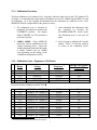
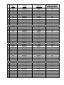
Valhalla Scientific, Inc. Calibration Laboratory 12127 Kirkham Rd Poway, CA 92064 (858) 457-5576 VALHALLA SCIENTIFIC MODELS 2703 – 2705 ROUTINE MAINTENANCE AND CALIBRATION PROCEDURE 1 GENERAL.................................................................................................................................................................3 2 PERIODIC MAINTENANCE .................................................................................................................................3 3 CALIBRATION ........................................................................................................................................................3 3.1 MODEL 2703 CALIBRATION ...............................................................................................................................4 3.1.1 Required Test Equipment..............................................................................................................................4 3.1.2 Calibration Configuration Switch.................................................................................................................4 3.1.3 Calibration Procedure..................................................................................................................................5 3.1.4 Calibration Cycle - Sequence of Cal Points .................................................................................................5 3.2 MODEL 2705 CALIBRATION ...............................................................................................................................8 4 REMOTE CALIBRATION VIA THE GPIB .........................................................................................................8 2 1 General This section contains routine maintenance procedures designed to provide maximum Model 2703/05. Included are cleaning instructions and a calibration procedure. throughout this section that the calibration technician is familiar with operation of described in Section 6. If desired, the Model 2703/05 may also be returned to maintenance and calibration traceable to NIST. utility from the It is assumed the 2703/05 as the factory for 2 Periodic Maintenance As a recommendation, the Model 2703/05 should be operated in a dust-free, clean environment. However, if the unit is exposed to contaminants periodic cleaning will be required. Loose dirt or dust on the exterior surfaces may be removed with a dry soft cloth or brush. Any remaining residue may be removed with a soft cloth dampened in a mild soap and water solution. Do not use abrasive cleaners! The front panel may be cleaned with a soft cloth and a glass cleaner such as Windex or its equivalent. Do not use petroleum based cleaners on the front panel! If required, the interior may be cleaned by blowing with dry compressed air. The filter for the intake fan is removable and should be kept clean to ensure maximum airflow. The filter element may be cleaned by blowing with compressed air. Replacement filter elements are available as Valhalla Stock #05-10494. If the unit becomes heavily contaminated with dirt or other residue, a complete overhaul is recommended. Contact your local Valhalla Scientific representative or the factory for details. 3 Calibration The calibration procedure should be performed on a regular basis (annually is recommended) to ensure that the Model 2703/05 remains within the specifications set forth in Section 2 of its user-service manual. The 2703/05 should be allowed to warm-up for a minimum of one (1) hour with the covers in place in a stable environment prior to beginning the procedure. Due to the differences between the procedures for the Model 2703 and Model 2705, a separate procedure is provided for each instrument. Refer to section 3.1 for the 2703, and to section 3.2 for the 2705 procedure. 3 3.1 Model 2703 Calibration This section describes routine calibration of the Model 2703. The procedure should be performed with all covers in place using the front panel controls. Adjustment of the internal potentiometers may be required following repair or component replacement. If internal adjustments are required, contact the factory for advice. 3.1.1 Required Test Equipment Performance of the calibration procedure requires the following items: ¾ A precision AC measurement standard such as the DATRON 4920. or ¾ A thermal-transfer AC measurement system such as the HOLT 6B, in conjunction with a DC voltage calibrator such as the Valhalla Model 2701C. )Most precision DVM's lack the accuracy, linearity, and bandwidth necessary to calibrate the Model 2703/05. Use of one of the devices listed above or its exact equivalent is required in order to calibrate the 2703/05 to the full range of its specifications. 3.1.2 Calibration Configuration Switch The 2703/05 includes a switch that allows the user to select between a short or long calibration cycle, and to set the .12V range calibration voltage. The long cycle should be used for routine calibration in order to maintain the full range of specifications for the instrument. The short cycle may be used as a rough calibration following maintenance, but is not recommended for routine calibration. The switches are accessed by removing the top cover of the instrument and locating the 5-pole DIP switch block on the left-hand microprocessor PCB. With the instrument turned off, set the switches as follows (in order from top to bottom): _Always OPEN for 2703. Always CLOSED for 2705. _Leave OPEN for the long calibration cycle of the 2703. Set CLOSED for the short cycle of 2703 (refer to Table 8-1). For 2705, leave this switch in the CLOSED position. _Leave OPEN always. _If OPEN, causes the 2703/05 to calibrate the .12V range at 1 volt instead of .1 volts. This is to ensure compatibility with most thermal voltmeters. Leave this switch CLOSED for normal calibration. _Not used. 4 3.1.3 Calibration Procedure The short calibration cycle consists of five "cal points", while the long cycle for the 2703 consists of 59 cal points. It is important that a high quality shielded lead set such as Valhalla Option "BBL" be used for calibration. It is also strongly recommended that the instrument be connected in the 4-wire (REMOTE SENSE) configuration for the greatest accuracy. 1. The calibration cycle is activated by turning the rear panel key switch to the CALIBRATE position. The display flashes "cal 2703" (or 2705) and moves to the first cal point. 3. After completing the adjustment, enter the correction by pressing the STANDBY/OPERATE switch again. The instrument moves to the next cal point. 2. .100000, 1000Hz Select OPERATE mode and wait for stabilization of the voltage measuring device. Adjust the voltage amplitude knobs until the output is exactly .100000 volts (or 1.00000 volts depending on the setting of the "calibration configuration switch"). 4. Each cal point is calibrated in a similar manner. Table 3.1.4 lists the sequence of events in the calibration cycles. 3.1.4 Calibration Cycle - Sequence of Cal Points 1 2 3 4 5 Range Voltage Frequency 1 1.2 V .12 V 12 V 120 V 1200 V 1.00000 V .100000 V (or 1.00000 V) 10.0000 V 100.000 V 1000.00 V 1000 Hz 1000 Hz 1000 Hz 1000 Hz 10 Hz OPERATE Keypress Required? Yes Yes Yes Yes Yes 10 kHz 20 kHz 30 kHz 40 kHz 50 kHz 60 kHz 70 kHz 80 kHz 90 kHz 100 kHz 10 Hz Yes No No No No No No No No No No End cycle for short calibration, and for 2705. 6 7 8 9 10 11 12 13 14 15 16 1 .12 V .12 V .12 V .12 V .12 V .12 V .12 V .12 V .12 V .12 V .12 V .100000 V (or 1.00000 V) .100000 V (or 1.00000 V) .100000 V (or 1.00000 V) .100000 V (or 1.00000 V) .100000 V (or 1.00000 V) .100000 V (or 1.00000 V) .100000 V (or 1.00000 V) .100000 V (or 1.00000 V) .100000 V (or 1.00000 V) .100000 V (or 1.00000 V) .100000 V (or 1.00000 V) For 2705, leave the master set to 100Hz for all cal points. 5 Range Voltage Frequency 17 18 19 20 21 22 23 24 25 26 27 1.2V 1.2V 1.2V 1.2V 1.2V 1.2V 1.2V 1.2V 1.2V 1.2V 1.2V 1.00000 V 1.00000 V 1.00000 V 1.00000 V 1.00000 V 1.00000 V 1.00000 V 1.00000 V 1.00000 V 1.00000 V 1.00000 V 10 kHz 20 kHz 30 kHz 40 kHz 50 kHz 60 kHz 70 kHz 80 kHz 90 kHz 100 kHz 10 Hz OPERATE Keypress Required? Yes No No No No No No No No No No 28 29 30 31 32 33 34 35 36 37 38 12 V 12 V 12 V 12 V 12 V 12 V 12 V 12 V 12 V 12 V 12 V 10.0000 V 10.0000 V 10.0000 V 10.0000 V 10.0000 V 10.0000 V 10.0000 V 10.0000 V 10.0000 V 10.0000 V 10.0000 V 10 kHz 20 kHz 30 kHz 40 kHz 50 kHz 60 kHz 70 kHz 80 kHz 90 kHz 100 kHz 10 Hz Yes No No No No No No No No No No 39 40 41 42 43 44 45 46 47 48 49 120 V 120 V 120 V 120 V 120 V 120 V 120 V 120 V 120 V 120 V 120 V 100.000 V 100.000 V 100.000 V 100.000 V 100.000 V 100.000 V 100.000 V 100.000 V 100.000 V 100.000 V 100.000 V 10 kHz 20 kHz 30 kHz 40 kHz 50 kHz 60 kHz 70 kHz 80 kHz 90 kHz 100 kHz 10 Hz Yes No No No No No No No No No No 50 1200 V 1000.00 V 100 Hz 51 1200 V 1000.00 V 200 Hz 52 1200 V 1000.00 V 300 Hz 53 1200 V 1000.00 V 400 Hz 54 1200 V 1000.00 V 500 Hz 55 1200 V 1000.00 V 600 Hz 56 1200 V 1000.00 V 700 Hz 57 1200 V 1000.00 V 800 Hz 58 1200 V 1000.00 V 900 Hz 59 1200 V 1000.00 V 1000 Hz "End CAL" displayed; Turn keyswitch back to OPERATE. Yes No No No No No No No No No 6 )Any step may be skipped without changing its value by pressing the STANDBY/OPERATE switch before making any adjustment to the VOLTAGE AMPLITUDE controls. 3.2 Model 2705 Calibration The calibration of the 2705 is very similar to that of the "Short Cal" of Model 2703. It requires the same test equipment as in 3.1.1, and uses the same adjustment technique as in 3.1.3. The procedure for setting the internal switches, if required, is the same as described in 3.3.2. Listed below are the calibration notes that apply to the Model 2705 only: 1. Make sure that the master is set for 1.00000 volts, 100Hz OPERATE at all times. 2. The calibration cycle consists of steps 1 through 5 as listed in Table 3.1.4. 4 Remote Calibration via the GPIB Calibration of the 2703/05 may be performed automatically via the GPIB interface, if installed. The sequence of cal points and the internal switch settings remain the same as described in sections 3.1.3. and 3.1.2, respectively. The process of adjusting each cal point is essentially identical. Adjustment of cal point #1 is described below: 1. Make connections to the voltage measuring device. 2. Initiate the calibration cycle by turning the rear keyswitch to CALIBRATE. 3. The 2703/05 will be in the 1.2V range, STANDBY. Send the instrument the code "V1" (for the 1 volt cal point) to place it into OPERATE. 4. Let the reading stabilize on the voltage measuring device. If adjustment is required, send the correction using the "V" code as described in section 7-9-1 of the user manual. For example, if the 1 volt cal point is measured 500µV low, send the code "V1.0005" to bring it up. Send adjustments as necessary for an output of exactly 1.00000 volt. 5. Enter the correction and move to the next cal point by sending the code "C". 6. The subsequent cal points are calibrated in a similar manner. Make sure that the correct OPERATE code is sent for the corresponding cal point as in step c. For example "V.1" for .100000 volts OPERATE, "V100" for 100.000 volts OPERATE, etc. For 2703, the frequency is selected automatically. For the 2705, the phase lead is always 0°. 7