1
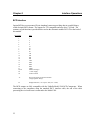
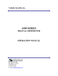
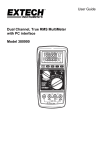
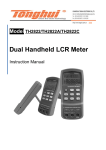
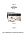
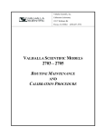
Valhalla Scientific, Inc.
MODEL 4021
DIGITAL OHMMETER
OPERATION MANUAL
8318 Miramar Mall
San Diego, CA 92121
P: 858/457-5576
F: 858/457-0127
W: www.valhallascientific.com
VALHALLA SCIENTIFIC INC. CERTIFICATION
Valhalla Scientific, Inc. certifies that this instrument was thoroughly tested and inspected and found to
meet published specifications when shipped from the factory. Valhalla Scientific, Inc. further certifies
that its calibration measurements are traceable to the Nation Institute of Standards and Technology to
the extent allowed by NIST’s calibration facility.
Due to continuing product refinement and due to possible parts manufacturer changes, Valhalla
Scientific, Inc. reserves the rights to change any or all specifications without notice.
VALHALLA SCIENTIFIC INC. WARRANTY STATEMENT
The warranty period for this instrument is stated on your invoice and packing list. Please refer to these
to determine appropriate warranty dates.
We will repair the instrument during the warranty period provided it is returned to Valhalla Scientific,
Inc. freight prepaid. No other warranty is expressed or implied.
Valhalla Scientific, Inc. is not liable for consequential damages.
Permission and a Return Material Authorization number (RMA) must be obtained directly from the
factory for warranty repairs. No liability will be accepted if returned without such permission.
Due to continuing product refinement and due to possible parts manufacturer change, Valhalla
Scientific reserves the right to change any or all specifications without notice.
4021 Digital Ohmmeter User Manual
Edition 1
Copyright © 2003 Valhalla Scientific, Inc. All rights reserved
2
Documentation History
All Editions and Updates of this manual and their creation date are listed below. The first Edition of
the manual is 1. The Edition Number increments by 1 whenever the manual is revised. Updates,
which are issued between Editions, contain replacement pages to correct or add additional information
to the current Edition of the manual. Whenever a new Edition is created, it will contain all of the
Update information for the previous Edition. Each new Edition or Update also includes a revised copy
of this documentation history page.
Edition 1 ………………………………………………….April, 2003
Update 1 ………………………………………….....September, 2004 (Board Rev. B)
Safety Symbols
Instruction manual symbol
affixed to product.
Indicates that the user must
refer to the user manual for
specific WARNING or
CAUTION information to
avoid personal injury or
damage to the product
Alternating current (AC)
WARNING, RISK OF
ELECTRICAL SHOCK.
Direct current (DC)
Indicates the field wiring
terminal that must be
connected to ground before
operation the equipment --protects against electrical
shock in case of fault.
Frame or chassis ground
terminal --- typically
connects to the equipment’s
metal frame.
3
WARNING
Calls attention to a procedure,
practice, or condition that could
cause bodily injury or death.
CAUTION
Calls attention to a procedure,
practice, or condition that could
possibly cause damage to
equipment or permanent lost of
data.
WARNINGS
The following general safety precautions must be observed during all phases of operation, service, and
repair of this product. Failure to comply with these precautions or with specific warnings elsewhere in this
manual violates safety standards of design, manufacture, and intended use of the product. Valhalla
Scientific assumes no liability for the customer’s failure to comply with these requirements.
Ground the equipment: For Safety class 1 equipment (equipment having a protective earth terminal), an
interrupted safety earth ground must be provided from the main power source to the product input wiring
terminals or supplied power cable.
DO NOT operate the product in an explosive atmosphere or in presence of flammable gases or fumes.
For continued protection, replace the line fuse(s) only with fuse(s) of the same voltage and current rating
and type. DO NOT use repaired fuses or short-circuited fuse holders.
Keep away from live circuits: Operating personnel must not remove equipment covers or shields.
Procedures involving the removal of covers or shields are for use service trained personnel only. Under
certain conditions, dangerous voltage may exist even with the equipment switched off. To avoid dangerous
electrical shock, DO NOT perform procedures involving cover or shield removal unless you are qualified
to do so.
DO NOT operate damaged equipment: Whenever it is possible that the safety protection features built
into this product have been impaired, either through physical damage, excessive moisture, or any reason,
REMOVE POWER and do not use the product until safe operation can be verified by service-trained
personnel. If necessary, return the product to Valhalla Scientific for service and repair to ensure that safety
features are maintained.
DO NOT service or adjust alone: Do not attempt internal service or adjustment unless another person,
capable of rendering first aid and resuscitation, is present.
DO NOT substitute parts or modify equipment: Because of the danger of introducing additional
hazards, do not install substitute parts or perform any unauthorized modification to the product. Return the
product to Valhalla Scientific for service and repair to ensure that safety features are maintained.
Measuring high voltage is always hazardous: ALL multimeters input terminals (both front and rear)
must be considered hazardous whenever inputs greater than 42V (dc or peak) are connected to ANY input
terminal.
Permanent wiring of hazardous voltage or sources capable of delivering grater than 150VA should be
labeled, fused, or in some other way protected against accidental bridging or equipment failure.
DO NOT leave measurement terminals energized when not in use.
4
Contents
Safety Symbols
WARNINGS
3
4
Circuit Descriptions
Power Supplies
Constant Current Source
18
18
19
Chapter 1 General Information
Introduction
Manual Description
Instrument Description
Safety Considerations
Instrument Identification
6
6
7
7
7
Transconductance Amplifier
Analog to Digital Converter
LED Display
20
20
21
Chapter 7 Routine Maintenance
General
Required Test Equipment
Calibration Procedure
Battery Replacement Instructions
22
22
23
24
Chapter 8 Interface Operations
BCD Output
25
Chapter 9 Addendums
Addendums
26
Chapter 10 Parts List
Main Board Assembly
Display Board Assembly
Chassis & Final Assembly
Option BCD Assembly
28
30
31
32
Chapter 2 Unpacking and Installing
Inspection
8
Power Requirements
8
Installation
8
Chapter 3 Specifications
Range / Resolution / Test Current
Accuracy
Temperature
General Specifications
Power Specifications
Physical Specifications
10
10
10
10
11
11
Chapter 4 Optional Equipment
Available Options
Test Leads
Interface
12
12
13
Chapter 5 Operations
General
Front Panel
Rear Panel
4-Wire Resistance Measurements
Connections
Interpreting the Display
14
14
14
15
16
16
Chapter 6 Theory of Operation
General
Troubleshooting
17
17
5
Chapter 11 Schematics & Drawings
33
4021-070 1 of 4
a
4021-070 2 of 4
b
4021-070 3 of 4
c
4021-070 4 of 4
d
4021-071 1 of 1
e
2053-76
f
4021-080 1 of 1
g
4021-700 1 of 1
h
4021-701 1 of 1
i
Chapter 1
General Information
Introduction
This manual has information to perform Inspection, Installation, Measurement Operations, and
Troubleshooting for Valhalla Scientific Model 4021. Also included in this manual are:
Specifications, Parts Lists and all Schematics.
Manual Description
This manual is separated into the 11 following Chapters.
Chapter 1 – General Information
Chapter 1 contains a brief description of the
instrument and other general information.
Chapter 2 – Unpacking and Installing
Chapter 2 contains information for unpacking
and inspection the equipment. Also contains
power requirements and installation procedure.
Chapter 3 - Specifications
Chapter 3 contains all specifications, including
Range, Resolution, Test Current, Accuracy,
General and Physical Specifications for Valhalla
Model 4021.
Chapter 4 – Optional Equipment
Chapter 4 contains information on all available
options and test leads for the Valhalla Model
4021.
Chapter 5 – Operations
Chapter 5 describes all operations including a
description of the front and rear panel,
Measurements and Connections.
Chapter 6 – Theory of Operation
Chapter 6 describes the theory of operation of all
circuits and sub circuits used on Valhalla Model
4021.
Chapter 7 – Routine Maintenance
Chapter 7 contains maintenance information,
such as calibration procedure.
Chapter 8 – Interface Operation
Chapter 8 contains information on the optional
BCD Output.
Chapter 9 – Addendums
Chapter 9 lists updates and addendums for this
manual.
Chapter 10 – Parts List
Chapter 10 contains all parts used in the Main
Board, Display Board, and Chassis of the
Valhalla Model 4021. The parts are listed with a
Reference Designator, Valhalla Part Number,
Description, and Manufacturers Part Number.
Chapter 11 – Schematics
Chapter 11 contains all schematics and drawings
for Valhalla Model 4021.
6
Instrument Description
Inspired by the need for a low-cost solution to the problems inherent in low resistance
measurements in the millennium, Valhalla Scientific developed the Model 4021 Digital
Ohmmeter. The 4021 uses a true "four-wire Kelvin" configuration in order to provide an accurate
resistance measurement down to 1 milliohm resolution. The wide range of the 4021 allows
measurement up to 1.9999 MΩ. Four-wire resistance measurement is explained in more detail in
Chapter 5.
The 4021 is available with a variety of test probes, accessories, and a BCD data output (see
Chapter 8). The 4021 is also capable of being operated from an internal heavy-duty battery pack
(optional). These items are explained in more detail in Chapter 4.
Safety Considerations
The Model 4021 is a very safe and easy to use device. Several items, however, are worth
mentioning in order to obtain maximum utility and safety from your instrument.
1) For AC instruments always use the three-terminal power cord provided or its exact
equivalent. The 4021 requires a continuous ground connection for proper operation. If using
an extension cord, ensure the ground connection is continuous throughout the extension.
2) For battery-operated instruments, use only the adapter provided or its exact equivalent. The
batteries may be damaged by excessive charging currents.
3) The fuses for both AC and battery operated instruments are for the safety of the user as well
as the instrument. Always replace blown fuses with their exact equivalent only!
4) If testing large inductive devices such as transformers, avoid drawing an arc when connecting
or disconnecting the leads. This is best accomplished by selecting the highest resistance
range (2MΩ) before making or removing connections.
Instrument Identification
Valhalla Scientific instruments are identified by a two part serial number. The Serial Tag is
located on the rear or bottom of the instrument. The number is in a form of 00-0000. The first
two digits, called the serial number prefix, indicate the model. It changes only when a change is
made to the instrument. The last 3 or 4 digits, called the serial number suffix, are unique for each
individual unit.
Be sure to include the entire serial number, both prefix and suffix, in any correspondence about
your instrument.
The serial number can also be found on the Main Board, Calibration Tag and Certificate of
Calibration.
7
Chapter 2
Unpacking and Installing
Inspection
If the shipping carton is damaged, request that the carrier's agent be present when the unit is
unpacked. If the instrument appears damaged, the carrier's agent should authorize repairs before
the unit is returned to the factory. Even if the instrument appears undamaged, it may have
suffered internal damage in transit that may not be evident until the unit is operated or tested to
verify conformance with its specifications. If the unit fails to operate or fails to meet the
performance specifications of Chapter 3, notify the carrier's agent and the nearest Valhalla Sales
Office. Retain the shipping carton for the carrier's inspection. DO NOT return equipment to
Valhalla Scientific or any of its sales offices prior to obtaining authorization to do so.
Power Requirements
The standard Model 4021 is fitted for operation from an AC power source such as municipal AC
line power. It may also be modified for operation from an internal rechargeable battery pack.
Battery operation is indicated by the lack of an AC power cord receptacle on the rear of the
instrument.
For AC operation, the 4021 is shipped from the factory for operation at either 115VAC or
230VAC, 50 to 400 Hz. This voltage range is preset at the factory and should be specified when
placing the order. All units are wired for 115VAC unless otherwise noted. When 115VAC is
selected, the unit will operate at line voltages of 105 to 125 volts. If 230VAC is indicated, the
unit will operate at line voltages of 210 to 250 volts.
The rear panel line fuse value is 0.1A Slo-blo.
Battery operation is indicated by the presence of a battery charging jack on the rear panel of the
instrument. In this case, the 4021 uses four (4) rechargeable nickel-cadmium batteries as its
source of power. A battery charger is supplied with the 4021. The 4021 may be operated from
the batteries for approximately 12 hours before requiring a recharge. The 4021 may also be
operated directly from the charger if desired, or if batteries have become depleted. Use only the
charging adapter provided or its equivalent to avoid internal damage. The line fuse installed for
battery operation is a 2 amp Fast-blo fuse.
Note: As a rule of thumb, the instrument requires twice as much time to recharge as the time it
was in operation. (i.e. 4 hrs. charge for 2 hrs. use)
Installation
If the Model 4021 is to be used in the bench-top configuration, installation requires only that the
line cord be connected to the rear panel connector and the other end inserted into the appropriate
wall receptacle. A rear- panel mounted fuse provides protection for the internal circuits.
8
If the unit is to be installed in a rack, assemble the ohmmeter into the rack mount adapter (Option
R4) using the instructions included with the option. Then it is only necessary to locate the unit in
the rack and make the power source and test lead connections.
The unit should be operated only in areas where the ambient temperature does not exceed 50°C.
If the internal temperature of the rack system in which the unit is installed will exceed this temperature limit, forced air cooling should be employed to maintain the ambient air at or below the
50°C limit.
9
Chapter 3
Specifications
This section lists the operating and accuracy specifications for Valhalla Scientific Model 4021
Digital Ohmmeter. Accuracy is valid at 25°C ± 5°C for a period of one year from the date of
calibration.
Range/Resolution/Test Current/Accuracy
Table 1
Range
Resolution
Maximum
Input
Nominal
Test Current
Accuracy
20Ω
1mΩ
19.999Ω
10mA
±0.05% of rdg, ±0.025% of rng
200Ω
10mΩ
199.99Ω
1mA
±0.05% of rdg, ±0.025% of rng
2kΩ
100mΩ
1.9999kΩ
100µA
±0.05% of rdg, ±0.025% of rng
20kΩ
1Ω
19.999kΩ
10µA
±0.05% of rdg, ±0.025% of rng
200kΩ
10Ω
199.99kΩ
1µA
±0.07% of rdg, ±0.03% of rng
2MΩ
100Ω
1.9999MΩ
100nA
±0.1% of rdg, ±0.15% of rng
Temperature
Temperature Coefficient:
±0.002% per °C (from 0°C-15°C and 35°C-50°C)
not applicable for 200kΩ range and above.
Operating Temperature Range:
0°C to 50°C
Storage Temperature Range:
-10°C to 70°C
General Specifications
Full Scale Test Voltage:
200mV
Current Source Compliance Voltage:
5V
Terminal Configuration:
4-Wire
Display Type:
4 ½ Digit LED’s
Overrange/Overload Indication:
Display Flashes
Conversion Rate:
3 readings/seconds
10
Power Specifications
Power Source (Standard AC):
115 or 230 VAC, ±10%, 50Hz – 400Hz
Power Source (Optional DC):
4 rechargeable Ni-Cad Batteries 1.2V 4000mA/H
Battery Charger (Standard with DC)
Provides 6VDC at 300mA nominal
Physical Specifications
Width:
9.5” / 24cm
Depth:
11” / 27cm
Height:
3” / 8cm
Weight (AC Power):
3 lbs / 1.5kg net; 5 lbs / 2.5kg shipping [1]
Weight (DC Power):
4 lbs / 2kg net; 8 lbs / 4 kg shipping [1]
[1] Shipping weight may vary.
11
Chapter 4
Optional Equipment
Available Options
Listed below are the options available for use with the Model 4021 Digital Ohmmeter.
Option CC4: Carrying Case
Option "CC4" is a meter and accessory carrying case with extra room for test leads,
power cord, etc.
Option HDB: Battery Operation
The 4021 may be modified at the factory for operation from an internal rechargeable
battery pack. This option was described in Chapter 2.
Replacement batteries for Option HDB are available as Valhalla Stock № 05-10117
quantity: 4.
Option A: Battery Charger
Option "A" is an AC to DC converter that is used to convert 115VAC line voltage into
6VDC @300mA which is required to recharge the batteries of a 4021 fitted with Option
HDB. One Option "A" is provided if the 4021 has been fitted with Option "HDB".
Additional adapters may be ordered as needed.
Option R4: Rack Mount Adapter
Option "R4" is an adapter tray that allows the Model 4021 to be installed in a standard
19" equipment rack.
Test Leads
Option K: 4-Wire Kelvin Lead Set
Option "K" is the recommended general purpose lead set for all Valhalla Ohmmeters.
Option K is a shielded 48" lead set terminating in ½ inch gold plated clips.
Option MP-S: Single Probe Lead Set
Option "MP-S" is a 4-wire lead set terminated in single points. The 4-wire configuration
is maintained up to the point of the probe, eliminating most cable resistance effects.
Option MP-S may be used where a single probe tip is a must.
Option MP-1: Kelvin Micro-Probes
Option "MP-1" is a 48" shielded lead set (dual banana), handheld pencil type, terminated
in spring loaded steel tips with .05" separation (1 amp max.). Special orders or modified
versions available upon request.
12
Option MP-2: Kelvin Mini-Probes
Option "MP-2" is a 48"shielded lead set, handheld pencil type, terminated in spring
loaded steel tips with 0.18" separation. (1 Amp max.)
Option MP-3: Kelvin Micro-Probes
Option "MP-1" is a 48" shielded lead set (dual banana), handheld pencil type, terminated
in spring loaded steel tips with .08" separation (1 amp max.). Special orders or modified
versions available upon request.
Option MP-4/MP-5: Surface Probes
These probes permit rapid, repeatable bonding testing on a variety of screened or flat
surfaces. Test current is evenly distributed through the probe base while sensing is
accomplished via a spring loaded center contact. The "MP-4" target area is 1" in
diameter. The "MP-5" target area is .4" in diameter.
Option KK: 4-Wire Kelvin Lead Set
Option "KK" is a 48" heavy duty cable set terminated in large "jaws" that have an open
span of 2".
Option C: Banana-to-Clip Cable
Option "C" is a 48" shielded cable terminated in dual alligator clips
Option BBL: Banana-to-Banana Cable
Option "BBL" is a 48" shielded cable terminated in dual banana plugs at both ends.
Option KCS: Kelvin Clips
Option "KCS" is the gold plated Kelvin clips used on the Option "K" cable. These clips
may be used when making custom cables or when repairing Option "K".
Option JAWS: Heavy-Duty Clips
2" opening for use on large bushings, transformers and motors. The upper/lower jaw teeth
(gold plated) provide true 4-wire measurement. Can accommodate up to 150 amps.
Interface
Option BCD: Data Output
This option provides parallel BCD data on p rear-panel 50-pin connector. All outputs are
TTL comparable levels with a drive capability of 1 LS load. The Option BCD may be
used to drive the Valhalla Model 1248. (See Chapter 8)
Model 1248: Dual-Limit Comparator
The Valhalla Model 1248 may be used in conjunction with a 4021 and Option BCD above.
The Model 1248 is a dual-limit BCD comparator that interprets the display indications of
the ohmmeter as either "HI", "LO" or "GO", based on a tolerance that is set by the user.
Relay contact closure is provided to trigger an alarm, counter, batch sorter or other device.
The 1248 also reduces operator workload by allowing him to make an instant determination
of the test results. The mating cable from the ohmmeter to the 1248 is 3' in length and
designated as "IDC-2".
13
Chapter 5
Operations
General
This section of the manual contains complete operating instructions for the Valhalla Model 4021
Digital Ohmmeter. A description of the front panel controls, connection instructions, and the
theory behind 4-wire resistance measurement is discussed in this section.
Front Panel
Power Switch
Power is applied to or removed from the internal circuits of the 4021 by this switch. On battery
operated units, this switch does not need to be turned OFF in order to charge the batteries.
Range Switch
The Model 4021 input range is selected by depressing the desired button on a multi-station
interlocking push-button array located on the right-hand side of the front panel. The push-button
for the lowest resistance range is nearest to the POWER switch. The value of the range is
indicated above the respective button.
Rear Panel
Fuse holder
The fuse-holder is mounted on the rear panel and is designed to protect the internal circuitry. For
AC units, this fuse is a 0.1 Amp Slo-blo fuse. In battery operated units, this fuse is used to
protect the battery pack from excessive charging currents and is a 2 Amp fast-blo fuse. Replace
blown fuses with the same type and rating only!
AC Receptacle
The standard AC receptacle is a three-contact type where the third contact provides a protective
ground. Use the mating power cord provided or its exact equivalent.
Charging Jack
For battery operated units, the battery charging jack is a barrel type and is located on the rear
panel. The center pin of the connector is positive (+). The charging requirements of the internal
battery pack are 6VDC @300mA. The correct charging voltage is supplied by the adapter
included with the instrument. Additional adapters are available as Option "A".
14
4-Wire Resistance Measurement
The four-terminal configuration of the 4021 eliminates errors normally caused by test lead and
contact resistances. In many applications the contact resistance can exceed the value of the load
by several orders of magnitude. The 4021 bypasses this potential error source by providing two
terminals of constant current and an additional two terminals for high impedance voltage
measurement. The result is a fast, accurate resistance measurement of the load, independent of
the resistance of the current carrying leads.
Figure 1 Error Sources in Resistance Measurements
Figure 1 illustrates how the 4-wire principle is used to eliminate lead, wire and contact
resistances as potential error sources. The internal current source inherently overcomes all series
resistance (within compliance voltage limits) and delivers a precise constant current.
The internal high-impedance DVM senses the voltage drop across the load. There is negligible
contact and lead resistance error created by the voltage measurement because the high input
impedance of the DVM limits current flow in the voltage leads.
15
Connections
Connections are made to the front panel terminals using a 4-wire configuration as described in 4Wire Resistance Measurement. When using Valhalla test leads, the tabbed side of the banana
jack is plugged into the current terminals. This ensures that the current is carried in the largest
conductor and that the voltage input is shielded.
VHI ☼
☼ IHI ←Tab
VLO ☼
☼ ILO ←Tab
Interpreting the Display
All Valhalla ohmmeters use a high impedance voltmeter as part of the resistance measurement
process. This voltmeter is a highly accurate and stable 4 ½ digit analog-to-digital converter (A to
D). Unless it is receiving a definite input signal, the output reading of this A to D is ambiguous.
The display may indicate a randomly wandering number or it may indicate an overrange
condition. This unpredictable display may make it seem to appear that the instrument is
experiencing some sort of malfunction. It is, in fact, just a characteristic of the voltmeter circuit
and should not be mistaken for a fault in the instrument.
The display indications should be ignored unless there is a definite measurement being taken. If
this wandering display is not acceptable, the ohmmeter can be made to indicate an overrange
condition whenever the terminals are open by using a 4-wire Kelvin type lead set or by shorting
the VHI and IHI terminals together.
The display should indicate a stable reading when the test leads are securely attached to the
device under test. If the display appears to be erroneous when connected to a load, recheck the
test leads for integrity and cleanliness. If all external items appear to be functioning properly, the
problem may be the ohmmeter. In this case, please contact your local Valhalla Scientific Sales
Office.
16
Chapter 6
Theory of Operations
General
The Valhalla Scientific Model 4021 Digital Ohmmeter is shown in block diagram form in Figure 2.
All information disclosed in this section is proprietary and is included in order to make
troubleshooting to component level possible.
The Model 4021 uses solid-state semiconductors exclusively and CMOS circuits extensively to
minimize power requirements and make battery operation practical.
Current
Source
Range
Switch
120 kHz
Oscillator
A/D
Converter
Load
Display
Driver
Amp.
DC
Reference
Led
Display
Figure 2 Model 4021 Block Diagram
Troubleshooting
Malfunctions are often the result of misinterpretation of specifications or due to an incomplete
understanding of the instrument. A thorough review of the operating instructions for this
instrument is recommended prior to any component replacement. Check to be sure that cables
and other test equipment are in good working order before attempting to troubleshoot the 4021.
If the Model 4021 exhibits problems that cannot be eliminated by reviewing Chapter 3 and 5, the
following guidelines have been established to help solve the problem.
17
Localizing the Problem:
The key to successful troubleshooting is to localize the problem as much as possible before trying to
pin the problem down to a specific component. Certain questions should be asked such as "Does
the problem occur on all ranges or on a specific range only?” The power supplies are also one of
the first things that should be checked.
As it is not possible to anticipate all failure modes of the 4021, servicing personnel should become
familiar with this section to gain a complete understanding of the internal workings of the Model
4021.
Component Replacement
If the problem has been identified as a faulty component, the accuracy of the 4021 can be
maintained only if the following precautions are taken:
a) Use only the specified component or its exact equivalent. Spare parts can be ordered
from your nearest Valhalla Scientific Service Center or directly from the factory by
referring to the Valhalla Stock Number listed in the Parts Lists section at the back of this
manual.
b) Use only 63/37 grade rosin core electronic grade solder with a 50W or lower maximum
power soldering iron.
c) When soldering, heat the terminal of the component, not the solder. Apply solder
smoothly and evenly. Do not move the component until the solder has cooled. Bad
solder joints can cause additional problems!
d) Static sensitive parts require special handling procedures. Always treat an unknown part
as if it were static sensitive.
Circuit Description
The circuit descriptions which follow are referenced to Figures 2, 3, 4 and the schematic
diagrams in Chapter 11. In the following descriptions, references to integrated circuits are given
in the form "IC2-1", which refers to Integrated Circuit 2, pin 1.
Power Supply
The 4021 operates from 4 supplies: +5V, +5Vb, -5V and -10V. The +5V supply is rectified by
D1 and D2 and regulated by IC1 in AC units. The +5V supply is provided directly by the
batteries in DC units. The other power supplies are identical in either AC or DC units.
The -10V supply is the result of a DC-to-DC converter composed of Q1, Q2, T1, D5, D6 and
associated components.
18
The -5V supply is regulated by IC2 from the -10V supply mentioned above.
The +5Vb supply is regulated by IC3 from a +10V resultant from the DC-to-DC converter
composed of Q1, Q2, T1, D8, D9 and associated components.
Constant Current Source
The constant current source is composed of IC4, IC5, Q4 and the precision resistor R26 and R28 –
R32. The input to the constant current source is approximately +1.05 volts, developed at IC4-7 and
connected to IC4-13 through R12 and R13.
The heart of the constant current source is the voltage-to-current converter, which incorporates a
Transconductance Amplifier. A simplified schematic of this unique circuit is shown in Figure 3 and
described in the next section. The amplifier of IC4-12 is an inverter, and its output is applied to
IC4-9. The amplifier of IC4-8 has unity gain due to the feedback through R18. Its output is applied
to the inverting input of IC5-3. The output of IC5-6 provides feedback to the non-inverting input of
IC4-10. This circuit operates to maintain the inverting input at IC5-3 and the non-inverting input at
IC5-2 at the same potential.
Figure 3 Transconductance Amplifier
19
Transconductance Amplifier
(U.S. Patent No. 4,091,333)
Assume that terminals Ihi and Ilo of Figure 3 are shorted, and 1 volt is applied to Ein so that Ihi is
positive. To equalize the inputs of IC5, IC4 must be driven to zero. This condition occurs only
when the voltage drops across R17 and R19 are equal to the drops across R18 and R20. For these
voltage drops to be equal, the output of IC5 must be at +1 volt. Since the output of IC4-8 must be
zero, the drop across R18 is 0.5 volts, making the inverting input 0.5 volts. The drops across R17,
R20 and R19 will also be 0.5 volts. Since the inputs to IC4 are essentially equal, its output is zero
(offset by the few µV required to drive IC5 to +1 volt). Under these conditions the sum of the
voltages across R17, R18, R19 and R20 equals the sum of Ein plus the output of IC5.
Consider now that the short is removed from the Ihi and Ilo terminals and a 100-ohm resistor (RL) is
connected in its place. The current through RL increases the voltage at the input to IC4. A balanced
condition will be reached when the output of IC4 is equal to the non-inverting input of IC5. Again,
this condition occurs when the voltage drops across R17 and R19 are equal to the voltage drops
across R18 and R20. At this time the output of IC5 is 1.1 volts. The voltage drop across the Range
Resistor is 1 volt, just as it was when the output terminals were shorted. The current through RL is
10mA, just as it was through the jumper when the output terminals were shorted.
Analog to Digital Converter
The Analog to Digital conversion in the Model 4021 is aloud by IC 7 and its associated
components. The reference voltage applied to IC7-2 is 1Volts. 1.2Volts are generated buy D16
and adjusted by R40 before being applied to IC7-1. Due to this reference, the voltage across the
load is amplified X10 by IC6 and its associated components. IC8 generates a 120 kHz clock
signal for IC7-22; the frequency of the oscillator allows the 4021 a conversion rate of 3 readings
per second.
The digital portion of IC7 is applied to IC9 a BCD to 7 Segment Converter/Driver and to the
driver transistors Q5-Q9.
20
LED Display
The signal converted by IC9 is applied to four 7 Segment LEDs (DS2-DS5) and a ±1 LED (DS1).
Concurrently, driver transistors Q5 through Q9 are turned on in sequence. This sequence is repeated
at the 120 kHz rate, and the data display consequently appears to be continuous.
Figure 4 LED Display Pin Function
21
Chapter 7
Routine Maintenance
General
This section of the manual contains routine maintenance information regarding the Valhalla
Scientific Model 4021 Digital Ohmmeter. Calibration should be performed on a regular basis to
ensure continued instrument accuracy. The recommended calibration interval is 1 year.
Required Test Equipment
Following is a list of the standard resistors and other equipment required to calibrate the Model
4021.
Precision Resistors:
10Ω ± 0.005% Accuracy
100Ω ± 0.005% Accuracy
1KΩ ± 0.005% Accuracy
10KΩ ± 0.005% Accuracy
100KΩ ± 0.005% Accuracy
1MΩ ± 0.005% Accuracy
Test Leads:
4-Wire Lead Set
(Valhalla Option "K" or "C")
Voltage Standard:
Voltage Calibrator capable of outputting negative 100mV, 0.03% Accuracy or better.
(Valhalla Model 2701C)
22
Calibration Procedure
The 4021 should be allowed to warm-up for a minimum of 5 minutes before beginning the
procedure. The adjustments are accessed by removing the four feet screws, then lifting off the top
cover only. The locations of the adjustments are shown on drawing number 4021-700 in Chapter
11.
Voltmeter Adjustment
1.
2.
3.
4.
5.
6.
Select the 20Ω Range on the 4021.
Connect the Voltage Calibrator to the Sense terminal observing polarity.
Apply -100mV and adjust R40 for a display reading of “10.000” ± 1 digit.
Apply -100µV and adjust R37 for a display reading of “0.010”.
Repeat steps 3 and 4 until both are in specification.
Disconnect the Voltage Calibrator.
Full Scale Adjustment
1.
2.
3.
4.
5.
6.
Select the 20kΩ Range.
Connect the Kelvin clips to a 10Ω standard resistor.
Adjust R37 for a display reading of “0.010”.
Connect the Kelvin clips to a 10kΩ standard resistor.
Adjust R15 for a display reading equal to the resistor value.
Check all remaining ranges with the appropriate standard resistors. All ranges must
be within the specifications outlined in Chapter 3.
Note: The 2MΩ range uses just 100 nano-amps of test current to make the resistance
measurement. This amount of current can easily be disturbed by movement of people or
objects in the test area. When checking this range, keep movement to a minimum.
Note: When using the 2MΩ Range, allowe approximetly 30 seconds for the readings to
stabilize.
End of procedure. #
23
Battery Replacement Instructions (For DC powered instruments only)
The rechargeable NiCad batteries used in the 4021 are very durable and should provide years of
trouble-free operation. As with all batteries, replacement will eventually be necessary. Batteries
may be ordered from Valhalla Scientific as stock #05-10117, quantity: (4).
The process of battery replacement is described below:
1.
2.
3.
4.
5.
Remove the four feet screws and the bottom cover.
Undo the reusable tie-wraps by pushing down on the locking pin.
Remove the old batteries and replace. Observe polarity!
Secure the new batteries in place by re-tightening the tie-wraps.
Replace the cover and feet screws, taking care not to pinch any wires.
24
Chapter 8
Interface Operations
BCD Interface
Option BCD has a rear mounted 50 pin Amphenol connector providing data in a parallel binarycoded-decimal (BCD) format. The outputs are TTL compatible and may drive 1 LS load. The
summary of pin functions is provided below and on the schematic number 2053-076 at the back of
this manual.
Pin Number
Data
1
2
3
4
6
7
8
9
11
12
13
14
16
17
18
19
21
22, 40
26
50
1
2
4
8
10
20
40
80
100
200
400
800
1000
2000
4000
8000
10000
20000 (overrange)
+5 VDC supply
0 VDC common
35
End of Conversion on negative transition
(A high signifies "Busy")
45
Display Hold Line (+5V or open = Run; 0V = Hold)
The BCD outputs are fully compatible with the Valhalla Model 1248 BCD Comparator. When
connecting to the comparator using the standard IDC-2 interface cable, the end of the cable
possessing the wire break-outs is connected to the Model 1248.
25