1
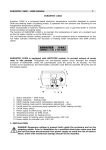
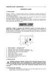
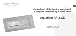
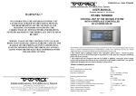
EUROSTER 1100/1100C – USER MANUAL
1
EUROSTER 1100/1100C
Congratulations on choosing our thermostatic controller EUROSTER. It is a technically
advanced product which will serve you and your family for years bringing energy savings and
thermal comfort.
Prior to operating our thermostatic controller, please read this manual carefully.
1. FUNCTION
Euroster 1100 and Euroster 1100C are electronic thermostatic controllers controlling the
operation of circulation pumps in hydronic heating systems, according to the temperature
settings.
The function of the thermostatic controller/pump assembly is to cause forced circulation of
water in hydronic heating systems supplied by coal or gas-fired boiler(s), which are not
equipped with a pump control unit. The sensor of the thermostatic controller measures the
heating water temperature on the inlet to the hydronic heating system.
In a hydronic heating system supplied by a coal-fired boiler the thermostatic controller will
switch off the pump upon flame failure. Pumping of water upon flame failure should be
avoided, as suction caused by chimney draft will result in quicker lowering the temperature of
water inside the boiler as compared to the radiators. The optimum temperature is preset on
the controller’s scale (40ºC is the most common setting).
In a hydronic heating systems supplied by a gas-fired boiler the temperature preset on the
Euroster 1100/ 1100C must be lower than the temperature setting on the thermostatic
controller fitted on the boiler. In order to avoid condensation on the surface of boiler during
heating-up (so-called “sweating”) the temperature set with the knob should be above the dew
point.
EUROSTER 1100 C is equipped with ANTISTOP system, to prevent seizure of pump rotor in idle
periods. Throughout the non-heating season every fortnight the integral processor of
EUROSTER 1100 C will automatically cycle the pump for 30 seconds. For this function to be
operational, the thermostatic controller must NOT be switched off at the end of the heating
season.
1.
2.
3.
4.
5.
6.
7.
8.
Power indication
Pump status indication
Power switch
Continuous operation switch
Temperature adjustment
230 V power supply cable
Pump output cable
Temperature sensor
EUROSTER 1100/1100C – USER MANUAL
2
2. INSTALLATION
a) mounting of the thermostatic controller:
− the thermostatic controller is mounted directly to wall or on a bracket with two screws
(expansion plugs c/w screws are part of delivery)
− for fixing the outgoing cables to the wall use cable clips
b) mounting of the temperature sensor:
− the sensor is not intended for immersion in liquids or installation in breechings/ flues
− the temperature sensor should be installed on a bare outlet pipe from the boiler (as
close to the boiler as possible)
− for securing the sensor on the pipe use the supplied fixing clip
− as a recommendation, the outlet pipe should be provided with thermal insulation on the
section between the boiler and the temperature sensor
IMPORTANT:
If a central heating system is supplied from two sources: a coal-fired boiler and a gas-fired
boiler, the temperature sensor should be mounted at the meeting point of the two outlet pipes
and insulated.
c) connection of power supply cable to terminals:
− terminal (
) - yellow or yellow and green (protective) conductor
− terminal (N) - blue conductor
− terminal (L) - brown conductor
d) check-up of connections:
− make sure that the connections have been made correctly and tighten the cover of the
pump motor terminal box
e) connection of thermostatic controller:
− upon securing the cables against accidental pullout, connect the power supply cable
to a 230V/50Hz grounding socket!
IMPORTANT:
Euroster 1100/ 1100C should be installed in a place with ambient temperature not exceeding
40ºC.
Danger! Hazardous voltage is present inside the enclosure. Any tampering with the
unit may result in a life-threatening electrical injury!
3. OPERATION
After switching on the controller allow ca. 30 sec. for the controller to become fully
operational
a) switching on:
− move the toggle switch (~) to position I
− the green LED lights up.
b) operation in the automatic mode:
− move the right-hand toggle switch (►) to position 0
− the pump is turned on and off depending on the temperature preset on the knob
− the pump is turned on when the temperature measured by the sensor is higher than
the preset temperature and it is turned off when the temperature has dropped below
the setpoint.
EUROSTER 1100/1100C – USER MANUAL
3
c) continuous operation mode:
− move the toggle switches (~) and (◄) to position I (both green LED and red LED are
on)
− the pump is running continuously irrespective of the setpoint and the ambient
temperature measured by the sensor.
4. DATA SHEET
a.
b.
c.
d.
temperature setting range
25ºC – 55ºC
hysteresis (turn on / turn off difference) ca. 5ºC
supply voltage
230V AC
rating of contacts
6A AC
5. SHIPPING LIST
a)
b)
c)
d)
e)
controller and sensor
fixing clip
wall plugs
user manual
installation template
1
1
2
1
1
No.
No.
No.
No.
No.
WIRING EXAMPLE
It is a simplified diagram and does not show all the components necessary for fully functional
operation of the system.
Legend:
1. gas-fired heating boiler
2. coal-fired heating boiler
2. shutoff valve
3. strainer
4. heating water circulating pump
5. check valve
6. heating unit – radiator
7. temperature sensor
8. central heating controller
EUROSTER 1100/1100C – USER MANUAL
4
Our products have been tested by the following certification bodies:
*ELTEST - Centre for Evaluation, Research and Development of Electronic and Electrical
Equipment – for conformity with the EMC Directive No. 89/336/EEC.
Certified for compliance with the requirements of the following harmonised standards:
PN-EN 60730-1:2002, PN-EN 60730-2-9:2000(U)
PN-EN 55022:2000
PN-EN 61000-4-2:1999+A2:2002(U)
PN-EN 61000-4-3:2002
PN-EN 61000-4-4:1999+A1:2001
PN-EN 61000-4-5-1998+A1:2002(U)
PN-EN 61000-4-6:1999+A1:2002
PN-EN 61000-4-11:1997+A1:2002(U)
*BBJ-SEP – Quality Testing Office – for compliance with the requirements of harmonised
standards for the Low Voltage Directive (LVD) No. 73/23/EWG+93/68/EWG.
Certified for compliance with the safety requirements of the following standards:
PN-EN 60730-1:2002
PN-EN 60730-2-9:2002