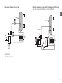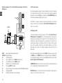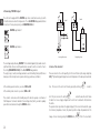
1
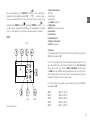
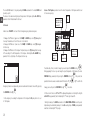
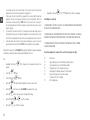
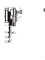
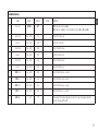
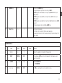
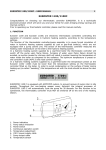
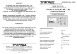
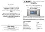
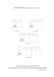
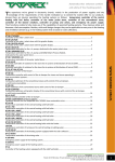
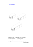
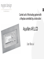
En
Control unit of the heating system with
a fireplace controlled by a choke valve
Aquaflam AFLLCD
User Manual
En
The RT-08G control unit controls the heating system based on the water jacket fireplace that is a heat
source, in which combustion process is controlled by a choke valve. The heat receivers are: Warm
Applicable Water accumulator (WAW) and Central Heating system (CH).
! The control unit is equipped with its own emergency power source - breaks in power supplying
up to 8 secs do not interrupt its operation (over the time the emergency buffering power source is
activated).
! The control unit can cooperate with the TATAREK A 200WAC emergency power supply system
which ensures that all the devices connected to the RT08G control unit can operate without any
disruption in case of power decline even up to 9 hrs.
1. Basic technical parameters
Power
Power consumption without load Max connection power
Operation conditions
Housing protection class
Fuse
Number of outputs to control pumps
Number of nonvoltage outputs Number of outputs to control the choke valve drive
Number of water temperature sensors
Temp. measurement precision
Temp. measurement resolution
Number of the time zones
20
230 V/50 Hz
5 W
750 W
0 – 50 °C, humidity 10 – 90%
(no condensation)
IP41
6,3A/250 V
3× 250 W/230 V/50 Hz
1 × max. 500 W
1 × 5 V/500 mA/DC
3 × KTY81 (0… + 100 °C)
2 °C
0,5 °C
4
2. Principle of Operation
The main function of the control unit is to keep temperature in the water jacket at the preset value.
The task is realized by measuring temperature (T3) and controlling the cold air choke valve (PP)
properly. Fireplace operation temperature is defined by the <20> “FIREPLACE Temp.” parameter
(see PARAMETERS LEVEL 1). If the fireplace temperature (T3) is higher than the <20> “FIREPLACE
Temp.” parameter the choke valve is gradually shut off limiting air supply, and if the temperature
(T3) is lower than the <20> “FIREPLACE Temp.” parameter the choke valve is gradually opened up.
The second function is to control the WAW pump loading the warm applicable water accumulator
(WAW). The WAW (P1) pump operates if the fireplace temperature both exceeds the <31> “Switch-on Temp. of PUMPS” value and is higher than the WAW accumulator temperature (T2) by the
<44> “Delta Temp. of WAW” parameter (see PARAMETERS LEVEL 1).
The third function is to control the circulating pump (P3) of central heating system. The pump works
if the fireplace temperature exceeds the <31> “Switch-on Temp. of PUMPS” value. It’s possible
to activate the WAW priority function “PRIORITY” - see the description of operation modes of the
WAW accumulator - chapter 2.4 of the manual. The control unit is also equipped with the “CLOCK”
function to control the WAW priority and the fireplace operation temperature in selected times of
day.
! The fireplace can also be equipped with warm air distribution system based on the RT-03C ARO
control unit. The control unit measures temperature in the chamber of the fireplace air ventilator
and controls its rotation speed in manual or automatic mode.
Operation configuration of the control unit with the heat exchanger for the CH system
(pump of the heat exchanger and the CH system connected to the P3 output)
Basic operation configuration of the control unit
En
WAW
WAW
FIREPLACE
CH
CH
FIREPLACE
CH = Central Heating
WAW = Warm Applicable Water

21
Operation configuration of the control unit with the heat exchanger for the CH and
WAW systems
2.1 Choke valve operation
The choke valve regulates an air supply to the combustion chamber, which allows the temperature
of the fireplace water jacket to be kept at the preset value. The task is realized by comparing the
temperature of the water jacket (T3) and preset temperature (the <20>”FIREPLACE Temp.” parameter) and then by gradual opening/shutting the choke valve.
En
WAW
The shutdown of the regulator (caused e.g. by power decline) automatically causes thechoke
valve to be set at the rest position defined by the <50> ChokeV State OFF parameter (Default
setting is 0% - full shut-off).
FIREPLACE
2.2 CH pump operation
CH
WAW FIREPLACE CH
T1
T2
T3
P1
P2
P3
PP
22
Warm Applicable Water accumulator (boiler)
Water jacket fireplace
Central heating system
Upper temperature sensor of the WAW accumulator (option)
Lower temperature sensor of the WAW accumulator
Temperature sensor of the fireplace water jacket
Pump loading WAW from fireplace
Pump of the primary side of heat exchanger (it operates if P1 and P3 are activated)
Circulating pump CH
Electronically controlled choke valve of the fireplace
If the fireplace temperature exceeds the preset value of 45 °C (the <31> Switch-on Temp. of
PUMPS parameter) the CH pump (P3) turns on. The fireplace inputs with the water jacket optimally operate at water temperature in the range of 45 °C - 85 °C. Most producers don’t recommend using the water jacket fireplace below the so-called dew point. The operation in such
conditions leads to emitting a lot of condensate on the surface of the furnace. The effect originates
from too much cooling down combustion gas in the combustion chamber. As a result it has a
negative impact on the cleanness of the fireplace windowpane, efficiency and life-time of the
fireplace input.
During loading the warm applicable water accumulator WAW, the CH pump can operate cyclically
if the WAW mode is set to PRIORITY (Limitation of the heat amount flowing into the CH system).
The cyclical operation is based on turning on the pump for 45 secs and then turning off for 4mins
(the <32> Stoptime of CH PUMP parameter).
! ANTIFREEZE Function - The control unit protects the system from freezing, automatically turning
on the circulating pump if the measured temperature is below 4 °C.
!ANTISTOP Function - The control unit realizes the after season rundown of the pump by switching it on for 1 min if it doesn’t operate for a week.
2.3 WAW pump operation
The control unit controls as well the pump (P1) loading the warm applicable water accumulator
WAW. The loading pump can be turned on if water temperature in the fireplace is higher than the
preset threshold of 45 °C (the <31> Switch-on Temp. of PUMPS parameter) and higher than in
the WAW accumulator by 5 °C (the <44> Delta Temp. of WAW parameter).
2.4 WAW priority and the summer mode
OFF - The WAW loading pump turned off. Only the CH pump can run.
En
Dependent on the quantity of connected temperature sensors of the WAW accumulator or the
buffer there are the following ways of the pump operation:
SUMMER - Turning off the heating system in summer time (the CH pump doesn’t
operate). Fireplace only works in the preparation function of the WAW. or loading
function of the buffer only.
** Sensors T1 and T2 not connected. Loading the WAW accumulator at random. The WAW
loading pump turns on if water temperature in the fireplace jacket reaches the preset value or is
higher than 50 °C (the <42> Minimum temp. of WAW parameter).
ON - Standard operation (parallel operation of pumps) without favouring the
WAW circuit
* One of the sensors T1 or T2 connected. The WAW loading pump (P1) turns on if the temperature
of the WAW accumulator is lower than 50 °C. (the <42> Minimum temp.of WAW parameter) and turns off if the temperature is higher than 60 °C (the <41> Maximum temp. of WAW
parameter).
** Both of the sensors T1(low) and T2(up) connected. The loading starts when the temperature
sensor (T1) measures below 50 °C (the <42> Minimum temp.of WAW parameter) and ends when
the temperature sensor (T2) measures above 60 °C (the <41> Maximum temp. of WAW parameter).
The <46> Loading mode of WAW parameter should have the value 2, which means the operation of both of the sensors. The value 1 causes the operation to be made like at the temperature
sensor T2 only active - sensor T1 then doesn’t take part in the control but its measurements are
still shown !.
After the loading of the WAW accumulator ends the pump runs for 1min (the <45> Rundown
Time of WAW PUMP), which prevents the temperature in the water jacket from rising, especially
in summer time when the CH pump doesn’t operate.
PRIORITY - Faster reaching the readiness of the WAW accumulator by limiting
heat obtain by the heating system. The CH pump works cyclically. Turning off the
WAW pump after loading the accumulator causes the comeback of normal operation of the CH pump
CLOCK - beyond the time zones $1...$3 the pump operates like in the ON mode
and in the time zone like PRIORITY
SPECIAL - beyond the time zones $1...$3 the pump operates like in the ON mode
and in the time zone like PRIORITY. Additionally during loading the WAW accumulator the preset temperature of the water jacket is raised up to 65 °C.(the <43>
Loading temp. of WAW special parameter)).
!ANTISTOP Function - The control unit realizes the after season rundown of the pump by switching it on for 1 min if it doesn’t operate for a week.
23
2.5 Nonvoltage “CONTROL” output
En
The control unit is equipped with the CONTROL relay whose contacts can be used e.g. to switch
off another heat source when the fireplace works. The <12> CONTROL Relay parameter defines
the function of the relay more precisely. (see PARAMETERS LEVEL 3)
Control
Control
CONTROL relay turned off
Gas
furnace
CONTROL relay turned on
Connecting additional pump
The nonvoltage relay described as „CONTROL” in the schematic diagram (Fig.3) enables connecting different kinds of devices controlling another device we want to switch on or switch off acc.to
the settings (PARAMETERS LEVEL 3) of the <12> CONTROL Relay parameter.
The output, relay, is inactive (nonvoltage) and can be used for handling (turning on/off) devices
making use of the normally closed or opened contacts (e.g. gas furnaces, ventilation).
Turning off the gas furnace
3. Service of the control unit
There are elements on the control panel (fig. 2). In the turn-off state only the orange stanby state
LED „1“ lights and the graphic display shows current temperature of the water jacket and current
F1
. In order to
At the normally opened connection you connect COM and NO
At the normally closed connection you connect COM and NC
time. The turn-on of the control unit follows by pressing the button „3”
Those contacts can be also used for handling any electric device like a pump or electrovalve of
500W max power. You have to remember it‘s a nonvoltage contact, that is, you need to separately
power that connected device through the CONTROL contacts.
turn it off press once more the button„3”
and at the same time hold it down
for about 1sec. In case of supply voltage decline the control unit comes back to the state before
the decline.
The operation state is presented on the graphic display (2). The screens inform about the operation of devices, temperature of sensors; they make it possible to change the parameters etc..The
F1
change of screen is done by pressing the CHOOSE button „7“
24
. If this is the screen that is
OK
able to change a parameter, press the CONFIRM button „6“
.which causes blinking of
the parameter field to be changed. By pressing “+” (4)
or “-” (5)
one can alter its value.
If there are more parameter fields on the screen (e.g. setting the clock) then one will go among
OK
. By clicking the CONFIRM button „6“
one
them by pressing the CHOOSE button „7“
confirms the changes - the parameter field stops blinking. The changed parameter not confirmed
for 10 secs is not accepted by the control unit and it recalls a previous value of the parameter.
ON/OFF
ON/OFF
1. Control unit status diode: - alarm (red),
- standby (orange),
- operation (green),
- manual MAN (blinking green)
2. Graphic display
3. Button F1: switch-on/off power supply
4. Increase button
5. Decrease button
6. Confirmation button
7. Parameter selection button
8. Button F2 (for producer)
En
3.1 Time zones
! In the default settings the time zones are turned off. In order to activate them you need to set the
<14> Time zones parameter to ON.
The control unit is equipped with the clock, which enables the automatic change of the control
unit operation at different times of day. 24 hrs are divided into 5 time zones ($1, $2, $3, e4, e5)
and the single time when no zone is active that is ZONE 0 or BAZA (BASE). Each zone has a start
time FROM and an end time TO. The same start and end time means the zone isn’t active, which
doesn’t change the settings of the control unit. The time zones can overlap each other in that case
binding are the settings for the active zone of higher number.
In the control unit there’s a zones program. In order to activate it you need to set the <14> Time
zones parameter to ON.
CHOOSE
Fig. 2 Control panel view
CONFIRM
ZONE $1 ZONE $2 ZONE $3 ZONE $4
ZONE $5
FROM 6.00
FROM 14.00
FROM 20.00
FROM 23.00
FROM 8.00
TO 8.00
TO 17.30
TO 22.30
TO 5.00
TO 13.30
25
En
The zones $1...$3 relates to the pump loading the WAW accumulator in the mode CLOCK and
Special (see p.2.4)
The zones e4...e5 enable lowering the preset temperature of the fireplace by the <22> ECO Temp.
parameter at the limited demand for the heat.
3.2 Screens
Alarm screens “ALARM” is not seen till the following emergency situation takes place:
1. Damage of the T1 sensor (upper one of the WAW). The WAW temp. sensor (T1) damaged.text
shows up. The alarm doesn’t work if the sensor is not installed.
2. Damage of the T2 sensor (lower one of the WAW). The WAW temp. sensor (T2) damaged.
text shows up.
3. Damage of the T3 sensor of the fireplace. The Fplace temp. sensor (T3) damaged text shows up.
4. The exceeding of the limit temperature of the fireplace defined by the <21> ALARM Temp.
parameter. The too high temp. of the fireplace text shows up.
Screen of the fireplace operation shows the current temperature of the fireplace and the level
of choke valve opening.
Temperature of the
water jacket of the
fireplace (T3)
Time
zone
FIREPLACE
Choke valve
opening
Current
time
Preset
temperature
Operation mode
of the fireplace
It’s a stable state, that is, in order to change it you need to press the CHOOSE button „7”
During appearing this screen you can change the preset temperature of the fireplace (the <20>
OK
the preset temFIREPLACE Temp. parameter). After pressing the CONFIRM button „6“
Emergency situation is accompanied by a broken sound alarm that can be turned off by pressing
OK
the CONFIRM button (6)
! In the emergency of exceeding the temperature of the fireplace the CH pump turns on to cool
off the fireplace.
26
perature blinks whose value can be altered with the buttons “+” „4“
OK
once more.
changes you need to press the CONFIRM button„6“
or „5“ To confirm the
! At the economic time zones “e4” or “e5” the displayed temperature is corrected by the drop (the
<22> ECO Temp. parameter) that is indicated by the “-” minus sign instead of C..
! During the loading of the WAW accumulator in the WAW MODE=SPECIAL mode the preset
temperature gets automatically raised up to the <43> Loading temp. of WAW special parameter
value that is indicated by the “+” plus sign
If the manual mode is set (FIREPLACE MODE=MAN) (the green LED diode (1) ! blinks.) you can
manually control the choke valve- the “+” button (4) causes the opening of the choke valve (one
step 10%) and the “+” button (5) causes its closing.
There are the following operation modes of the fireplace:
MAN - Automatic control locked - only manual control of the choke valve is available
Green status diode (1) blinks.
OFF - Setting the choke valve to the rest position ( the <50> ChokeV State OFF
parameter).Green status diode (1) doesn’t light.
ON - The choke valve is automatically controlled to stabilize temperature of the water
jacket. Green status diode (1) does light.
AUTO - Full automatic burning cycle in the fireplace (firing up - operation - burning
F1
. Green
out). Automatic operation is controlled by pressing the button „3”
status diode (1) lights during the fireplace operation and goes out when the burnt-out state is detected.
At the end of the burning-out phase the choke valve sets to the rest position (0%,
full shut-off), which prevents a room from cooling off and protects the water attachment against freezing.
F1
Automatic operation is activated by pressing the “ON/OFF” button „3“
The choke valve is fully opened. In 2hrs the fireplace ought to heat itself and reach
the preset temperature stabilized by choke valve movements. From that moment
the temperature fall to the preset temperature by more than 10 oC (the <23>
FPLACE OFF Temp. parameter) existing for 30mins is treated as a burnout of the
fireplace. The control unit ends the operation cycle setting the choke valve to the
F1
once more starts
rest position. Pressing the “ON/OFF” button „3” F1
another operation cycle. Green status diode (1) lights during the fireplace operation
and goes out after recognizing the burnout state of the fireplace.
AUTO operation icon in waiting for the start of a new cycle (that is, before its start
or after its end.
AUTO operation icon during the cycle.
27
En
It’s a stable state, that is, in order to change it you need to press the CHOOSE button „7”.
En
Operation screen of the whole system
Temperature of the
water jacket of
the fireplace
WAW pump
doesn‘t run
Possible operation modes of the WAW accumulator are as follows (described above):
OFF/SUMMER/ON/PRIORITY/CLOCK/SPECIAL
MODE
T1, T2 - temperature of
the WAW accumulator
Icon of the
current mode
PUMPS
State of the CONTROL relay
Selection of the mode
from the list (+/-)
Operation mode
of the WAW
CH pump runs
CLOCK
Current time
Time zone
! The display shows the operation of the WAW (P1) and CH (P3) pump. The pump (P3) is not
shown because it’s switched on parallelly with the pump P1 or P3
It’s a stable state, that is, in order to change it you need to press the CHOOSE button (7)
Screen of the operation modes enables changing the operation mode of the fireplace and WAW
accumulator.
Possible operation modes of the fireplace are as follows (described above):
MAN/OFF/AUTO/ON
28
The screen shows the current time and the number of the activated time zone.
Time correction is possible after pressing the CONFIRM button „6”
OK
, and the minutes field
begins blinking. The blinking value can be altered with the buttons “+” „4”
Pressing the CHOOSE button „7”
or „5”
.
you come to the hours field that can be set also with the
OK
buttons “+” or “-”. Pressing the CONFIRM button „6”
, confirms the changes (the clock
field will stop blinking).
Screen of setting the parameters
Normally the parameters level equals to “0” namely the parameters aren’t available. After changing the level to “1”, “2” , “3” or “4” successive screens show the values of the parameters. The
last screen contains “****” after which it comes back to the above mentioned screens.
Demonstration procedure of setting the parameters level 1:
Press:
Repeatedly the button „7”
, till the Parameters level 0 parameter setting screen appears.
OK
OK
Button „6”
“0” blinks . Once the button ”4”
“1” blinks. ButtonTlačítko „6”
“1” stops blinking (the Parameters Level 1 has been chosen)
HEATING SYSTEM. THEIR CHANGE OUGHT TO BE CONSULTED WITH THE FIREPLACE PRODUCER.
ILL-CONSIDERED MODIFICATIONS CAN CAUSE UNSTABLE AND INEFFICIENT OPERATION OF THE
SYSTEM
Password
The changes of important parameters are possible only at unlocked password. To unlock the
password you need to input proper sequence of digits with the buttons “+/-“. With the CHOOSE
OK
to change the digits position and CONFIRM button „6”
to acknowledge
button„7”
all and finish the procedure of changing the password. The unlocked password is set to “0000”.
Once again entering into the password change procedure causes a new password to be set.
! PASSWORD „9999” HAS CONSIDERABLE MEANING. IT CAUSES THE REACTIVATION OF THE PREVIOUS PASSWORD IF PRESENT WITHOUT IT BEING EXPOSED.
! PASSWORD OF PRODUCER‘S SERVICE IS UNIQUE AND IS NOT DEPENDENT ON THE USER‘S
PASSWORD- IT SHOUDN‘T BE EXPOSED TO THE USER. INSTEAD OF THAT THE SERVICE CAN SET
THE USER HIS OWN PASSWORD.
Parameter name
PARAMETERS
Examples of passwords:
1.
Unit
Upper and lower
thershold
of the changes
Parameter value (change with +/-)
! PARAMETERS ADJUST THE CONTROL UNIT TO THE PROPERTIES OF THE FIREPLACE AND CENTRAL
1.
2.
The control unit is installed with the unlocked password. The user can enter his own
password e.g. “1234”. From this moment the important parameters cannot be altered without the password being unlocked (that is, resetting the password “1234”). After changing
essential parameters the user can leave the control unit unlocked, set any new password or
enter “9999”, which activates the password “1234”
Producer gives the control unit with the set password. The user cannot alter the important
parameters. The servic can change the settings with its own secret password. At the end a
serviceman enter the secret password or “9999”, the user still hasn‘t access to the important
parameters.
Producer gives the control unit with the set password. The user cannot alter the important
parameters. The servic can change the settings with its own secret password. At the end
29
En
En
1.
2.
1.
a serviceman leaves the control unit unlocked, the user now has access to the important
parameters. He can enter his own password like in example No. 1.
Producer gives the control unit with the set password. The user cannot alter the important
parameters. The servic can change the settings with its own secret password. At the end
a serviceman sets the password e.g. “1234” and tells it to the user, the user has access to
the important parameters but without knowing the password the other persons cannot
make the changes.
The user has the unlocked control unit or his own password. Serviceman decides, the user
though oughtn‘t have access to the important parameters. The serviceman locks the control
unit with his secret password, which removes the user‘s password and locks the control unit.
Serviceman doesn‘t have to know the user‘s password. Always he can use his own secret
password and at the end lock with the “9999”, which reactivates the user‘s password.
Demonstration change of the <21> ALARM Temp. parameter defining the fireplace temperature
so that after exceeding it the alarm sound is generated (Parameters Level 3)
Press:
•
•
•
Repeatedly the button „7”
appears
OK
Button „6”
“0” blinks
, till the Parameters level 0 parameter setting screen
•
3 times the button “4”
“3” blinks
OK
Button „6”
“3” stops blinking (the Parameters Level 3 has been chosen).
•
Button „7”
•
Button „6”
•
Buttons “4” and “5”
aND
you set a new value.
OK
Button „6”
we confirm the new value.
•
30
current value of the <21> ALARM Temp. parameter shows up.
OK
current value, you want to change, starts blinking.
•
Repeatedly the button„7”
, till the “***” parameter end setting screen appears.
4. Installing the control unit
! THE REGULATOR IS SUPPLIED BY 230V/50HZ . ANY MOVES REGARDING INSTALLATION HOULD
BE MADE AT THE DISCONNECTED MAINS.
! THE REGULATOR HAS TO BE CONNECTED TO THE MAINS WITH THE ZERO-PIN. ! THE REGULATOR SHOULD NOT BE EXPOSED TO WATER AFFECTING. ITS ENVIRONS OUGHT TO BE CLEAN.
! THE PRODUCER DOESN‘T TAKE ANY RESPONSIBILITY FOR DAMAGES CAUSED BY WRONG
USAGE OF THE REGULATOR.
Connection diagram of the elements of the control unit is presented on fig. 3
PP
T1
T2
T3
P1
P2
P3
Choke valve
Upper temperature sensor of the WAW accumulator (option)
Lower temperature sensor of the WAW accumulator
Temperature sensor of the fireplace water jacket
Pump loading the WAW accumulator from the fireplace
Pump of the primary side of the heat exchanger
(it operates if P1 or P2 is activated)
CH circulating pump
PP
Choke valve
En
Red
Yellow
Black
Safeguard
Temperature
sensors
Control
Pump P1
230V/50Hz
Mains
230V/50Hz
Pump P2
230V/50Hz
Pump P3
230V/50Hz
31
PARAMETERS LEVEL 1
En
No.
NAME
RANGE
DEFAULT
SETTING
FUNCTION
20
FIREPLACE Temperatur
45 ... 85 °C
55 °C
Preset temperature of the fireplace kept by the control unit.
31
Switch-on Temp of PUMPS
30 ... 60 °C
50 °C
Minimal temperature of the fireplace at which the CH pump P3 and P1 (WAW) can be
activated.
41
Maximum temp. of WAW
30 ... 99 °C
60 °C
Maximal temperature of the WAW accumulator. The exceeding turns off the loading pump.
42
Minimum temp. of WAW
30 ... 99 °C
50 °C
Minimal temperature of WAW accumulator. The exceeding turns on the loading pump.
43
Loading temp. of WAW
special
30 ... 99 °C
65 °C
Preset temperature of the fireplace automatically set at the loading of the WAW accumulator
in the priority mode WAW MODE = SPECIAL
44
Delta Temp. of WAW
1 ... 10 °C
2 °C
Minimal difference between fireplace and WAW accmulator temperature needed for the WAW
pump operation P1
10
Signal
OFF/
ON/
ON+ALARM
ON + ALARM
11
Language
Polish/
English/
Deutsch
Polish
13
LCD backlight
OFF/ON
OFF
32
OFF turns off sound signal
ON turns on sound signal
ON+ALARM turns on sound and alarm
Selection of the language version
OFF - backlight is active for 2mins from the last pressing of the button
ON - backlight is active when the control unit is switched on.
PARAMETERS LEVEL 2
No.
NAME
RANGE
DEFAULT
14
Time zones
OFF/ON
OFF
SETTING
En
FUNCTION
OFF - times zones function disabled
ON - times zones enabled acc. to the settings below, that is, <70>...<79> and <22>
70
Zone 1 from
0:00 .. 23:45
6:00
Start of the 1st time zone
71
Zone 1 to
0:00 .. 23:45
8:00
End of the 1st time zone
72
Zone 2 from
0:00 .. 23:45
14:00
Start of the 2nd time zone
73
Zone 2 to
0:00 .. 23:45
17:30
End of the 2nd time zone
74
Zone 3 from
0:00 .. 23:45
20:00
Start of the 3rd time zone
75
Zone 3 to
0:00 .. 23:45
22:30
End of the 3rd time zone
76
ECO 4 from
0:00 .. 23:45
23:00
Start of the 4th tome zone - economic
77
ECO 4 to
0:00 .. 23:45
5:00
End of the 4th tome zone - economic
78
ECO 5 from
0:00 .. 23:45
8:00
Start of the 5th time zone - economic
79
ECO 5 to
0:00 .. 23:45
13:30
End of the 5th time zone - economic
22
ECO Temp.
-1 .. -9 °C
-5 °C
The lowering of the fireplace temperature in relation to the preset temperature during the
economic timezone „e4“ or „e5“
33
PARAMETERS LEVEL 3 - PARAMETERS CAN BE CHANGED AT THE UNLOCKED PASSWORD
En
No.
NAME
RANGE
DEFAULT
50
Choke V State OFF
0 ... 100 %
0%
SETTING
FUNCTION
Position of the choke valve in the power supply state turned off (0%-full shut-off, 100% - full
opennig)
32
Stoptime of CH PUMP
1 ... 30 mins
4 mins
33
Hysteresis of PUMPS
1 ... 10 °C
1 °C
Temperature hysteresis of turning on/off the pumps. The temperature difference between
turing on and turning off the pumps. It prevents from often switchovers, especially if there‘s
another heat source in the heating system.
45
Rundown Time of WAW
PUMP
1 ... 10 mins
1 min
Rundown time of the WAW pump. The extending of the time for the pump operation after
finishing loading the WAW accumulator. It prevents a sudden temperature increase in the
fireplace water jacket after ending the loading, especially in summer time when the Ch pump
doesn‘t run ...
46
Loading mode of WAW
1 ... 2
1
Kind of loading for the WAW accumulator
1. Temperature sensor T2 (down) controls the loading of WAW
2. Temperature sensors T1 (up) and T2 (down) control the loading of the WAW accumulator
21
ALARM Temp.
75 ... 95 °C
85 °C
Fireplace temperature at which the alarm turns on.
23
FIREPLACE OFF Temp.
5 ... 25 °C
10 °C
Decreasing fireplace temperature in relation to preset temperature at whose exceeding the
countdown of 30mins begins up to the switch-off of fireplace (stop condition at FIREPLACE
MODE = AUTO
34
Break time of the CH pump in the cyclical mode. After the time pump turns on for 45secs.
12
51
CONTROL Relay
Choke V Mode
2 ... 6
2
1 ... 2
1
Switch-on of the CONTROL relay if
2. fireplace temperature is highter than Switch-on Temp. of PUMPS
3. WAW temperature measured by T2 sensor is higher than „tha<42> Minimum temp. of
WAW parameter
4. WAW temperature measured by T1 sensor is higher than the <42> Minimum temp. of
WAW parameter
5. WAW temperature meased by T2 sensor is higher than the <41> Maximum temp. of WAW
parameter
6. fireplace temperature is higher than the <21> ALARM Temp.
Control type of the choke valve
1. Continuous control - servomotor of the choke valve is always active.
2. Dynamic control - servomotor of the choke valve is active only if the position change of the
valve is needed.
PARAMETERS LEVEL 4
No.
NAME
RANGE
DEFAULT
90
Product No.
0 ... n
1
SETTING
FUNCTION
91
RESET
OFF/ON
OFF
Setting the value of „ON“ causes the recall of all parameters to their default pre-sets and
restarts the control unit.
92
PASSWORD
0 ... 9999
0000
„0000” PASSWORD OFF
„----” PASSWORD ON
99
Service Screen
OFF/ON
OFF
The ON value causes diagnostics screen to be added for servicing.
Number of the parameters set - dependent on fireplace producer
35
En
Mygind Design Scandinavia AB
Veterinärgatan 3
243 34 Höör, SWEDEN
Phone: +46 (0) 413 200 55
www.mygind.se / [email protected]