1
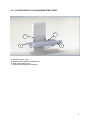
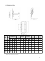
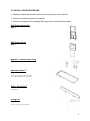
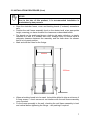
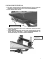
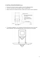
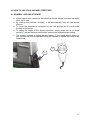
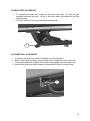
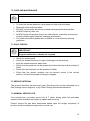
3/12 Easi-Lift Shower Stretcher INSTRUCTIONS FOR USE Codes: 3191-3196 CONTENTS PAGE 1.0 INTRODUCTION 1 2.0 ILLUSTRATION OF YOUR STRETCHER 2 3.0 TECHNICAL DATA 3 4.0 FOR YOUR SAFETY 4 5.0 SURVEYING AND INSTALLATION 5 6.0 HOW TO USE YOUR STRETCHER 11 7.0 CARE & MAINTENANCE 13 8.0 GUARANTEE & SERVICE 16 9.0 CONTINUOUS IMPROVEMENT 17 10. WARRANTY & AFTERSALE 18 1.0 INTRODUCTION Thank you for choosing the Easi-Lift Shower stretcher. The stretcher has been designed to fit into a room where space is at a premium, and provides a durable and economic solution to showering requirements. Height adjustment to suit client, carer and working environment is simply and easily achieved by electrical control across a range of 450mm to 950mm. Its compact and lightweight design is simple to use, and is suitable for use by both children and adults with a maximum user weight of 200kg. When not required for use, the stretcher can simply be stored vertically. IMPORTANT! These instructions should be read by all therapists and carers using the equipment and should be retained for future reference. The product should always be used under adult supervision. Any incorrect use of the product and failure to follow the instructions may put the user at risk or impede the function. If you have any queries using this product or wish for further copies, please do not hesitate to contact Customer Service department on T: +44 (0) 8455 192121 1 2.0 ILLUSTRATION OF YOUR SHOWER STRETCHER A C B D A. Durable non-rip vinyl B. Stainless steel powder coated frame C. Wall mount frame cover D. Safety guard (optional accessory) 2 3.0 TECHNICAL DATA Table Dimensions Code Height Range Wall Frame Guard Rail* Stored Width Max User Weight Shipping Weight Size L mm W mm M mm H mm A mm B mm Height mm Length mm S Mm Kg Kg 3191 1 1400 650 1000 450-950 750 110 145 1400 270 200 82 3192 2 1500 650 1000 450-950 750 110 145 1400 270 200 83 3193 3 1600 650 1000 450-950 750 110 145 1400 270 200 84 3194 4 1700 650 1000 450-950 750 110 145 1400 270 200 85 3195 5 1800 650 1000 450-950 750 110 145 1400 270 200 86 6 1900 650 1000 450-950 750 110 145 1400 270 200 87 3196 * Safety Guard rail optional Accessory 3 4.0 FOR YOUR SAFETY STOP! Please read these instructions CAREFULLY and THOROUGHLY. The patient should NOT be left unattended whilst in the product. Always ensure a responsible therapist or carer is in attendance. The carer should be familiar with the methods of use before transfer of a patient onto the product If fitted, ensure the guard rail is in the ‘up’ position once a patient is on the shower stretcher When storing the product vertically (up position), check to ensure that the locking plunger pin is fully engaged. Regular maintenance checks and cleaning are essential for the safe use of this equipment (see care and maintenance section). Always keep this product away from naked flames, cigarettes and sources of heat including open fireplaces, radiators and heaters. When not in use for periods of time, we recommend isolating the electrical supply. DO NOT fit parts or accessories of other manufacturers to this product unless authorized to do so in writing by Easi-Change Ltd. Failure to follow these instructions will not only invalidate the guarantee but could make the product dangerous to use. Easi-Change Ltd will not accept liability for any injury or damage incurred through such malpractices. In the unlikely event repair work is required it must ONLY be undertaken by EasiChange authorized personnel. If you believe the product or any fitted accessory to be faulty at any time, DO NOT USE – contact Easi-Change by telephone on +44 (0) 8455 192121. This product is CE marked. This certifies that it meets all relevant/applicable European directives. 4 5.0 SURVEYING AND INSTALLATION STOP! If in any doubt, ALWAYS seek ADVICE. Always turn screws clockwise to tighten or anti-clockwise to loosen. 5.1 SURVEYING PROCEDURES Shower stretchers are often installed in small rooms with limited space. In such circumstances it is vitally important to take accurate measurements of the whole room in question, and make a plan to scale if possible. Ensure that the intended wall for installation is strong enough to support the weight of the stretcher plus the patient. If the wall is of brick or concrete construction it will be strong enough to support the equipment without need of the backing board. If the wall is of hollow or soft insulation block construction, then we would always recommend the backing board is used. Check for the position of dado rails, window sills, electrical power points, switches, etc. which may adversely affect the installation. Check there is sufficient room around other facilities, e.g. wash basins, toilets, etc. Remember to take into account the guard rail dimensions (accessory). Check that access to doorways is still possible. Inspect the wall to see if padding/spacing is required to correct wall imperfections. This product requires a 220-240V AC 50Hz or 110V AC 60Hz power source/supply. We recommend connection to a fused spur fitted with 5A fuse. The power connection must be made in an area that is kept free from moisture or connected via a waterproofed socket with an isolation switch. STOP! If in any doubt, ALWAYS seek PROFESSIONAL ADVICE. 5.2 INSTALLATION TOOLS REQUIRED Electric drill, with appropriate drill bits for wood and masonry Tape measure Spirit level Hammer Screw driver set and hex key set Personal Protection Equipment (PPE); gloves, safety glasses. 5 5.3 INSTALLATION PROCEDURE Carefully unpack the shower stretcher and lay all parts on to the floor. Check all component packs are present Check all components for damage that may have occurred during transit Wall Frame Assembly Qty: 1 Wall Frame Cover Qty: 1 Handset, Transformer & Plug Qty: 1 Stretcher Frame1,2 Qty: 1 1.Frame will vary dependent upon length chosen 2.Frame will vary if headrest accessory is chosen Safety Guard Rail3 3.Accessory item Fixing Kit4 Qty: 1 4.Exact contents may vary from illustration 6 5.3 INSTALLATION PROCEDURE (Cont) STOP! Due to the size of this product, it is recommended installation is undertaken by two persons Store the stretcher frame, cover and backing board (if ordered) somewhere safe. Position the wall frame assembly level on the desired wall at an appropriate height, ensuring you have checked for clearances as described before. The bench can be positioned above a bath to aid water collection, or simply fastened to a wall in a suitable wet room. Always check to ensure there is adequate clearance between the assembly and the bath when the shower bed is in its lowest position. Mark and drill the holes for the fixings. 400mm 1250mm Where a backing board is to be used, it should be drilled to take a minimum of 8 fixing screws – check screws do not interfere with the wall frame assembly once mounted. Fix the frame assembly to the wall, checking the wall frame assembly is level and vertical before tightening the fixings – use packing if required. 7 5.3 INSTALLATION PROCEDURE (Cont) Offer up the stretcher frame to the wall bracket assembly, fixing into place using 3 screws per side as shown below (M10 x 20mm screws, total quantity 6) Ensure the screw fixings are tight FIXINGS M10 x 20 Check that the stretcher frame can be rotated from horizontal to vertical without obstruction. Check that the stretcher frame can be stored securely vertically using the plunger locking pin (circled below). To return the stretcher to horizontal, pull the plunger locking pin, and rotate the stretcher downwards. PLUNGER LOCKING PIN 8 5.3 INSTALLATION PROCEDURE (Cont) Connect the electrical system together, as per the diagram below. The 24V control box can be fixed to a wall or suitable shelf. Raise and lower the shower stretcher under load to ensure correct operation. To complete installation, it is necessary to fit the wall frame cover to the wall frame assembly, using the supplied studs (D) and Velcro to fix into place D D . 9 5.4 SHOWER STRETCHER HEAD REST ACCESSORY If the customer has specified on order a head rest accessory, this will be fitted to the shower stretcher at the time of manufacture at the factory. See section 6.0 for instructions on use. 5.5 SAFETY GUARD RAIL ACCESSORY If the customer has specified on order a guard rail accessory, this will be fitted to the shower stretcher at the time of manufacture at the factory. See section 6.0 for instructions on use. 10 6.0 HOW TO USE YOUR SHOWER STRETCHER 6.1 GENERAL USE AND STORAGE Where space is at a premium, the stretcher should always be stored vertically when not in use. By rotating the stretcher vertically, it will automatically lock into the stored position. To return the stretcher to horizontal for use, pull plunger pin (E), and rotate the bed to horizontal. To adjust the height of the shower stretcher, simply press the up or down arrows (F) on the handset until the bed reaches the desired height setting. The system includes a battery backup feature; if the mains power supply is lost, the bed can still be operated using the handset to enable the client to be transferred. F E 11 6.2 HEAD REST ACCESSORY To operate the head rest, simply lift the head rest lever (G) and the gas assisted head rest will rise – let go of the lever when the head rest is at the desired angle To lower, simply lift lever and push the headrest flat. G 6.3 GUARD RAIL ACCESSORY To operate the guard rail rotate it upwards to vertical position. When in the upright position, lift the guard rail to engage the locking pins (H) To lower the guard rail, slightly lift the item to disengage the locking pins (H) Support the guard rail whilst rotating it underneath the bed, to hang freely. H 12 7.0 CARE AND MAINTENANCE IMPORTANT! CLEANING IS RECOMMENDED ON A REGULAR BASIS To clean the shower stretcher use a damp soft cloth with mild soap. Rinse with clean cloth and water. DO NOT use solvents, abrasives, synthetic detergents and wax polishes. ALWAYS wipe dry after use. ALWAYS keep this product away from naked flames, cigarettes and sources of heat including open fireplaces, radiators and heaters. For further information please refer to MHRA or Local Authority cleaning guidelines. 7.1 DAILY CHECKS IMPORTANT! Regular maintenance checks are required Check for missing parts Check the shower stretcher for signs of damage or wear and tear Keep the shower stretcher parts clean Check that the guard rail can be stowed and locked into the vertical position (if fitted) Check that the head rest can be operated (if fitted). Check that the shower stretcher can be securely stored in the vertical position, and that the plunger locking pin engages. 7.2 SERVICE INTERVAL This product should be serviced every year. Servicing must only be undertaken by a Easi-Change service engineer, or by a Easi-Change trained representative. 7.3 NOMINAL SERVICE LIFE Your product has a nominal service life of 7 years, during which full post-sales support will be available with regard to spares and servicing. Product service life has been determined based upon the design complexity of product, and the anticipated exposure to normal use. 13 Good practice dictates all Easi-change products have been designed and manufactured to high levels of safety and quality, and will meet requirements of normal use when maintained in line with our servicing recommendations. STOP! If the product has been out of use for an extended period of time (6 months or more) it should always be serviced prior to being reissued. If the product has been subjected to ‘heavy’ or ‘constant’ use, the service should be reduced to half the recommended period. Constant and/or heavy use is considered to be: Daily use above 7 hours duration Weekly use above 5 days duration Monthly use above 10 months per year Use by a client who is at 90% to 100% of the maximum weight limit of the product. The maximum weight limit must NEVER be exceeded Use by a client who is extremely active, either voluntarily or involuntarily 7.4 EXTENDING NOMINAL SERVICE LIFE We are proud to produce products that have a reputation for quality and durability. We believe our products have the potential to provide benefits to our clients beyond the nominal service life documented above. We will continue to provide full support beyond the nominal service life provided the following conditions are met: 1. A full service schedule has been maintained. 2. A full service and inspection is undertaken at the end of the nominal service life period 3. The product is subsequently serviced annually (or biannually if under ‘heavy/constant’ use conditions) 4. We reserve the right to limit support where parts/components are no longer available 14 7.5 DOCUMENTATION/RECORDS It is the responsibility of the current equipment owner to ensure the ‘Instructions for Use’ manual and any further manuals for accessories fitted to the equipment are handed over to the new owner at the time of exchange/sale It is the responsibility of the current equipment owner to ensure the service and inspection record form is kept up to date 7.6 PRODUCT CONFIGURATION We will document and maintain a record of the original product configuration at the time of first sale We will not be held responsible for any subsequent changes to this configuration unless authorized to do so in writing by Easi-Change Ltd It is the equipment owner’s responsibility to maintain their own records of changes to the equipment configuration and to be able to provide such records to subsequent owners to maintain traceability We recommend an inspection/service by a Easi-Change Service Engineer (or Easi-Change trained engineer) whenever a significant change is made to product configuration to ensure the product is safe to use. If in any doubt, ALWAYS seek ADVICE IMPORTANT REMINDER! DO NOT fit parts or accessories of other manufacturers to this product unless authorized to do so in writing by Easi-Change Ltd. Any servicing or repairs required must be carried out by Easi-Change Ltd (or a Easi-Change trained engineer). If you believe this product to be faulty – DO NOT USE – Contact EasiChange Ltd on T: +44 (0) 1626 835552 If in any doubt, ALWAYS seek ADVICE. 15 8.0 GUARANTEE & SERVICE This product is issued with a full parts and labour guarantee for 2 years from the date of delivery. This guarantee does not apply to accidental damage caused through inappropriate use of the product. This guarantee is issued at the discretion of EasiChange Ltd on RTB (Return to Base) basis. If you have any questions or doubts relating to the safety or use of the product please contact us for advice or assistance on: T: +44 (0) 8455 192121 E: [email protected] 16 9.0 CONTINUOUS IMPROVEMENT Easi-Change Ltd are committed to continuous improvement to their product range. Should you have any suggestions or comments please send them to our product design department at: [email protected] Easi-Change Ltd reserve the right to change the specification or material without prior notice. For catalogues, help and further information on our products please contact us at: Easi-Change Ltd 17 Wentworth Road Heathfield Devon.TQ12 6TL T: +44 (0) 8455 192121 F: +44 (0) 1626 835428 E: [email protected] W: www.easi-change.co.uk 17 10.0 WARRANTY & AFTERSALE 10.1 Product Information Model: Size: Date of Manufacture: Serial Number: Final Inspection: 10.2 Service & inspection record form: Date Procedure Service Personnel Easi-Change Ltd, 17 Wentworth Road, Heathfield, Newton Abbot, Devon.TQ12 6TL T: +44 (0) 8455 192121 F: +44 (0) 1626 835428 E: [email protected] W: www.easi-change.co.uk 18