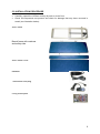
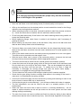
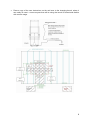
1
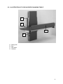
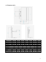
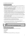
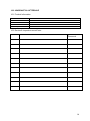
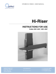
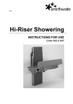
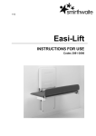
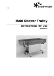
1/12 Hi-Riser INSTRUCTIONS FOR USE Codes 3041-3047, 3051-3057 CONTENTS PAGE 1.0 INTRODUCTION 1 2.0 ILLUSTRATION OF YOUR HI-RISER CHANGING TABLE 2 3.0 TECHICAL DATA 3 4.0 FOR YOUR SAFETY 4 5.0 SURVEYING AND INSTALLATION 5 6.0 HOW TO USE YOUR HI-RISER CHANGING TABLE 9 7.0 CARE & MAINTENANCE 11 8.0 GUARANTEE & SERVICE 12 9.0 CONTINUOUS IMPROVEMENT 13 10.0 14 WARRANTY & AFTERSALE 1.0 INTRODUCTION Thank you for choosing the Easi-Change Hi-Riser changing table. The Hi-Riser Showering is an easy to use two-in-one wall and floor mounted showering and changing table. The robust and yet slim-line design makes it suitable for children and adults of up to 150kg. Its versatility enables it to be an ideal solution for bathrooms as well as swimming pools and hydrotherapy environments. IMPORTANT! These instructions should be read by all therapists and carers using the equipment and should be retained for future reference. The product should always be used under adult supervision. Any incorrect use of the product and failure to follow the instructions may put the user at risk or impede the function. If you have any queries using this product or wish for further copies, please do not hesitate to contact Customer Service department on T: +44 (0) 8455 192121 1 2.0 ILLUSTRATION OF YOUR HI-RISER CHANGING TABLE C B A D A. B. C. D. Safety side Bed Wall frame Handset 2 3.0 TECHNICAL DATA Code Size User Weight (kg) Height Range (mm) Table Dimensions L Length (mm) W Width (mm) M Width (mm) Safety Sides Y Height (mm) Wall Frame A Width (mm) B Depth (mm) C Height (mm) Storage S Width (mm) Shipping Weight (kg) 3041/3051 1 200 400-1000 3042/3052 2 200 400-1000 3043/3053 3 200 400-1000 3044/3054 4 200 400-1000 3045/55 5 200 400-1000 3046/56 6 200 400-1000 3047/3057 7 200 400-1000 1200 550 875 1300 550 875 1400 600 925 1500 600 925 1600 650 975 1700 650 975 1800 650 975 165 165 165 165 165 165 165 700 110 1150 700 110 1150 700 110 1150 700 110 1150 700 110 1150 700 110 1150 700 110 1150 305 80 305 82 305 84 305 86 305 88 305 90 305 92 3 4.0 FOR YOUR SAFETY STOP! Please read these instructions CAREFULLY and THOROUGHLY DO NOT attempt to install and use this product in a wet room. Please follow installation instructions as described in Section 5 carefully and thoroughly. The user should NOT be left unattended whilst on the changing table. Always ensure a responsible therapist or carer is in attendance. The Hi-Riser changing table height should NEVER be adjusted without a carer in attendance. Always ensure the safety side is in the ‘up’ position once a patient is on the table. When storing the product vertically (up position), check to ensure that the locking plunger pin is fully engaged. When not in use for periods of time, isolate the electrical supply. Always keep this product away from naked flames, cigarettes and sources of heat including open fireplaces, radiators and heaters. Regular maintenance checks and cleaning are essential for the safe use of this equipment (see care and maintenance section). DO NOT fit parts or accessories of other manufacturers to this product unless authorised to do so in writing by Easi-Change Ltd. Failure to follow these instructions will not only invalidate the guarantee but could make the product dangerous to use. Easi-Change Ltd will not accept liability for any injury or damage incurred through such malpractices. Any repairs required must be carried out by Easi-Change Ltd authorised personnel. If any part is loose, damaged or functioning incorrectly, DO NOT use until rectified. The Hi-Riser changing table is CE marked. European safety requirements. If you believe the product or any fitted accessory to be faulty at any time, DO NOT USE – contact Easi-Change by telephone on T: +44 (0) 8455 192121 This certifies that it meets all relevant 4 5.0 SURVEYING AND INSTALLATION 5.1 SURVEYING PROCEDURES Changing benches/tables are normally installed in small rooms with limited space. In such circumstances it is vitally important to take accurate measurements of the whole room in question, and make a plan to scale if possible. Ensure that the intended wall for installation is strong enough to support the weight of the changing bench plus the patient. If the wall is of brick or concrete construction, it will be strong enough to support the equipment without the need of the backing board. If the wall is of hollow or soft insulation block construction, then we would always recommend the backing board is used. It is possible to install the bench using wall and floor fixings; care must be taken to survey the junction between wall and floor. If this junction has a large radius fillet, it may be necessary to space the frame off the wall – any such adjustment will impact on the overall installation footprint so must be taken into account when assessing clearances. It is possible using the two leveling bolts to provide stability to the frame at the mating surface with the floor in instances where the customer does not wish to make installation holes in the flooring surface itself. Check for the position of dado rails, window sills, electrical power points, switches, etc which may affect the installation. Check there is sufficient room around other facilities, e.g. wash basins, toilets, etc. Remember to take into account the safety rail dimensions – check that the bench would be capable of adjustment over the height range without fouling. Check that doors would be clear and that access is still possible Inspect the wall to see if padding/spacing is required to correct wall imperfections The Hi-Riser requires a 220-240V AC 50Hz or 110V AC 60Hz power supply. The power connection must be made in an area that is kept free from moisture or connected via a waterproofed socket with isolation switch. STOP! If in any doubt, ALWAYS seek PROFESSIONAL ADVICE 5.2 INSTALLATION TOOLS REQUIRED Electric hand drill, with appropriate drill bits for wood and masonry Set of spanners Tape measure Spirit level Hammer Screw driver Personal Protection Equipment (PPE); gloves, safety glasses 5 5.3 INSTALLATION PROCEDURE Carefully unpack the Hi-Riser and lay all parts on to the floor Check all components are present and check for damage that may have occurred in transit (see illustration below): Wall Frame Bench frame with mattress and safety side Wall Frame Cover Handset Transformer and plug Fixing screw pack 6 STOP! It is strongly recommended that two people carry out the installation due to the weight of the product Store the wall frame cover and backing board (if ordered) safely until required Offer up the wall frame into the desired position to mark and drill the holes for the fixings; adjust the two leveling bolts as required. Where a backing board is to be used, it should be drilled to take fixing screws (minimum 8) – check the screws do not interfere with the wall frame when mounted. Fit the fixing bolts and loosely fit the frame to the wall or backing board, being careful not to trap the electrical cable Before tightening fixings, check frame is vertical in all directions, and if necessary fit packing to achieve Before offering up the bench frame to the wall frame, firstly remove the ball end screw that has been loosely fitted to the left-hand hinge The bench frame can now be fixed to the wall frame; the two hinge bolts that are loosely fitted to the wall frame should be removed, and a small amount of Loctite applied to the first 5mm. Offer up the bench and insert the two bolts previously prepared but do not over-tighten. The bolts must not protrude more than approx 1mm. With the bench frame now in place in the horizontal position, reconnect the ball end screw previously removed and tighten with the appropriate spanner. The bench should now be raised into the vertical position and locked in position. Locate the lower end of the gas spring (which is fitted to the back of the wall frame) and fit to the ball end on the hinge of the bench frame. This can be snapped into place by pressing the cup firmly onto the ball end. To enable this to be done, it might be necessary to disengage the locking plunger and push the bench frame slightly – remember to re-engage the locking plunger when finished The two side trims may now be fitted using the plastic push fit retainers supplied. Check that the gas spring functions correctly and assists in the raising of the bench – make sure it is checked with the safety rail fitted. Connect the electrical supply and test the bench by raising and lowering to each of the limits of travel to ensure there are no obstructions. Confirm the plunger pin works effectively – you will hear a distinct click when it engages The 24V transformer can now be fixed to the wall in a suitable position, or on a bracket/shelf. Raise and lower the bench with a load to ensure it is working satisfactorily – do not repeat in rapid succession as this will put stress on the motor system and can cause damage through overheating. The main front cover can now be refitted and fixed into place by sliding it down behind the bench so that the Velcro holds the top firmly. Use the studs supplied to fix into place. 7 Place a copy of the user instructions on the wall near to the changing bench, where it can easily be read – ensure anyone that will be using the bench is trained and familiar with correct usage. 8 6.0 HOW TO USE YOUR HI-RISER CHANGING TABLE IMPORTANT! For non-hoist transfers always ensure the safety side is in the fully stowed position (down). When the user has been transferred onto the Hi-Riser table, please ensure safety side is in the fully upright position. Ensure that the electrical supply to the changing table is ON The bed can be lowered from its stowed position by using one hand to gently press the mattress against the frame, and at the same time using your second hand to release the plunger locking pin which is situated by the right hand hinge (shown circled opposite). When unlocked, use both hands to lower the bed into the horizontal position. Before transferring a patient, adjust the height of the bed by using the hand controller ‘Up’ and ‘Down’ buttons/arrows, as shown opposite. With the patient safely transferred onto the bed, rotate the safety rail into the vertical position and allow it to drop into its retaining slot – check it is in place by gently pulling outwards (towards your body). The bench can now be raised to the optimum position, which will depend on the carer To dismount the patient, the process is the reverse of the steps described above 9 Once the patient has been dismounted, ensure the bed mattress is wiped as per the cleaning instructions in Section Y. The bench can be stowed away by lifting it up with both hands, and when vertical press firmly to slightly compress the mattress – listen for a ‘click’ which indicates that the plunger locking pin has engaged into the locked position. Confirm this by gently pulling the bed toward you. N.B. If using a hoist system for patient transfer, the patient can be lowered onto the bed when already set at the desired height, with the safety rail set to the vertical position. 10 7.0 CARE AND MAINTENANCE IMPORTANT! Cleaning is recommended on a regular basis To clean the mattress use a damp soft cloth with mild soap Rinse with clean cloth and water DO NOT use solvents, abrasives, synthetic detergents and wax polishes ALWAYS wipe dry after use ALWAYS keep this product away from naked flames, cigarettes and sources of heat including open fireplaces, radiators and heaters For further information please refer to MHRA or Local Authority cleaning guidelines 7.1 MAINTENANCE CHECKS IMPORTANT! Regular maintenance checks are required 7.1.1 DAILY CHECKS Check the mattress for signs of damage or wear and tear Keep the upholstery and metal parts clean Check the safety rail can be stowed and locked into the vertical position Check that the bed rises and lowers when activated by the handset Check that the bed can be securely stored in the vertical position, and that the plunger locking pin engages. 7.2 SERVICE INTERVAL The Hi-Riser changing table should be serviced every 1 year. Servicing must only be undertaken by a Easi-Change service engineer, or by a Easi-Change trained representative. 11 8.0 GUARANTEE & SERVICE The product is issued with a full parts and labour guarantee for 2 years from the date of delivery. This guarantee does not apply to accidental damage caused through inappropriate use of the product. This guarantee is issued at the discretion of EasiChange Ltd on RTB (Return to Base) basis. If you have any questions or doubts relating to the safety or use of the product please contact us for advice or assistance on: T: +44 (0) 8455 192121 E: [email protected] 12 9.0 CONTINUOUS IMPROVEMENT Easi-Change Ltd are committed to continuous improvement to their product range. Should you have any suggestions or comments please send them to our product design department at: [email protected] Easi-Change Ltd reserve the right to change the specification or material without prior notice. For catalogues, help and further information on our products please contact us at: Easi-Change Ltd 17 Wentworth Road Heathfield, Devon.TQ12 6TL T: +44 (0) 8455 192121 F: +44 (0)1626 835428 E: [email protected] W: www.easi-change.co.uk 13 10.0 WARRANTY & AFTERSALE 10.1 Product Information Model: Size: Date of Manufacture: Serial Number: Final Inspection 10.2 Service & inspection record form: Date Procedure Service Personnel 14 Easi-Change Ltd, 17 Wentworth Road, Heathfield, Newton Abbot, Devon.TQ12 6TL T: +44 (0) 8455 192121 F: +44 (0) 1626 835428 E: [email protected] W: www.easi-change.co.uk 15