1
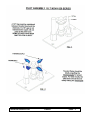
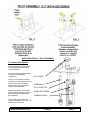
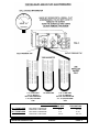
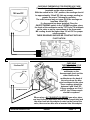
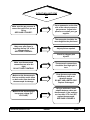
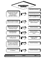
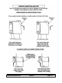
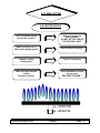
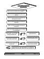
FOR INSTALLERS AND SERVICE TECHNICIANS ONLY
GAS
FIREPLACE
SERVICE
MANUAL
Sherwood Industries Ltd. Duplication of this document is prohibited. All rights reserved.
August 2003
C-10100
This is a service guide designed by SHERWOOD INDUSTRIES LTD.
We hope this manual will assist you to identify and correct operational concerns you might
experience in all ENVIROGAS appliances.
This service guide is designed for TRAINED SERVICE TECHNICIANS AND INSTALLERS.
This guide is NOT to be used by the homeowner.
If after reading this guide and following our recommendations and the problem still excists,
please do-not hesitate to call our technical department.
Technical Division
SHERWOOD INDUSTRIES LTD.
TABLE OF CONTENTS
PAGE
1) PILOT WILL NOT STAY LIGHT
A) IGNITION SYSTEM………………………………………………………. 1
B) IGNITION SYSTEM OK BUT PILOT WILL NOT LIGHT……………... 3
2) PILOT WILL NOT STAY LIT……………………………………………………… 7
3) MAIN BURNERS WILL NOT LIGHT…………………………………………….. 9
4) MAIN BURNERS WILL NOT STAY LIT…………………………………………. 11
5) SOOTING (ALL MODELS)…………………………………………………….…. 15
6) FLAME LIFTING
A) B-VENTED………………………………………………………………... 17
B) DIRECT VENTED………………………………………………………... 18
7) BLOWER OPERATION ………………………………………………………….. 19
8) ORIFICE SIZING CHART………………………………………………………… 20
9) STEP BY STEP SERVICE INSTRUCTIONS…………………………………… 21
10) GLOSSARY………………………………………………………………………. 23
SUGGESTED TOOLS LIST FOR SERVICING
GAS LEAK DETECTOR
MANOMETER
MULTIMETER
CORDLESS DRILL
WIRE STRIPPER/CRIMPER
WRENCHES, STANDARD AND METRIC
SCREWDRIVERS
(TORX T20)
METAL SNIPS
JUMPER WIRES
NUMBERED DRILLS ((DMS))
Sherwood Industries Ltd.
ENVIRO
2003
1(PILOT WILL NOT LIGHT
NO SPARK
A) IGNITION SYSTEM
Make sure that wires are not
broken, frayed and that all
connections are tight at both
the piezo ignitor and
electrode.
Replace with only
manufactures parts
Make sure that ceramic on the
electrode is not broken.
Carefully try to spin the
porcelain.
IF IT DOES, replace
electrode.
Make sure a 1/8” (3.175mm)
gap is maintained between
electrode and pilot hood.
SEE PAGE 2 FIGURE 1.
Replace electrode.
Retighten hex nut on back
of the ignitor and make
sure bracket is secure on
the valve.
Make sure the piezo ignitor is
not loose.
Make sure piezo ignitor is
working properly. Place a
screwdriver next to ignitor,
and press ignitor. If it sparks,
OK.
Sherwood Industries Ltd.
IF IT FAILS, replace piezo
ignitor.
ENVIRO
PAGE 1
3.175mm
Sherwood Industries Ltd.
ENVIRO
PAGE 2
B) PIEZO IGNITOR OK BUT PILOT WILL STILL NOT LIGHT
Make sure all gas lines have
been connected with no
leaks.
Correct if necessary, test
for gas leaks in an
approved manner.
Make sure that the gas is
“ON” (NG) Natural gas and
(LP) Propane tanks are full.
Correct if necessary.
Make sure the appliance
service valve is in the “ON”
position.
SEE PAGE 4 FIGURE 3.
Turn service valve to the
“ON” position.
Test to make sure there is no
air in the gas line.
SEE PAGE 4 FIGURE 3.
Use a match to see if air or
gas comes from the pilot
assembly.
Make sure that the valve has
not reset itself.
(All valves have an interlock
safety device.)
Wait 60 seconds for the
safety to reset itself.
Make sure pilot injector is
not clogged.
Sherwood Industries Ltd.
Clean the pilot injector if
necessary.
ENVIRO
PAGE 3
EXPLODED VIEW S.I.T PILOT ASSEMBLY
To remove pilot injector:
Remove the two screws that hold
the pilot assembly to the burner
control assembly.
Lift the assembly straight up being
careful not to damage any
components.
Using a 10 mm wrench undo the
securing nut on pilot tubing and pull
tubing down to access injector.
Being careful not to damage the
ceramic spark electrode.
Replace the injector and reinstall
the pilot tubing, always to perform a
gas leak test before lighting the
pilot assembly.
PILOT HEAD
THERMOPILE
PILOT INJECTOR
SPARK ELECTRODE
THERMOCOUPLE
The number on the side of the
injector will determine the size. This
number is in millimeters.
Sherwood Industries Ltd.
ENVIRO
PAGE 4
3.5” wc BELOW 0
3.5” wc ABOVE 0
INLET GAS PRESSURE
7” wc (NG) NATURAL
GAS
NO PRESSURE
1.75” wc BELOW 0
1.75” wc ABOVE 0
OUTLET GAS PRESSURE
3.5 “ wc (NG) NATURAL
GAS
SUPPLY PRESSURES
NATURAL GAS
50% TURN DOWN
33% TURN DOWN
MAX SUPPLY PRESSURE
MIN SUPPLY PRESSURE
MAX SUPPLY PRESSURE
MIN SUPPLY PRESSURE
Sherwood Industries Ltd.
7” wc
5” wc
7” wc
4.5” wc
ENVIRO
PROPANE GAS
12” wc
11.5” wc
13” wc
10.5” wc
PAGE 5
190 mv DC
CHECKING THERMOPILE FOR PROPER VOLTAGE
Place the leads of the multimeter on the TP/TH and TP
terminals on the valve as shown.
With the switch in the “ON” position, the readings should
be approximately 190mV DC (this an average reading) or
greater for proper Thermopile operation.
The main burners may not come ON if the readings are
less than 145mV DC.
If a thermostat has been installed. Place the
ON/OFF/THERMO switch in the THERMO position; place
the leads of the multimeter on the TP/TH and TH terminals
on the valve or on the connections at the thermostat.
MV reading should be higher than 190 mV DC for proper
valve operation.
THESE READINGS SHOULD BE CONSTANT WITH NO
FLUCTUATION.
CHECKING
THERMOCOUPLE FOR
PROPER VOLTAGE
Place one lead from the
multimeter on the
thermocouple lead, and the
other lead from the
multimeter on the back of
the valve where the blue
wire is soldered to the valve.
These readings should be
between 8 and 16mV DC.
If these readings are 2 to 6
mV DC, the Thermocouple
should be replaced
2 to 6mv DC
THERMOCOUPLE
When using a S.I.T EUROSIT 630 SERIES gas valve, place
one lead from the multimeter on the thermocouple lead and
the other lead into the adapter located on the back of the
valve, there are two blue wire a inserted into this adapter.
Sherwood Industries Ltd.
ENVIRO
PAGE 6
2) PILOT WILL NOT STAY
LIT
Use a manometer on the inlet
side of the valve to measure
gas pressure. Adjust inlet
pressure or contact your gas
supplier.
Make sure the gas pressure is
correct for type of fuel you are
using.
SEE PAGE 5 FIGURE 7.
Thermocouple should be the
same height as the pilot hood.
Make sure pilot flame is
engulfing the top 3/8” of the
thermocouple.
SEE PAGE 2 FIGURE 2.
Adjust pilot as required.
Check for clogged pilot
injector.
Make sure thermocouple
connections on valve are
tight.
DO NOT OVER TIGHTEN!!!
Thermocouple connections
should be hand tight plu1/4
turn.
Make sure the thermocouple
line has no kinks and is clean
on both ends. Also check the
thermocouple for damage.
Clean thermocouple ends
with Emery cloth or an
abrasive sponge.
DO NOT USE A METAL FILE.
Replace if damaged.
Make sure the thermocouple
has proper voltage (DC
VOLTAGE).
Using a multimeter, insert
adapter between valve and
thermocouple, if the readings
are less than 2 TO 6 mV DC,
replace thermocouple.
SEE PAGE 6 FIGURE 8.
Sherwood Industries Ltd.
ENVIRO
PAGE 7
S.I.T EUROSIT MODULATING 630 SERIES
Sherwood Industries Ltd.
ENVIRO
PAGE 8
3) MAIN BURNERS WILL
NOT LIGHT
Make sure gas valve knob is
in the “ON” position.
SEE PAGE 8 FIGURE 6.
Correct if necessary.
Turn valve to the “ON”
position.
Make sure that the “ON-OFF
THERMO” switch is in the
“ON” position.
Turn switch “ON”.
Make sure that the
thermostat is “NOT” in the
lowest position.
Turn thermostat “UP”.
Replace damaged wires as
necessary. Gently squeeze
connectors with a pair of
pliers and reinstall wires.
Make sure that all control
wires are not damaged,
broken or frayed and that all
wire connections are tight.
Make sure that the
thermopile connections are
tight on the valve.
Tighten the two screws on
valve if necessary
“TP/TP-TH” terminals on
valve.
Make sure millivolt readings
from thermopile are within
manufactures
specifications. MAKE SURE
MILLIVOLT READINGS ARE
CONSTANT.
SEE PAGE 6 FIGURE 8.
Place leads of multimeter
on the “TP/TH-TP”
terminals on gas valve. If
the readings are less than
145mV DC, replace
thermopile
Continued on next page.
Sherwood Industries Ltd.
ENVIRO
PAGE 9
MAIN BURNERS WILL NOT LIGHT CON’T.
Bypass spill switch with a
jumper wire as shown. If the
unit starts, replace the spill
switch. DO NOT LEAVE BY
PASSED IN.
Check spill switch operation
on B-vented models only
SEE PAGE 10 FIGURE 9.
Check the “ON-OFF” switch
and thermostat for proper
operation.
Use a jumper wire. If the unit
starts, replace switch if
necessary.
Make sure that the main
burner orifices are not
clogged or damaged.
Remove the top tray.
Remove orifice and clean.
Replace if damaged.
Sherwood Industries Ltd.
ENVIRO
PAGE 10
4) MAIN BURNERS WILL
NOT STAY LIT
Adjust pilot if necessary.
Make sure pilot flame engulfs
the thermopile and does
“NOT” have a yellow
luminous flame.
SEE PAGE 4 FIGURE 4.
Check outlet gas pressure.
Check for clogged pilot
injector or blocked air inlet.
Using a multimeter check
thermopile. If not constant
replace thermopile.
Make sure millivolt readings
from thermopile are constant.
Make sure all wiring is not
damaged or broken and all
connections are tight.
Correct if necessary.
By pas spill switch.
If unit starts, replace spill
switch.
B-VENTED MODELS
Check spill switch.
Check to make sure the vent is
drafting properly.
Check for spillage.
SEE PAGE 12.
Make sure all venting meets
manufactures specifications
as well as local gas and
building code requirements.
Correct if necessary.
Check chimney for blockage
or restriction.
Sherwood Industries Ltd.
Correct if necessary.
ENVIRO
PAGE 11
Sherwood Industries Ltd.
ENVIRO
PAGE 12
SAMPLE DIRECT VENT CHIMNEY INSTALLATIONS
ALL MODELS
Sherwood Industries Ltd.
ENVIRO
PAGE 13
SAMPLE B-VENTED CHIMNEY INSTALLATIONS
ALL MODELS
INSERT MODELS
MUST BE FULLY
LINED AND SEALED
Sherwood Industries Ltd.
ENVIRO
PAGE 14
5) SOOTING
Make sure log placement is
in the correct location.
Correct to manufactures
specifications.
Correct if necessary.
Outside air supply may be
required on B-vented
models.
Make sure there is sufficient
air supply.
Check air shutter on the
venturi tube for proper
primary air adjustment.
SEE PAGE 16.
Increase primary air.
Open air shutter.
Make sure orifice matches
that on the rating plate.
Correct if necessary.
Make sure outlet (manifold)
pressure is correct.
Use a manometer to check
the gas pressure.
SEE PAGE 5 FIGURE 7.
Make sure the unit has been
derated for high altitude
applications.
(if required)
Correct if necessary.
Check to make sure that the
vent is drafting properly.
Sherwood Industries Ltd.
Correct if necessary.
ENVIRO
PAGE 15
IF THE AIR SHUTTER IS
OPENED WIDER, THE
FLAME COULD APPEAR
ALMOST ALL BLUE
WITH FLAME LIFTING
BEING THE END RESULT
IF OPENED TOO MUCH
WITH THE AIR SHUTTER
SET PROPERLY, THE
FLAME WILL SIT ON THE
BURNER PORT AND THE
FLAME PATTERN WILL
START AT THE BOTTOM
WITH A BLUE FLAME
THEN TURNING TO A
WHITE ALMOST
YELLOW FLAME WITH A
SLIGHT ORANGE EDGE
AS THE AIR SHUTTER
IS CLOSED, THE
FLAME COULD
APPEAR TALLER WITH
A VERY LAZY BLACK
ORANGE TIPPED
FLAME PRODUCING
CARBON (SOOT)
Sherwood Industries Ltd.
ENVIRO
PAGE 16
6) FLAME LIFTING
A) B-VENTED MODELS
Adjust air shutter, by
closing shutter.
DO NOT GO TOO FAR OR
THE UNIT WILL SOOT.
Check air shutter on the
burner tube (venturi).
Make sure there are no
leaks in the venting system.
Seal venting if necessary.
Improper venting
configuration.
Correct if necessary.
Make sure that manifold
(outlet).
Pressure is correct.
Use a manometer to check
gas pressure.
SEE PAGE 5 FIGURE 7.
Sherwood Industries Ltd.
ENVIRO
PAGE 17
B) DIRECT VENT MODELS
Check air shutter on the
burner tube (venturi).
Adjust air shutter.
Close until flame sits onto
the burner ports.
Seal exhaust tube with high
temperature silicone.
Also make sure that
combustion air pipe is
sealed.
Make sure there are no leaks
in the venting system.
Make sure the unit is not
recirculating flue products.
Check flue for blockage or
high wind situations.
Make sure the gas pressure
is correct for fuel being used.
Use a manometer to check
gas outlet (manifold)
pressure.
SEE PAGE 5 FIGURE 7.
Make sure the orifice size is
the same as the rating plate.
Correct if necessary.
Add a vent restrictor ring.
SEE OWNERS MANUAL.
Sherwood Industries Ltd.
Only if necessary.
ENVIRO
PAGE 18
7) BLOWER DIAGNOSIS
ALL MODELS
Check to make sure that the fan is plugged in.
Make sure the fan control knob is in the “ON”
position.
Make sure the two wires are connected to the
fan temperature sensor.
Make sure that the two wires are connected to
the blower.
Make sure there are no broken, damaged or
frayed wires.
Make sure that the fan sensor is secure and that
it is not damaged.
If the blower does not work,
replace the blower.
Using a supply cord connected
to the blower, plug the blower
directly into wall outlet.
If the blower works, replace
the fan temperature sensor
By pass the fan temperature
sensor with a jumper wire.
By pass the fan controller with
a jumper wire.
If the blower does not work,
replace the fan controller.
MAKE SURE THAT THE FAN SENSOR IS AT OPERATING
TEMPERATURE BEFORE TESTING THE FAN CONTROLLER.
Sherwood Industries Ltd.
ENVIRO
PAGE 19
ORIFICE SIZING
CHART
DRILL#
70
69
68
1/32
67
66
65
64
63
62
61
60
59
58
57
56
3/64
55
54
53
1/16
52
51
50
49
48
5/64
47
46
45
44
43
42
3/32
41
40
39
38
37
36
7/64
35
34
SIZE
.0280
.0292
.0310
.0313
.0320
.0330
.0350
.0360
.0370
.0380
.0390
.0400
.0410
.0420
.0430
.0465
.0469
.0520
.0550
.0595
.0625
.0635
.0670
.0700
.0730
.0760
.0781
.0785
.0810
.0820
.0860
.0890
.0935
.0938
.0960
.0980
.0995
.1015
.1040
.1065
.1094
.1100
.1110
SHERWOOD IDUSTRIES LTD.
NATURAL GAS
3.5”
3.8”
1991
2074
2165
2256
2440
2542
2487
2591
2600
2709
2765
2881
3110
3240
3291
3429
3476
3622
3666
3820
3862
4024
4062
4232
4268
4447
4479
4667
4695
4892
5490
5720
5585
5819
6865
7153
7680
8002
8989
9366
9918
10334
10238
10667
11398
11876
12441
12962
13530
14097
14665
15279
15487
16136
15646
16302
16658
17356
17072
17787
18778
19565
20111
20954
22197
23127
22339
23275
23399
24379
24384
25406
25137
26190
26157
27253
27462
28613
28798
30005
30388
31661
30722
32009
31283
32594
ENVIRO
PROPANE GAS
10”
11”
5221
5476
5678
5956
6400
6713
6524
6843
6820
7153
7253
7607
8158
8557
8631
9053
9117
9563
9617
10087
10130
10625
10655
11176
11195
11742
11748
12322
12314
12916
14400
15104
14649
15365
18008
18888
20146
21131
23578
24730
26014
27286
26854
28167
29896
31357
32633
34228
35490
37225
38467
40347
40622
42608
41039
43045
43695
45831
44780
46969
49256
51663
52753
55331
58221
61067
58596
61460
61377
64377
63961
67087
65933
69156
68610
71964
72032
75553
75537
79229
79707
83603
80582
84522
82055
86066
PAGE 20
STEP BY STEP SERVICE INSTRUCTIONS
These appliances do require to be serviced. Our best recommendation is that the appliance be
serviced (1) once a year, maybe just before the heating season starts.
Annual service should and inspection should include:
⇒
⇒
⇒
⇒
⇒
⇒
⇒
⇒
⇒
⇒
⇒
⇒
Open the two side panels or remove the face frame from the appliance. Vacuum all areas
around the convection blower making sure there are no obstructions near the convection
blower or in the impeller fan blades.
EG-95 inserts and freestanding fireplaces convection blowers do require lubrication. Use
lightweight oil 20 SAE, 3 in 1 oil, or sewing machine oil (2 drops only). Too much oil will
contract dust and dirt, which could cause premature breakdown of the convection blower.
Check all wiring for loose connections and damage to any of the wires.
Check to make sure that the flue is connected and that the flue is not plugged and that it is
free from obstructions.
Also check to make sure that the fresh air, if installed, is not clogged and that it is free from
obstructions.
Open the glass door by undoing the ½” bolt on the right hand side of the appliance, swing the
door all the way open and gently lift the door of the two pins on the left hand side of the
appliance.
Carefully remove the log set from the firebox. NOTE: The edges of the logs become brittle
with heat over time so they could be damaged when removing the logs. Remove the glowing
ember material making sure not to drop any of the ember material, which could drop into air
passages or drop on the pilot assembly.
Inspect the pilot assembly for build up on the Thermocouple and Thermopile; also make sure
that the pilot assembly has not been damaged.
Vacuum all areas inside the firebox in and around the burner tray, control panel and
surrounding areas.
Carefully replace the logs and glowing embers into the firebox making sure that the log and
ember material are in the correct location (refer to the owner and operators manual).
Inspect the door gaskets to make sure that it is not cracked broken or frayed. Place the door
assembly back on the two pins on the left side of the appliance, close the door and tighten the
½” bolt on the right hand side, make sure that the gasket is fully sealed (pay special
attention to the corners of the bay window). Visually check for a small gap, if there is a
gap, open the door and fluff the gasket up a little, reinstall the glass and re inspect the gasket
to make sure it has sealed.
Relight the appliance, before you turn the gas control knob to the “ON” position, do a millivolt
reading from the thermopile. Turn the gas control knob to the “ON” position, before the main
burners are turned “ON” do another millivolt reading at the thermopile to make sure there is no
change.
Sherwood Industries Ltd.
ENVIRO
PAGE 21
⇒
⇒
⇒
⇒
Turn the switch to the “ON” position; check the millivolt readings at the thermopile make sure
that the readings meet manufacters specifications. Turn the unit “OFF”.
Install a manometer on the inlet side of the gas valve marked (E), re light the appliance make
sure that the inlet pressure meets the manufactures specifications.
Shut the unit “OFF” once again and do an outlet (manifold) pressure test. Relight the
appliance and make sure the outlet (manifold) pressure is within manufactures specifications.
FINALLY, check to make sure that the unit is venting properly by placing a match in the
dilution air outlet or in the draft tube on insert models. If the match is blown out then there is
some sort of restriction. Correct if necessary.
CLEANING THE APPLIANCE
⇒
Only use a very soft cloth an a non abrasive cleaner, DO NOT use any alcohol’s, mineral
spirits, gasoline’s or abrasive cleaners.
When cleaning the glass there could be some stubborn material left on the glass, DO NOT
use a scraper or abrasive cleaning agents on the glass because this could scratch the glass
which in turn will make he glass weak at the point of the scratch. There is a glass cleaner that
is specially designed for gas fireplaces, which can be purchased at your local dealer.
Sherwood Industries Ltd.
ENVIRO
PAGE 22
10) GLOSSARY
B-VENTED SYSTEM
A venting system using only approved double wall pipe and approved B-vent components. This
system also uses room air for proper venting action through the dilution air inlet mounted on the
back of the unit.
CONTINUITY TEST
By using a multimeter set on OHMS, is determined if the circuit is complete, or continuous (no
break in the circuit).
DIRECT VENT SYSTEM
A venting system sealed from the structure for both the exhaust gases and fresh air supply.
ELECTRODE (ignition)
Receives spark from the piezo ignitor to light the pilot.
IGNITOR (piezo)
A component used to create an electrical spark to the electrode to light the pilot.
IMPINGEMENT
When flame comes in contact with physical components. Impingement can cause incomplete
combustion resulting in carbon monoxide production as well as soot.
MANOMETER
Instrument used to measure gas pressure.
MILLIVOLT
One –one thousands (1/1000) of a volt (.001mV DC)
MULTIMETER
Instrument used to measure Volts. Amps, Ohms, (Volts DC, AC)
ORIFICE
A component that controls gas flow through the burners.
PILOT INJECTOR
A component that directs gas flow through the pilot assembly.
PRESSURE REGULATOR
A device used to maintain downstream gas pressure.
RATING PLATE
A plate in the appliance which shows all certifications and what type of fuel and what the
appliance is rated for (example: BTU’s, gas type, serial#, etc.).
SOOTING
Carbon build up produced by incomplete combustion of the fuel being used.
SPILLAGE
When flue products do not properly exit the structure through the venting system.
SPILL SWITCH
A temperature sensitive switch designed to shut the appliance off in the case of improper
venting action.
THERMOCOUPLE
A device used to generate power with heat from the pilot, up to 25mV DC.
THERMOPILE
A device used to generate power with heat from the pilot, up to 750mV DC.
VENTURI
Where gas and air are mixed before entering the burner tube.
Sherwood Industries Ltd.
ENVIRO
PAGE 23