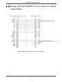
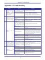
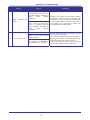
1
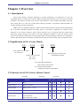
Googol Technology (Shenzhen) Co., Ltd. Add.: W211, 2/F, West Building, SZHK Industry, Education and Research Base, South Area, High-tech Industry Park, Shenzhen, PRC Tel. : (+86 755) 26970823 26970824 26970835 26970817 Fax. : (+86 755) 26970821 Email: [email protected] Web: http://www.googoltech.com.cn/ Googol Technology (HK) Co., Ltd. Add.: Room 3639, Annex Building, The Hong Kong University of Science and Technology, Clear Water Bay, Kowloon, Hong Kong Tel. : (+852) 2358-1033 Fax. : (+852) 2719-8399 GE-S Series Motion Controller User Manual Be sure to hand over this manual to the user. Thank you for the purchase of GE-S Series Motion Controller. Please read this manual carefully to guarantee the correct operation before the controller is used. Please keep this manual carefully for reading and referring at any time. Copyright Statement Copyright Statement Googol Technology (Shenzhen) Co., Ltd. All rights reserved. Googol Technology (Shenzhen) Co., Ltd. (Googol Technology hereafter) reserves the right to modify the products and the product specifications described in this manual without advance notice. Googol Technology is not responsible for any direct, indirect, special, incidental or consequential damage or liability caused by the improper use of this manual or this product. This product is not designed and manufactured for using in the machinery and systems involved in human life. If you plan to use this product for this type of machinery and systems, please contact with Googol Technology. If this product is used in the equipment which may endanger the personal life or cause the significant loss, the appropriate safety devices should be installed. Googol Technology owns the patent, copyright and related intellectual property of this product and its software. No duplication, reproduction, processing, using of this product and its related parts directly or indirectly is granted without the authorization by Googol Technology. It is dangerous of the machinery in moving. It is the responsibility of the user to design the effective error handling system and security protection as the part of the machinery. Googol Technology has no obligation or responsibility for any incidental or consequential damages. Foreword Foreword Thank you for using Googol Motion Controller Your own control system will be established supported by our first-class motion controller, perfect after-sale service and high-efficiency technical support. More information about Googol products The web of Googol Technology is http://www.googoltech.com.cn. More information about Googol Technology and its products can be obtained on the web, including the introduction of Googol Technology, products, technical support, latest products and so on. You can also call (+86 0755-26970839/26970817) to consult more information about Googol Technology and its products. Technical Support and After-sale Service You may get our technical support and after-sale service through the following approaches: Email: [email protected] Tel.: (+86 755) 26970823, 26970824, 26970835, 26970817 Add.: Googol Technology (Shenzhen) Co. Ltd. W211, 2/F, West Building, SZHK Industry, Education and Research Base, High-tech Industry Park, Shenzhen, PRC Post: 518057 Purpose of this Programming Manual By reading this manual, you can understand the basic structure of GE-S Motion Controller, learn the installation of motion controller, and study the connection of motion controller, motor control system and laser control system. Finally, you can complete the debug of motion control and laser control system. User of this Programming Manual This manual is applicable for those engineering staff with the basic knowledge of hardware and certain understanding of control. Contents of this Programming Manual There are three chapters and appendix in this manual. The first chapter is overview which introducing GE-S Series Motion Controller and how to buildup the electromechanical control system. The second chapter is quick start which introducing the installation and wiring of motion controller, the installation of drive program. The third chapter is system debug. And the technology specification of motion controller, typical wiring and troubleshooting are provided in appendix. Relevant Documents Please refer to “GE-S Series Motion Controller – Programming Manual” provided together with the product about the programming of GE-S Series Motion Controller. Contents Contents CHAPTER 1 OVERVIEW ............................................................................................................... 1 1.1 INTRODUCTION ........................................................................................................................... 1 1.2 SIGNIFICATION OF GE-S SERIES MODELS.................................................................................... 1 1.3 FUNCTION LIST OF GE-S SERIES MOTION CONTROL................................................................... 1 1.4 COMPONENTS OF GE-S CONTROL SYSTEM ................................................................................. 2 CHAPTER 2 QUICK START .......................................................................................................... 4 2.1 OPEN FOR CHECKUP .................................................................................................................... 4 2.2 OVERALL STRUCTURE OF GE-S SERIES MOTION CONTROLLER .................................................. 4 2.3 INSTALLATION PROCEDURES ....................................................................................................... 7 2.3.1 Step 1: Insert the Control System into the Computer .......................................................... 7 2.3.2 Step 2: Install the Drivers of Motion Controller (only for Windows OS) ............................ 7 2.3.3 Step 3: Establish the Communication between the Host and the Motion Controller .......... 7 2.3.4 Step 4: Connect the Motor with the Driver ......................................................................... 8 2.3.5 Step 5: Connect the Motion Controller with the Terminal Board........................................ 8 2.3.6 Step 6: Connect the Driver, System I/O with the Terminal Board ....................................... 8 CHAPTER 3 SYSTEM DEBUG .................................................................................................... 16 APPENDIX A TECHNICAL SPECIFICATION.......................................................................... 17 APPENDIX B TYPICAL WIRING ............................................................................................... 19 B.1 WIRING WITH PANASONIC MSDA SERIES DRIVER IN VELOCITY CONTROL MODE ................... 19 B.2 WIRING WITH PANASONIC MSDA SERIES DRIVER IN POSITION CONTROL MODE..................... 20 B.3 WIRING WITH SANYO DENKI PV1 SERIES DRIVER IN VELOCITY CONTROL MODE ............... 21 B.4 WIRING WITH SANYO DENKI PV1 SERIES DRIVER IN POSITION CONTROL MODE ................ 22 B.5 WIRING WITH SANYO DENKI PY0/PY2 SERIES DRIVER IN VELOCITY CONTROL MODE ...... 23 B.6 WIRING WITH SANYO DENKI PY0/PY2 SERIES DRIVER IN POSITION CONTROL MODE ........ 24 B.7 WIRING WITH SANYO DENKI PU SERIES DRIVER IN VELOCITY CONTROL MODE ................. 25 B.8 WIRING WITH YASKAWA SERVOPACK SERIES DRIVER IN VELOCITY/MOMENT CONTROL MODE ..................................................................................................................................... 26 B.9 WIRING WITH YASKAWA SERVOPACK SERIES DRIVER IN POSITION CONTROL MODE ........ 27 B.10 WIRING WITH YASKAWA SGDE SERIES DRIVER IN POSITION CONTROL MODE ................... 28 B.11 WIRING WITH YASKAWA SGDM DRIVER IN VELOCITY CONTROL MODE ............................ 29 B.12 WIRING WITH YASKAWA SGDM DRIVER IN POSITION CONTROL MODE.............................. 30 B.13 WIRING WITH MITSUBISHI MELSERVO-J2-SUPER SERIES DRIVER IN VELOCITY CONTROL MODE ..................................................................................................................................... 31 B.14 WIRING WITH MITSUBISHI MELSERVO-J2-SUPER SERIES DRIVER IN POSITION CONTROL MODE ..................................................................................................................................... 32 B.15 WIRING WITH FUJI FALDIC-W SERIES DRIVER IN VELOCITY CONTROL MODE ..................... 33 B.16 WIRING WITH FUJI FALDIC-W SERIES DRIVER IN POSITION CONTROL MODE ...................... 34 APPENDIX C TROUBLESHOOTING ........................................................................................ 35 Chapter 1 Overview Chapter 1 Overview 1.1 Introduction GE-S Series Motion Controller produced by Googol Technology can implement not only the coordinated motion of multi-axis but also the different special functions due to the various types of motion controllers. The motion controller can be used in many industries, such as drilling and milling, engraving, laser control and so on. The core of GE-S Series Motion Controller is composed of DSP and FPGA for realizing the high-powered computation. IBM-PC and its compatible computer is the host of GE-S Series Motion Controller and the standard PCI bus is provided. Windows dynamic link library (DLL) is provided to implement the complex control functions by the motion controller. These control functions can be integrated with the required data processing, interface display, user interface and other application modules to create the special control system for meeting the requirements of various applications. The programming experience of C language or dynamic link library (DLL) in Windows should be possessed by the user when the motion controller is used. 1.2 Signification of GE-S Series Models GE – X00 – XX – Series of Motion Controller GE: Economy Number of Current Axis: 300: 3 axes 400: 4 axes XXX Special Function Custom Code: SF/DM/ENG/LASER SG: Continuous Path Motion Pulse Output Control Mode SV: Continuous Path Motion Analog/Pulse Output Control Mode 1.3 Function List of GE-S Series Motion Control √ Included - Excluded Features * Optional DM ENG SG-LASER SV-LASER Bus PCI √ √ √ √ Control Cycle 200 s (Constant) √ √ √ √ Analog Output Range: -10 V ~ +10 V - - - √ Pulse Output 3/4 axes √ √ √ √ Encoder Input Quadruple mode incremental encoder of 2/3/4/8 channels Max. Frequency: 4 MHz √ √ √ √ 1 Chapter 1 Overview Features DM ENG SG-LASER SV-LASER - √ - - √ √ √ √ Auxiliary Encoder Quadruple mode incremental encoder of 1 channel Max. Frequency: 4 MHz Limit Signal Input Positive and negative opticalcoupler of each axis Home Signal Input 1 channel opticalcoupler of each axis √ √ √ √ Driver Input 1 channel opticalcoupler of each axis √ √ √ √ Driver Enable Signal Output 1 channel opticalcoupler of each axis √ √ √ √ Driver Output 1 channel opticalcoupler of each axis √ √ √ √ General Digital Signal Input 16 channels opticalcoupler √ √ √ √ General Digital Signal Output 16 channels opticalcoupler √ √ √ √ Interpolation Linear interpolation Circular interpolation √ √ √ √ Program Buffer Pretreatment of motion trajectory √ √ √ √ Filter PID + Velocity feedforward Acceleration feedforward - - - √ Index signal of encoder √ √ √ √ Home signal of origin √ √ √ √ - - - √ √ √ √ √ Set the output voltage saturation limit - - - √ Laser Switch (Enable) Control 1 channel, Differential output, TTL level, 30 mA - - √ √ Laser power Control 2 channels PWM Output 2 channels DA Output - - √ √ Laser Process Support scanning mode and vector mode - √ √ CO2 and other gas laser YAG laser (Q pulse) - √ √ Alarm Reset Signal Signal Hardware Capture limit Set the following error limit Safety Precaution Machining Supportable Laser Type Set the acceleration limit 1.4 Components of GE-S Control System 1. A set of motion controller; 2. Host with PCI interface; 3. Step motor or servo motor and its driver; 4. Power of driver; 2 + - Chapter 1 Overview 5. +24V DV power (for terminal board); 6. Home switch and positive/negative limit switch (optional as needed). Both AC and DC servo motors can be selected. To control servo motor If GE-X00-SG-XXX Motion Controller is used, position control mode should be selected for the motor driver and the setting of pulse mode should be same for the motion controller and the driver. If the pulse output function of GE-X00-SV-XXX Motion Controller is used, position control mode should be selected for the motor driver and the setting of pulse mode should be same for the motion controller and the driver. If the analog output function of GE-X00-SV-XXX Motion Controller is used, velocity control mode should be selected for the motor driver. If you have any questions, please refer to your motor suppliers or contact with Googol Technology. To control step motor Two kinds of control signals are provided by the motion controller: positive/negative pulse and pulse + direction. When the step motor is controlled, the control mode is open loop control and the feedback signal of encoder is not required. The encoder is defaulted as closed when the motion controller is in the pulse output mode. If the encoder is connected to monitor the actual position from the external, the interrelated functions can be called to open the encoder during the programming. The typical connection of control system with GE-300-SG-XXX Motion Controller can be seen in Figure 1-1. Motor 1 Motor 2 Driver Driver Driver 24 V Power Motor 3 Figure 1-1 Contro l System with GE-300-SG-X XX Mo tion Co ntroller 3 Chapter 1 Overview The typical connection of GE-400-SX-LASER Motion Controller can be seen in Figure 1-2. Motor 2 Motor 1 Laser Driver Driver Driver Driver 24 V Power Motor 4 Motor 3 Figure 1-2 Control System with GE-400-SX-LASER Mo tion Co ntro ller The typical connection of GE-400-SX-SF Motion Controller can be seen in Figure 1-3. CN9 CN7 CN8 Driver Driver Driver CN3 Driver 24V CN6 CN5 CN1 CN11 CN1 Motion Controller CN12 CN10 CN 13 Motor Motor Motor Motor Figure 1-3 Contro l System with GE-400-SX-SF Mo tion Controller 4 Auxiliary Encoder Chapter 2 Quick Start Chapter 2 Quick Start 2.1 Open for Checkup Before the package is opened, please check whether the product model indicating on the package is consistent with your order. After the package is opened, please check firstly whether the surface of the motion controller has mechanical damage and then check carefully whether all the accessories are submitted following the package list or the order contract. If the surface of motion controller is damaged or the product is not complied, please do not use and immediately contact with Googol Technology or the product suppliers. Product list of GE-S Series Motion Controller: One GE-S series controller, one terminal board (ACC); One 62 PIN cable; Two fusing resistors, two screws, one antistatic glove; One warranty card, One product CD To prevent the motion controller from static damage, please touch the effectively grounded metal object to release the static charge carried by the body before contact with the controller circuit or plug/unplug the controller, and wear the anti-static gloves. 2.2 Overall Structure of GE-S Series Motion Controller The overall structure of GE-S Series Motion Controller is showed in Figure 2-1. Figure 2-1 Schematic Diagram of the Structure of GE-S Motion Controller The terminal interface of GE-X00-SX-DM/ENG/LASER Motion Controller is showed in Figure 2-2. 4 Chapter 2 Quick Start Figure 2-2 Schematic Diagram of Terminal Interface of GE-X00-SX-DM/ENG/LASER The terminal interface of GE-400-SX-SF Motion Controller is showed in Figure 2-3. Figure 2-3 Schematic Diagram of Terminal Interface of GE-400-SX-SF The definitions of terminal interface for GE-S Series Motion Controllers are showed in the following tables from Table 2-1 to Table 2-4. Table 2-1 Definition of Terminal Interface of GE-300-SG-DM Motion Controller Channel Definition CN1 Connection to Motion Controller CN3 24 V external power interface CN5 X-axis interface CN6 Y-axis interface CN7 Z-axis interface CN8 Reserved CN9 Reserved CN10 Reserved CN12 Special I/O interface General I/O interface 5 Chapter 2 Quick Start Table 2-2 Definition of Terminal Interface of GE-300-SG-ENG Motion Controller Channel Definition CN1 Connection to Motion Controller CN3 24 V external power interface CN5 Current axis interface (X-axis) CN6 Current axis interface (Y-axis) CN7 Current axis interface (Z-axis) CN8 Handwheel interface CN9 Reserved CN10 Reserved CN12 Special I/O interface General I/O interface Table 2-3 Definition of Terminal Interface of GE-400-SX-LASER Motion Controller Channel Definition CN1 Connection to Motion Controller CN3 24 V external power interface CN5 Current axis interface (X-axis) CN6 Current axis interface (Y-axis) CN7 Current axis interface (Z-axis) CN8 Current axis interface (A-axis) CN9 Reserved CN10 Laser control interface CN12 Special I/O interface General I/O interface Table 2-4 Definition of Terminal Interface of GE-400-SX-SF Motion Controller Channel Definition CN1 Connection to Motion Controller CN3 24 V external power interface CN5 Current axis interface (X-axis) CN6 Current axis interface (Y-axis) CN7 Current axis interface (Z-axis) CN8 Current axis interface (A-axis) CN9 Extend module interface CN10 Auxiliary encoder interface CN11 High-speed I/O interface CN12 Special I/O interface General I/O interface The terminal board is connected with the motion controller by the 62 PIN cable with the interface of CN1. 6 Chapter 2 Quick Start 2.3 Installation Procedures Please setup the control system according to the following steps: Step 1: Insert the motion controller into the computer Step 2: Install the drivers of the motion controller (only for Windows OS) Step 3: Establish the communication between the host and the motion controller Step 4: Connect the motor with the driver Step 5: Connect the motion controller with the terminal board Step 6: Connect the driver, system I/O with the terminal board 2.3.1 Step 1: Insert the Control System into the Computer Please be careful to handle. To prevent the motion controller from static damage, please touch the effectively grounded metal object before contact with the controller circuit or plug/unplug the controller, and wear the anti-static gloves. 1. Close the power of computer. 2. Open the computer case, select a free PCI slot and remove the baffle of this slot with screwdriver. 3. Insert the motion controller into this slot firmly. 4. Tighten the screw on it. 5. Close the computer case, open the power of PC and start the computer. 2.3.2 Step 2: Install the Drivers of Motion Controller (only for Windows OS) 1. After the hardware has been installed and the computer has been started, Windows Operation System will detect the motion controller automatically and start “Add New Hardware Wizard”. In the wizard, click “Next”. 2. In the prompt of “What do you want Windows to do?” select “Search the device driver (recommended)” and click “Next” 3. Put the product CD into the CD-ROM. 4. Select “Specified Location”, use “Browse” to select the dictionary of your operation system in “CD-ROM:\Windows\Setup:” 5. Follow “Add New Hardware Wizard” and click “Next” until the installation is finished. 6. Check the device attributes of computer system and there will be a new device of “GoogolTech” controller. 2.3.3 Step 3: Establish the Communication between the Host and the Motion Controller If there is a prompt of “communication successful “, the user can run the system. Otherwise, refer to “Appendix D: Troubleshooting” to find the problems and re-test after the troubleshooting. If necessary, contact with Googol Technology by the approaches on the manual cover. 7 Chapter 2 Quick Start 2.3.4 Step 4: Connect the Motor with the Driver It is suggested to remove the motor from the load when you use the card firstly for the safety. Don’t connect the motor with any mechanical device before the installation and debug of control system has been finished. Only after the parameters of the card and the driver can be adjusted to control the motor, then the system can be connected, or else it may result in serious results. Connect the driver with the motor before it is connected with the motion controller. Please read the instruction of driver and connect it rightly. Test the drive and the motor according to the instruction of driver and ensure the normal work. 2.3.5 Step 5: Connect the Motion Controller with the Terminal Board Understand the interface signals of motion controller and the interface definition of motor drive carefully. Connect properly and avoid plugging/unplugging the interface in live working. Otherwise, the system can not work due to the positive feedback of system and the damage of hardware resulted by the signal connection error or the live working. Close the power of computer and take out the accessory 62 PIN shielded cable. Connect CN1 on the motion controller with CN1 on the terminal controller board. 2.3.6 Step 6: Connect the Driver, System I/O with the Terminal Board (1) Connect the power of terminal board CN3 on the terminal board is connected with the external power provided by the user. The port marked with +24 V on the board is connected with +24V. The port marked with OGND is connected with the external power ground. As for the voltage value of external power supply, it depends on the external sensors and the power requirements of the actuators. The power supply should be selected according to the actual requirements (default as 24 V, 3A). The connection can be seen in Figure 2-4. Terminal Board Use Inside (24 V provided by user) Figure 2-4 Connection of Terminal Board Power (2) Connection of special input and special output Special input include: drive alarm signal, home signal and limit signal. The special inputs are connected with the driver and external switch by CN5 (CN6, CN7) and CN12 on the terminal board. The definition of CN5 can be seen in Table 2-5. The definition of CN12 can be seen in Table 2-6. Special output include: drive enable and drive alarm reset. The special outputs are connected with the driver by CN5, CN6 and CN7 on the terminal board. CN5 is corresponding to 1-axis. CN6 8 Chapter 2 Quick Start is corresponding to 2-axis. CN7 is corresponding to 3-axis. The pin definition of CN5~CN7 is same as seen in Table 2-5. The usage of these signals is determined by the requirement of the driver. Based on the safety standard: 1. Driver alarm input signal is normally closed; 2. Limit switch of system must be normally closed; 3. Home switch is normally open. Table 2-5 Pin Definition of Control Interface CN5 (CN6, CN7) on Terminal Board Pin 1 Signal OGND Description Extern al power ground Pin 14 Signal OVCC Description +24V output 2 ALM Driv e alarm 15 RESET Reset d river 3 ENABLE Drive enable signal 16 Reserved 4 A- Encod er inpu t o f A- 17 A+ Encod er inpu t o f A+ 5 B- Encoder input o f B- 18 B+ Encod er inpu t o f B+ 6 C- Encoder input o f C- 19 C+ Encod er inpu t o f C+ +5V power output 20 GND Reserved 21 Reserved 7 +5V 8 Reserved 9 DIR+ Step direction output 22 DIR- 10 GND Dig ital g round 23 PULSE+ 11 PULSE- Step pu lse ou tput 24 GND 12 Reserved Reserved 25 Reserved 13 GND Reserved Dig ital g round Reserved Step direction output Step pu lse ou tput Digital ground Reserved Dig ital g round Table 2-6 Pin Definition of General/Special Input/output Interface CN12 on Terminal Board Pin Signal Description 1 EXI0 General input 1-channel 2 EXI1 General input 2-channel 3 EXI2 General input 3-channel 4 EXI3 General input 4-channel 5 EXI4 General input 5-channel 6 EXI5 General input 6-channel 7 EXI6 General input 7-channel 8 EXI7 General input 8-channel 9 EXI8 General input 9-channel 10 EXI9 General input 10 -channel 11 EXI10 General input 11 -channel 12 EXI11 General input 12-channel 13 EXI12 General input 13-channel 14 EXI13 General input 14-channel 15 EXI14 General input 15-channel 16 EXI15 General input 16-channel 9 Chapter 2 Quick Start 17 HOME0 Home input of 1-axis 18 HOME1 Home input of 2-axis 19 HOME2 Home input of 3-axis 20 HOME3 Home input of 4-axis 21 LIMIT0+ Positive limit of 1-axis 22 LIMIT0 - Negative limit o f 1 -axis 23 LIMIT1+ Positive limit of 2-axis 24 LIMIT1 - Negative limit o f 2 -axis 25 LIMIT2+ Positive limit of 3-axis 26 LIMIT2 - Negative limit o f 3 -axis 27 LIMIT3+ Positive limit of 4-axis 28 LIMIT3 - Negative limit o f 4 -axis 29 EEO0 General outpu t 1 -channel 30 EEO1 General outpu t 2 -channel 31 EEO2 General outpu t 3 -channel 32 EEO3 General outpu t 4 -channel 33 EEO4 General outpu t 5 -channel 34 EEO5 General outpu t 6 -channel 35 EEO6 General outpu t 7 -channel 36 EEO7 General outpu t 8 -channel 37 EEO8 General outpu t 9 -channel 38 EEO9 General outpu t 10 -channel 39 EEO10 General outpu t 11 -ch annel 40 EEO11 General outpu t 12 -channel 41 EEO12 General outpu t 13 -channel 42 EEO13 General outpu t 14 -channel 43 EEO14 General outpu t 15 -channel 44 EEO15 General outpu t 16 -channel 45 +24V +24 V ou tput 46 OGND Extern al power g round 47 +24V +24 V ou tput 48 OGND Extern al power g round For GE-300-SG-DM Motion Controller, other interfaces CN8, CN9 and CN10 are reserved. For GE-300-SG-ENG Motion Controller, CN9 and CN10 are reserved; CN8 is handwheel interface which definition can be seen in Table 2-7. Table 2-7 Pin Definition of Handwheel Interface CN8 on Terminal Board of GE-300-SG-ENG Pin 4 Signal A- Description Encoder input o f A- Pin 17 Signal A+ Description Encod er inpu t o f A+ 5 B- Encod er inpu t o f B- 18 B+ Encod er inpu t o f B+ 6 C- Encod er inpu t o f C- 19 C+ Encod er inpu t o f C+ 7 +5V +5V power output 20 GND 10 Dig ital g round Chapter 2 Quick Start For GE-400-SX-LASER Motion Controller, CN9 is reserved, CN8 is the control interface of 4-axis which interface definition is same with CN5 (CN6, CN7) in Table 2-5. CN10 is laser control interface which definition can be seen in Table 2-8. Table 2-8 Pin Definition of Laser Control Interface CN10 on Terminal Board of GE-400-SX-LASER Pin 1 2 3 Signal Description LASER+ Default as laser switch co ntrol signal. (also can be u sed to enab le signal output of CO 2 Radio Frequency Tube) Low level after reset. PWM1 + Laser power control signal (Duty Ratio ou tput or Freq uency ou tput, defau lt as Duty Ratio outpu t) (1 s t ch annel). Low level after reset. PWM2 + Laser power control signal (Duty Ratio ou tput or Freq uency ou tput, defau lt as Duty Ratio outpu t) (2 n d ch annel). Low level after reset. DA1 Laser po wer co ntrol sign al, 1 s t ch annel. 0 V after reset. DA2 Laser po wer co ntrol sign al, 2 n d channel. 0 V after reset. 4 5 Pin Signal Description LASER- Same to LASER+ (inverted output). High level after reset. PWM1- Same to PWM1+ (in verted output). High level after reset. 8 PWM2- Same to PWM2+ (inverted output). High level after reset. 9 GND 6 7 Digital ground For GE-400-SX-SF Motion Controller, CN9 is extended module interface; CN10 is auxiliary encoder interface which pin definition can be seen in Table 2-9. Table 2-9 Pin Definition of Handwheel Control Interface CN10 on Terminal Board of GE-400-SX-SF Pin 1 Signal A+ 2 B+ 3 C+ 4 Reserved 5 +5 V Description Encod er inpu t Pin 6 Signal A- Description Encod er inpu t Encod er inpu t 7 B- Encod er inpu t Encod er inpu t 8 C- Encod er inpu t Reserved 9 GND Dig ital g round Po wer output The circuit diagram of special input/output signal described in Table 2-5 and Table 2-6 can be seen in Figure 2-5. The electrical definition of the input/output signals must be understood before the implement of accurate connection. 11 Chapter 2 Quick Start Driver Terminal Board Limit Switch Limit Switch Home Switch Driver Alarm Driver Enable Driver Alarm Clear Special Output for other axes External Power (Provided by User) Figure 2-5 Circuit Diagram of Special Input/Output Signal (3) Connection of Control Output Signal For GE-X00-SG-XXX Motion Controller, it only can be used in pulse output mode. By default, each current axis outputs the value of pulse. For GE-X00-SV-XXX Motion Controller, it can be used in pulse output mode or analog output mode. By default, each current axis outputs the value of analog. When it is used to control the step motor (or the servo motor is controlled by position mode), the output of current axis can be set as pulse output with the output setting command GT_CtrlMode(1) provided by the controller system. a. Connection of Pulse Output There are two modes of pulse output. One is pulse + direction mode, and the other is positive/negative pulse mode. The pulse + direction mode of output is defaulted. The command 12 Chapter 2 Quick Start GT_StepPulse can be called to switch to positive/negative pulse mode, and the command GT_StepDir also can be called to switch to pulse + direction mode. The pulse + direction output signal is outputted by the pins 9, 22, 23, 11 of CN5 (CN6, CN7) in the motion controller. GND is the pin of digital ground. In pulse + direction output mode, the pins 23 and 11 output the differential pulse control signal, and the pins 9 and 22 output the differential motion direction control signal. In positive/negative pulse mode, the pins 9 and 22 output the differential forward pulse control signal, and the pins 23 and 11 output the differential reverse pulse control signal. If the drive doesn’t need the differential signal, connect the signal to the positive port of differential signal output (pin 9 and 23), and the negative port is disconnected. The signal connection of pulse control output is showed in Figure 2-6. The output wave of different pulse direction is showed in Figure 2-7. Controller Controller Driver Driver Direction Signal Forward Pulse Signal Pulse signal Reverse Pulse Signal Pulse/Dir Double Ended Mode Controller +/- Pulse Double Ended Mode Driver Controller Driver Public COM Public COM COM (VCC) COM (VCC) Direction Signal Forward Pulse Signal Pulse Signal Reverse Pulse Signal Pulse/Dir Single Ended Mode +/- Pulse Single Ended Mode Figure 2-6 Signal Connection of Pulse Control Output Output Mode Pin -Pulse + +Pulse 23-11 Pulse + Direction 23-11 Positive Negative 9-22 9-22 Figure 2-7 Output Wave of Different Pulse Direction 13 Chapter 2 Quick Start b. Connection of analog output The analog output is outputted by Pin 8 of CN5 (CN6, CN7). The reference ground is digital ground. The pin definition of CN5 (CN6, CN7) can be seen in Table 2-5. The electrical connection can be seen in Figure 2-8. Driver 端子板内部 Terminal Board ×10 + DAC0 . . o VCMD - 0.1uF GND SG Figure 2-8 Electrical Connection of Analog Output (4) Connection of General Digital Input/Output The general digital input is connected by CN12 on terminal board. The pin definition of CN12 can be seen in Table 2-6 and its connection can be seen in Figure 2-9. The general digital output is connected by CN12 on terminal board. The pin definition of CN12 can be seen in Table 2-6 and its connection can be seen in Figure 2-9. The power supply of general output can be led from CN12. When the general I/O output is connected with the inductive load, it should be considered to connect the diode for discharging the counter Electromotive Force. 14 Chapter 2 Quick Start Terminal Board Switch Sensor Diode Discharging CEMF Drive Relay Drive Indicator Power Supply Figure 2-9 Connection of General Input/Output Signal 15 Chapter 3 System Debug Chapter 3 System Debug The system debug can be done by simple commands after the system hardware has been set and connected properly. In system debug, the correction of system wiring and the normal working of control system can be confirmed, and some simple trajectory can be implemented. It is suggested that the motor is disconnected with any mechanical device in the process of system debug for the safety. Please check the motor without any load. Close the laser output or turn off the laser power in system debug for avoiding any accidents. 16 Appendix A Technical Specification Appendix A Technical Specification Electrical Specification of GE-S Series Motion Controller Bus PCI Control Cycle 200 s Pulse Output Number of axis: 3/4 axes Maximum Frequency: 256 KHz/1 MHz Level Standard: TTL Drive Capability: 30 mA Duty ratio: 50 % Nonlinear: <1 % Reset level: low level Analog Output Output Range: -10V ~ +10V Resolution: 16 bit Encoder Input Signal Standard: TTL-compatible quadrature signal of A and B Input Mode: double ended or single ended input. The standard is double ended input. (Note: If single ended input is used by the user, please contact with Googol Technology.) Maximum Frequency: 4 MHz I/O:56 channels, TTL-compatible, no Pull-up Resistance Special Input: LIMIT (Positive) 4 channels LIMIT (Negative) 4 channels HOME (Home) 4 channels General Input: 16 channels General Output: 16 channels Drive Capability: Maximum 30 mA 17 Appendix A Technical Specification Optical Coupler I/O Input: Isolation Voltage: 5000 V RMS Input Voltage: +24 V DC Input Current: 3.7 mA ~ 7.6 mA Transfer Lag: H→L 5 s L→H 3 s Output: Isolation Voltage: 5000 V RMS Collector-Open-Circuit Output, no Pull-up Resistance Vceo ≤ 50 V Veco ≤ 5 V Ic ≤ 30 mA Average Output Delay: 8 s Duty Ratio Output (GE-400-SX-LASER, Laser Power Control) Level Standard: TTL Duty Ratio Range: 0-100 % (512 grades) Drive Capability: Maximum 30 mA Reset Level: Low level Analog Output (GE-400-SX-LASER, Laser Power Control) Output Range: 0 V ~ +5 V (4096 grades) Resolution: 12 bit Reset Status: 0 V Laser Switch Output (GE-400-SX-LASER) Level Standard: TTL Drive Capability: Maximum 30 mA Reset Level: Low level Power Supply Voltage: 24 V Current: 3 A above Dimension 122 mm×185 mm 18 Appendix B Typical Wiring Appendix B Typical Wiring B.1 Wiring with Panasonic MSDA Series Driver in Velocity Control Mode Terminal Board of Motion Controller CN1, CN2, CN3 Terminal Block of Driver CN1、CN2、CN3 Panasonic MSDA Series Driver in Velocity Control Mode 19 Appendix B Typical Wiring B.2 Wiring with Panasonic MSDA Series Driver in Position Control Mode Terminal Block of Driver Terminal Board of Motion Controller CN1, CN2, CN3 Panasonic MSDA Series Driver in Position Control Mode 20 Appendix B Typical Wiring B.3 Wiring with SANYO DENKI PV1 Series Driver in Velocity Control Mode Terminal Board of Motion Controller Terminal Block of Driver CN1, CN2, CN3 SANYO DENKI PV1 Series Driver in Velocity Control Mode 21 Appendix B Typical Wiring B.4 Wiring with SANYO DENKI PV1 Series Driver in Position Control Mode Terminal Board of Motion Controller Terminal Block of Driver CN1, CN2, CN3 SANYO DENKI PV1 Series Driver in Position Control Mode 22 Appendix B Typical Wiring B.5 Wiring with SANYO DENKI PY0/PY2 Series Driver in Velocity Control Mode Terminal Board of Motion Controller Terminal Block of Driver CN1, CN2, CN3 SANYO DENKI PY0/PY2 Series Driver in Velocity Control Mode 23 Appendix B Typical Wiring B.6 Wiring with SANYO DENKI PY0/PY2 Series Driver in Position Control Mode Terminal Board of Motion Controller Terminal Block of Driver CN1, CN2, CN3 SANYO DENKI PY0/PY2 Series Driver in Position Control Mode 24 Appendix B Typical Wiring B.7 Wiring with SANYO DENKI PU Series Driver in Velocity Control Mode Terminal Board of Motion Controller Terminal Block of Driver CN1, CN2, CN3 SANYO DENKI PU Series Driver in Velocity Control Mode 25 Appendix B Typical Wiring B.8 Wiring with YASKAWA SERVOPACK Series Driver in Velocity/Moment Control Mode Terminal Board of Motion Controller Terminal Block of Driver CN1, CN2, CN3 YASKAWA SERVOPACK Series Driver in Velocity/Moment Control Mode 26 Appendix B Typical Wiring B.9 Wiring with YASKAWA SERVOPACK Series Driver in Position Control Mode Terminal Board of Motion Controller Terminal Block of Driver CN1, CN2, CN3 YASKAWA SERVOPACK Series Driver in Position Control Mode 27 Appendix B Typical Wiring B.10 Wiring with YASKAWA SGDE Series Driver in Position Control Mode Terminal Board of Motion Controller Terminal Block of Driver CN1, CN2, CN3 YASKAWA SGDE Series Driver in Position Control Mode 28 Appendix B Typical Wiring B.11 Wiring with YASKAWA SGDM Driver in Velocity Control Mode Terminal Block of Driver Terminal Board of Motion Controller CN1, CN2, CN3 YASKAWA SGDM Driver in Velocity Control Mode 29 Appendix B Typical Wiring B.12 Wiring with YASKAWA SGDM Driver in Position Control Mode Terminal Board of Motion Controller CN1, CN2, CN3 Terminal Block of Driver CN1 YASKAWA SGDM Driver in Position Control Mode 30 Appendix B Typical Wiring B.13 Wiring with Mitsubishi MELSERVO-J2-Super Series Driver in Velocity Control Mode Terminal Block of Driver Terminal Board of Motion Controller CN1, CN2, CN3 Terminal Block of Driver Mitsubishi MELSERVO-J2-Super Series Driver in Velocity Control Mode 31 Appendix B Typical Wiring B.14 Wiring with Mitsubishi MELSERVO-J2-Super Series Driver in Position Control Mode Terminal Block of Driver Terminal Board of Motion Controller CN1, CN2, CN3 Terminal Block of Driver MELSERVO-J2-Super Series Driver in Position Control Mode 32 Appendix B Typical Wiring B.15 Wiring with Fuji FALDIC-W Series Driver in Velocity Control Mode Terminal Board of Motion Controller Terminal Block of Driver CN1, CN2, CN3 Alarm for “b”, parameter value is 4) (Servo started, parameter value is 1) (Reset, parameter value is 2) (Manual forward rotate, parameter value is 15) Fuji FALDIC-W Series Driver in Velocity Control Mode 33 Appendix B Typical Wiring B.16 Wiring with Fuji FALDIC-W Series Driver in Position Control Mode Terminal Board of Motion Controller CN1, CN2, CN3 Terminal Block of Driver (Alarm for “b”, parameter value is 4) 1 (Servo started, parameter value is 1) (Reset, parameter value is 2) (Manual rotate forward, parameter value is 15) Fuji FALDIC-W Series Driver in Position Control Mode 34 Appendix C Troubleshooting Appendix C Troubleshooting Trouble 1 2 Reason The host can not be started or other hardware work abnormally after the motion controller has been installed. Communication error between the host and the motion controller. Handling The installation of motion controller has not finished. Reinstall the motion controller. PCI bus interface is damaged. Change to another PCI slot and retry. Change to another computer and retry. Change to another motion controller and retry. Refer to Trouble 1 Same as above Chip of motion controller is damaged. Unmatchable of the hardware and the software of motion controller The positive/negative limit switches are all the triggering status. The setting of limit switch trigger level is not right. out 5 Incorrect of input/output signal the Reset the trigger level of limit switch. Check the wiring according to the instruction Incorrect of grounding Check the instruction Alarm of motor driver Too small moment 4 or Incorrect of the motor wiring of As the motor driver is electrified (without servo-on signal), the motor runs suddenly when it is power-on. controller Abnormal work of motion controller. Unmatchable of the control mode setting. Motor is control. Replace the motion supporting software. Call the command GT_AxisOn( ) and enable the drive. Check the control mode of driver to ensure the matching with motion controller. Check the reason of motor driver alarm. Reset the motor driver. If the driver has no alarm signal output, connect the pin1 with pin2 of CN5-CN8 or call the related command to close the alarm signal input. Check the status of motion controller and correct it. Disable of the drive 3 Replace the motion controller. of the motor grounding according to the Check the motor driver. Motion controller is in the uncertain status at the moment of power-on and power-off, but the motor is in working status. Before the power-on of the host, ensure that the motor driver is power-off. (Electrify the light-current first, then the heavy-current) Error of wiring. Check the wiring. No external power supply. Check the external power supply. Error of grounding. The input/output interface of motion controller is damaged. Reconnect the ground wire. The fusing resistor of 5 V or 24 V is burnout. 35 Replace the motion controller. Replace the fusing resistor. Appendix C Troubleshooting Trouble 6 Error of general I/O output Reason Check whether the interface of corresponding I/O device is matched with the interface of GE-S Series Motion Controller. Check whether the required drive current of external I/O device is matched with the load capability provided by GE-S Series Motion Controller. Maybe the laser is damaged. 7 No output of laser. Error of the laser control signal interface. No output of GE-400-SX -LASER Motion Controller. 36 Handling Because I/O output of GE-S Series Motion Controller is collector-open-circuit output, the interface of I/O device must be matched with it. If the load capability of motion controller is not enough, it is suggested to replace the terminal board of power output. Check whether the laser is damaged. Maybe the laser tube is damaged. The reference ground of laser control signal is digital ground. Don’t take the OGND on the terminal board as the reference ground. Check the output of laser control signal of GE-400-SX-LASER Motion Controller. Googol Technology (Shenzhen) Co., Ltd. Googol Technology (HK) Co., Ltd. Add. : W211, 2/F, West Building, SZHK Industry, Education Add.: Room 3639, Annex Building, The Hong Kong University and Research Base, South Area, High-tech Industry of Science and Technology, Clear Water Bay, Kowloon, Park, Shenzhen, PRC Hong Kong Tel. : (+86 755) 26970823 26970819 26970824 Tel. : (+852) 2358-1033 Fax. : (+86 755) 26970821 Fax. : (+852) 2719-8399 Email: [email protected] Email: [email protected] Web: http://www.googoltech.com.cn/ Web: http://www.googoltech.com/