1
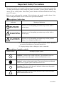
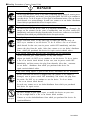
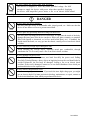
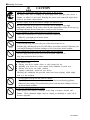
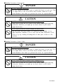
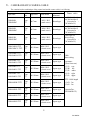
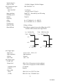
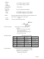
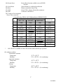
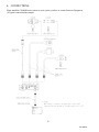
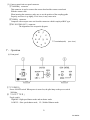
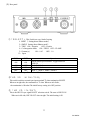
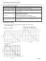
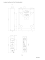
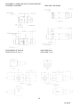
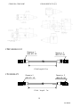
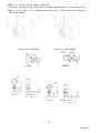
CCD B/W CAMERA
CS4000B/BC SERIES
OPERATION
MANUAL
Before using your CCD camera, please read this user's manual to become familiar with the correct usage
procedures. After reading, keep this manual in a safe place for future reference.
TOKYO ELECTRONIC INDUSTRY CO.,LTD.
This user's manual is manufactured from recycled paper.
D4119853A
Important Safety Precautions
The main unit and the user's manual of the product provide information on important contents that
will help prevent injury to those using the product and others, prevent property damage, and
ensure safe use of the product. Please make yourself familiar with this information before using
your CCD camera.
Make sure you understand the meaning of the indications and graphic symbols shown below
before reading this manual. Be sure to observe the precautions indicated.
● Description of indications
Indication
Meaning of indication
DANGER
Incorrect use or disregarding precautions may result in death or
serious injury
WARNING
Incorrect use or disregarding precautions may result in death or
serious injury
CAUTION
Incorrect use or disregarding precautions may result in personal
injury (*1) or damage to property (*2).
*1: Personal injury refers to injuries, burns, or electric shock that does
not require hospitalization or repeated hospital isits.
*2: Property damage refers to damage to assets or materials.
● Description of graphic symbols
Graphic symbol
Meaning of graphic symbol
Prohibited – actions to be avoided at all times. The prohibited actions are
indicated within or near the graphic symbol with illustrations or text.
Required – actions or that must be taken. The required actions are indicated
within or near a graphic symbol with illustrations or text.
Hazardous. The nature of the hazard is indicated within or near the graphic
symbol with illustrations or text.
Caution. The reason for the precaution indicated within or near the graphic
symbol with illustrations or text.
D4119853A
●Handling Precautions (Camera Control Unit)
DANGER
Unplug
Unplug
Unplug
Unplug
Unplug
NEVER
pull apart
If any overheating sign is observed, discontinue the use immediately.
In the event that smoke, smell, or any other overheating sign is observed, turn its power
switch OFF immediately, and remove your plug from outlet. Do NOT try to continue to
use this device. To do so in spite of clear signs of malfunction invites a fire, an electric
shock hazard, or a serious damage. In such case, contact us or our dealer /distributor
from which you purchased this device for repair service.
If any malfunctioning sign is observed, discontinue the use immediately.
Do NOT try to use this device when it is obviously malfunctioning. (Example: No
images on the monitor) In the event of malfunction, turn its power switch OFF
immediately, and remove the plug from the outlet. In such case, contact us or our dealer/
distributor from which you purchased this device for repair service.
If any liquid gets into the device, discontinue the use immediately.
In the event that water, or any other type of liquid gets into the body, do
NOT try to continue to use the device. To do so invites a fire or an electric
shock hazard. In that case, turn its power switch OFF immediately, and then
remove the plug from the outlet. After that, contact us or our dealer/ distributor
from which you purchased this device for repair service/technical advice.
If any foreign object gets into the body, discontinue the use immediately.
In the event that grits, small particles, or any other foreign
objects get inside, do NOT try to continue to use the device. To do so invites
a fire or an electric shock hazard. In that case, turn its power switch OFF
immediately, and then remove the plug from theoutlet. After that, contactus
or our dealer/ distributor from which you purchased this device for
repair service/technical advice.
If any outer strong impact is given to this device, discontinue the use immediately.
In the event that this device is dropped onto the ground, or its cabinet is
damaged, turn its power switch OFF immediately, and remove the plug from
the outlet. Do NOT try to continue to use the device. To do so invites
a fire or an electric shock hazard.
In such case, contact us or our dealer/distributor from which you purchased
this device for repair service.
Do NOT disassemble this device.
Do NOT attempt to pull apart, repair, or modify the device on your own.
To do so might lead to a fire or an electric shock accident.
Contact us or the dealer/distributor from which you purchased the device for
repair/modification.
D4119853A
Avoid
Do NOT supply any power other than specified.
This device is designed to work only under specified voltage. Do NOT
attempt to supply the device with power other than specified. Supplying
the device with unspecified power invites a fire or an electric shock hazard.
●Handling Precautions
DANGER
Avoid
Avoid
Avoid
Avoid
Avoid
Do NOT place the device unstably.
Do NOT place the device on an unstable table, sloped ground, etc.. Make sure that the
device do not fall nor roll over to prevent an accident.
Do NOT place any potentially-hazardous things on this device.
Do NOT place any things on the device which may, if it gets into the inside of the body,
damage the inner parts of the device (such as a flower pot, glass, cosmetics, a container
filled with liquids or chemicals, as well as small metal parts, etc.). If tumbled, the
liquids inside the bottle, etc. may get into the chassis, causing a fire or an electric shock
accident.
Do NOT insert any foreign object through air-vent
Avoid inserting any foreign object, especially metal part, combustible, through
ventilation slits. To do so may cause a fire or an electric shock accident.
Do NOT damage the power cord.
Do NOT damage, break, re-process, nor bend forcefully the power cord. Pulling
forcefully/Twisting/Placing a heavy object on/Applying heat on the cord should also be
avoided. Otherwise, the cord may be damaged, causing a fire or an electric shock
accident. If the cord is damaged, contact us or our dealer/distributor from which you
purchased this device for repair service.
Do NOT remove the protective cover
Avoid removing its protective cover. If you touch the inner high-voltage part, you might
get an electric shock. For inner part/circuit checkup, maintenance, or repair, contact us
or the dealer/distributor from which you purchased this device.
D4119853A
●Handling Precautions
CAUTION
Unplug
Avoid
Unplug the power-plug when the your device is not in use.
For safety, make sure to unplug the power-plug before you give your device a
cleanup, or when it is not used. Keeping the power-cord connected might invite
a fire or an electric shock hazard.
Do NOT expose your device to direct sunlight, nor intensive heat.
Do NOT place this device where it is exposed to direct sunlight, or in a high
temperature condition. To do so may cause the inner temperature of the device to go up,
resulting in burning-down of inner parts, circuits or a fire accident.
Avoid
Do NOT attempt to make connection before turning power off
Make sure to check the CCU power is OFF before connection.
Otherwise, you might get an electric shock.
Avoid
Do NOT pull the cord itself
When disconnecting the power-plug out of the outlet, make sure to
hold the plug, and then pull it out. Do NEVER try to pull the cord itself. Otherwise, the
cord may be damaged or broken, leading to a fire or an electric shock accident.
Avoid
Do NOT handle the power cord with your hand in an wet condition.
Do NOT plug in/out the power cord with an wet hand. Otherwise, it
may cause an electric shock accident.
Avoid
Avoid
Avoid
Do NOT block ventilating slits.
You should avoid;
n Placing your device upside down, or with wrong side up.
n Installing your device in a poor natural draft condition, recessed area.
n Placing your device on carpet, cushion.
n Putting a tablecloth, curtain on your device.
Blocking the ventilation slits prevents inner heat from escaping, which might
lead to a fire accident.
Do NOT place your device too close to a heater.
Do NOT place your device or its power cord too close to any heating appliance.
Otherwise, the coating of its switch and/or power-cord may melt, leading to a fire or
an electric shock accident.
Do NOT use chemical solvent for cleanup.
When giving your camera a cleanup, avoid using a benzene, alcohol, and
thinner. These chemicals might cause its coating or markings to come off or
become degraded.
D4119853A
●Handling Precautions (Camera-head)
DANGER
NEVER pull
apart
Do NOT disassemble this device.
Do NOT attempt to pull apart, repair, or modify the device on your own. Todo
so might lead to a fire or an electric shock accident. Contact us or the
dealer/distributor from which you purchased the device for repair/modification.
CAUTION
Avoid
Avoid
Do NOT connect/disconnect connectors before turning power off.
Make sure to check the CCU power is OFF before connecting/disconnecting
connectors. Otherwise, you might get an electric shock, or your camera
might break down.
Do NOT expose your device to direct sunlight, nor intensive heat.
Do NOT place this device where it is exposed to direct sunlight, or in a
high temperature condition. To do so may cause the inner temperature of the
device to go up, resulting in burning-down of inner parts, circuits or a fire
accident.
●Handling Precautions (Camera Cable)
DANGER
NEVER pull
apart
Do NOT disassemble this device.
Do NOT attempt to pull apart, repair, or modify the device on your own. To d
o so might lead to a fire or an electric shock accident. Contact us or the
dealer/distributor from which you purchased the device for repair/modification.
CAUTION
Avoid
Do NOT connect/disconnect connectors before turning power off.
Make sure to check the CCU power is OFF before connecting/disconnecting
connectors. Otherwise, you might get an electric shock, or your camera
might break down.
D4119853A
RESTRICTION FOR USE
1. Avoid irregular signal interface.
Do not attempt irregular signal interface other than specified. Under signal interface
other than recommended/specified in this instruction manual, the device might fail to
exert the maximum performance. In much worse case, if you continue to use your device
under incorrect signal interface, part(s) of inner circuits might burn down.
DISCLAIMER (LIMITED WARRANTY)
We disclaim any responsibility and shall be held harmless for damages or losses incurred by user(s) in
either of the following cases.
1. In case damages or losses are caused by fire, earthquake, or other acts of Gods, the act by third party,
misuse by the user deliberately or erroneously, use under extreme operating conditions.
2. In case any indirect, additional, consequential damages (loss of expected interest, suspension of
business activities) are incurred as results of malfunction or non-function of this device, we shall be
exempted from assuming responsibility for such damages.
3. In case damages or losses are caused by incorrect use which is not in line with the instructions given in
this instruction manual.
4.In case damages or losses are caused by malfunction resulting from bad connection with other
equipment.
5.In case damages or losses are caused by repair or modification done by the user.
OTHER INSTRUCTIONS
Do NOT use power other than specified
Be sure to use DC12V power supply. The camera is designed to work only under the specified voltage.
Do NOT attempt to drive the camera with the power other than DC12V. Operating the camera under
power other than DC12V invites a fire or a electric shock hazard.
Avoid intensive light
Do NOT expose the camera’s image-pickup-plane to sunlight or other intense light directly. If the part of
CCD is exposed to spot-intensive light, you might get a picture problem like blooming and/or smear. You
might observe vertical stripes on your monitor if your camera is exposed to sunlight (or any other
intensive light), however, this is not a malfunction. Redirect your CH (camera-head) to different
directions in such case.
Use under right operation condition
This equipment is designed and guaranteed to work under the temperature range of 0 to 40 degrees C and
30 through 90% humidity range. Avoid using the equipment beyond that limits.
Handle with care
Take care not to drop the equipment, nor give strong impact, as this may cause breakdown.
Do NOT tamper with switches
Read this operation guide thoroughly before you touch switches and adjusters on the rear panel. Do
NEVER attempt to disassemble the camera and/or tamper with any inner switches, potentiometers, etc.
D4119853A
Avoid liquid
Avoid placing the camera where it is likely to be splashed with water or any other fluids. Operating the
camera with its inner parts/circuits in an wet condition might cause a damage or an electric shock
accident.
About camera cable
The connector of the camera cable is in “screw-coupling” lock structure. Improper cramping might cause
image noise. Be sure to give it a good cramping to avoid noise.
Camera cable connection/disconnection
Before connecting/disconnecting connectors, make sure to turn camera power OFF. Otherwise, your
camera might break down.
Avoid placing near TV/radio
This camera might cause an interference (e.g. noise) if used around radio / TV set. In such a case, change
the location of your camera (or radio / TV).
Abnormal operation
In the event that any abnormal condition is observed, turn the power switch OFF immediately. Do NOT
try to continue to use the camera. To do so reckless of visible signs of malfunction invites a fire, an
electric shock hazard, or any other serious damage to the camera. In such case, contact us or our
dealer/distributor from which you purchased the camera for repair service.
Thank you for purchasing CS4000B series television camera featuring compact and light weight.
To take best advantage and gain the most service from your camera, read this operation manual
carefully and thoroughly.
WARNING:
TO PREVENT FIRE OR SHOCK HAZARD, DO NOT EXPOSE THIS APPLIANCE
TO RAIN OR MOISTURE.
This equipment should be used with DC12V. Do not use any other power source.
INFORMATION
This equipment generates and uses radio frequency energy and if not installed and used properly,
that is, in strict accordance with the manufacturer’s instructions, may cause interference to radio
and television reception. If does so, which can be determined by turning the equipment off and
on, the user is encouraged to try to correct the interference by one or more of the following
measures:
Reorient the receiving antenna;
Relocate this equipment with respect to the receiver;
Move this equipment away from the receiver;
If necessary, the user should consult the dealer or an experienced radio/television technician
for additional suggestions.
D4119853A
CONTENTS
Page
1. FEATURES
1
2. PRECAUTION
1
3. CAMERA HEAD&CAMARA CABLE
2
4. CONSTITUTION
3
5. SPECIFICATION
3
6. CONNECTIONS
8
7. OPERATION
9
8. TROUBLE-SHOOTING GUIDE
12
9. EXTERNAL VIEW
SPECTRUM RESPONSE
CAMERA CONTROL UNIT
CAMERA HEAD
CAMERA CABLE
HOW TO FIXED A LENS TO SQURE TYPE CAMERA HEAD
CAMERA MOUNTING KIT(OPTION)
D4119853A
1. FEATURES
(1) Compact and light weight camera head.
(2) Equipped with AGC (Automatic Gain Control) which allows wide dynamic range from bright to
dark subjects.
(3) Equipped with RTS (Random Trigger Shutter) which allows free timing capture with stable SYNC.
(4) Available external SYNC (HD/VD, VS, SYNC) operation.
2. PRECAUTION
(1) This equipment should be used with DC12V only.
To prevent electric shocks and fire hazards, do not use any other power source.
(2) The CS4000 series are designed to be used with EIA B/W television signals.
It cannot be used for playback with a television of a different standard
(3) Please handle the equipment carefully.
(4) Do not point your camera lens directly into sunlight or strong artificial light.
This might cause irreparable damage to the image sensor.
Also, be sure to use the lens cap when the camera is not in use.
(5) Do not expose the camera unit to high temperatures. For example, do not place it near a stove for
long periods, or in direct sunshine or in a car in hot weather. Heat may cause some malfunction.
(6) Keep the camera clean. Dust can damage the camera and cause trouble in moving parts.
Take particular care to avoid the entry of sand or grit when changing the camera lens.
(7) Avoid jolting the equipment or exposing it to vibration.
(8) Never attempt to dismantle the equipment.
(9) Avoid folding or stretching the camera cable or other connection cable between equipment.
(10) When the cabinet is dusty, clean by gently wiping with a soft cloth. And avoid the use of
strong cleaning agents such as benzene or alcohol as they may damage the cabinet.
1
D4119853A
3.CAMERA HEAD $ CAMERA CABLE
The constitution (the combinations of the camera head and the camera cable) is as following.
Camera Head
Type name
CCD
Size
CSH4200B
CSH4200BC
Type
1/2
CSH4300B
CSH4300BC
Type
1/3
CSH4301B
CSH4301BC
Appearance
Lens mount
φ17mm
M15.5 P0.5
(male screw)
φ12mm
M10.5 P0.5
(male screw)
Type
1/3
φ12mm
M10.5 P0.5
(male screw)
CSH4310BV-□□
CSH4310BCV-□□
Type
1/3
20×20mm
CSH4310BW-□□
CSH4310BCW-□□
Type
1/3
20×20mm
CSH4310BX-□□
CSH4310BCX-□□
Type
1/3
20×20mm
CSH4310BY-□□
CSH4310BCY-□□
Type
1/3
20×20mm
CSH4310BZ-□□
CSH4310BCZ-□□
Type
1/3
20×20mm
CSH4410BW-□□
Type
1/4
20×20mm
CSH4410BX-□□
Type
1/4
20×20mm
CSH4410BY-□□
Type
1/4
20×20mm
CSH4410BZ-□□
Type
1/4
20×20mm
M10.5 P0.5
(female screw)
M10.5 P0.5
(female screw)
M10.5 P0.5
(female screw)
M10.5 P0.5
(female screw)
M10.5 P0.5
(female screw)
M10.5 P0.5
(female screw)
M10.5 P0.5
(female screw)
M10.5 P0.5
(female screw)
M10.5 P0.5
(female screw)
Appearance of the
camera head
Camera cable
Round type
3m(CPRC4000B-03)
5m(CPRC4000B-05)
Extension7m :
(CPC4000B-07J)
Round type
3m(CPRC4000B-03)
5m(CPRC4000B-05)
Extension7m :
(CPC4000B-07J)
Round type
Cable length 3m
(Direct wiring)
Extension7m
(CPC4000B-07J)
:
Square type
Square type
Cable:
Direct wiring
Square type
Type name:
(view from rear)
(1) V: rear
(2) W: left
(3) X: under
(4) Y: right
(5) Z: upper
Square type
Square type
Square type
□□:・Cable length
(1) 03:3m
(2) 05:5m
Square type
Extension7m:
(CPC4000B-07J)
Square type
Square type
2
D4119853A
4.CONSTITUTION
(1)
(2)
(3)
Camera control unit
1
Accessories
Operation manual
1
Option
① Each camera head
② Camera cable:CPRC4000B-03(3m),-05(5m)
③ Extension camera cable:CPC4000B-07J(7m)
④ Power adapter:CA130C-01
⑤ Power cable(Both ends 12P connector):3m, 5m, 10m
⑥ Cable for power supply(VIDEO,HD,VD,SYNC,WENOUT、TRIGINPUT)
⑦ Lens
⑧ For DC INPUT CONNECTOR
⑨ C mount Adapter
About the option part and EMC
This camera guarantee combination with option part .
EMC is not guarantee incase with use non-designate option part.
5.SPECIFICATIONS
(The FACTOR is combination CSH4200B with 3m camera cable when no display head type.)
(1) TV system
B type
EIA
BC type
CCIR
(2) Image sensor
Interline CCD
(CSH4200B)
ICX418ALB
(CSH4200BC )
ICX419ALB
(CSH4301B)
ICX408ALB
(CSH4301BC )
ICX409ALB
(CSH4310B□-□□)
ICX408AL
(CSH4310BC□-□□)
ICX409AL
(CSH4410B□-□□)
ICX228AL
・Total Active pixel
(EIA)/ (CCIR)
811(H)×508(V) / 795(H)×596(V)
・Active pixel
(EIA)/ (CCIR)
768(H)×494(V) / 752(H)×582(V)
・Video out Active pixel
(EIA)/ (CCIR)
756(H)×485(V) / 742(H)×575(V)
・Pixel Size
(CSH4200B)
8.4×9.8μm
(CSH4200BC )
8.6×8.3μm
(CSH4301B、CSH4310B□-□□) 6.35×7.4μm
(CSH4301BC、CSH4310BC□-□□)6.5×6.25μm
3
D4119853A
(CSH4401B□-□□)
4.75×5.55μm
・Active image area
(CSH4200B,CSH4200BC)
6.5×4.85mm(1/2Type)
(CSH4301B、CSH4310B□-□□)
4.8×3.6mm(1/3Type)
(CSH4301BC、CSH4310BC□-□□)
(CSH4401B□- □□)
3.65×2.74mm(1/4Type)
(3) Number of scanning lines
(EIA)/ (CCIR)
525 lines / 625 lines
(4) Scanning system
2 : 1 interlace
(5) Sync .System
Internal/External automatic switch-over
(6) Aspect ratio
4:3
(7) Illumination
・Standard
(CSH4200B,CSH4200BC)
100lx F5.6
(CSH4301B、CSH4310B□-□□
150lx F5.6
CSH4301BC、CSH4310BC□-□□)
(CSH4401B□-□□)
300lx F5.6
GAIN:STD γ=1.0
・Minimum
(CSH4200B, CSH4200BC)
0.5lx F5.6
(CSH4301B、CSH4310B□-□□ 0.7lx F5.6
CSH4301BC、CSH4310BC□-□□)
(CSH4401B□-□□)
1.5lx F5.6
GAIN:MAX、γ=0.45
(8) Video output
VS=1.0 V(p-p)/75Ω,1line
DC/AC coupling (inner SW setting)
(9) Resolution
(EIA)
H:570TVlines , V:485TVlines
(CCIR )
H:560TVlines , V:575TVlines
(10) GAIN control
AUTO/STD/MANU (Front panel SW setting)
Video level can be adjustable by「GAIN」
Potentiometer when MANU.
(11) Gamma
ON(0.45)/OFF(1.0)Selectable by rear DIPSW setting
Initial factory setting: OFF(1.0)
(12) White clip
clip-level 857±40mV(p-p):SYNC non-include
(13) S/N
50dB(p-p)/rms(standard) (GAIN=STD,γ=1.0)
(14) CCD integration mode
Field/Frame storage (integration) by rear DIPSW setting
Initial factory setting: Field storage integration
(15) Power source
DC12V±10%(Ripple level: Less than10mV(p-p)
(16) Power consumption
approx.400mA(DC12V)
(17) Scanning frequencies
(Internal synchronization mode)
・Horizontal drive(H)
(EIA) /(CCIR)
14.31818MHz±100ppm/ 14.18750MHz±100ppm
4
D4119853A
・Vertical drive(V)
(EIA) /(CCIR)
(18) External sync input
・Input level
HD・VD,SYNC
VS
・Input impedance
・Scanning system
・Polarity
・Frequency
(EIA)
(CCIR)
・Scanning lines
(EIA) /(CCIR)
・Phase different
59.94Hz±100ppm/ 50.0Hz±100ppm
HD・VD/SYNC/ VS
2∼6V(p-p)
1.0V(p-p) (Sync:0.3V(p-p))
High/75Ω 、Selectable by rear SW setting
2:1 interlace
Negative
fH =15.734kHz±1%, fV =2fH/525
fH =15.625kHz±1%, fV =2fH/625
525lines/ 625lines
The difference in phase between the falling edge of VD
and that of HD is shown in the figure below.
1st field for EIA
2nd Field for EIA
2nd FIELD for EIA
1st Field for CCIR
VD
HD
t1
t1=0±5μs
(19) Trigger input
・Input level
・Input impedance
・Polarity
・Pulse with
(20) Output signal
① HD・VD
・Output level
・Scanning system
・Polarity
・Pulse width
(EIA)
(CCIR )
t2
t2=1/fH/2±5μs
VL=0∼0.5V、 VH=2∼5V
High impedance
Negative
2μs∼1/4s
HD:4.5V±0.5V(p-p)(on no-load condition)
VD:5.0V±0.5V(p-p)(on no-load condition)
2:1 interlace
Negative
HD:6.36±1μs, VD:572±10μs
HD:6.41±1μs, VD:480±10μs
5
D4119853A
・Frequency
(EIA)
(CCIR )
・Scanning line
(EIA) /(CCIR)
② CLOCK
・Output level
・Frequency
(EIA)
(CCIR )
③WEN
・Polarity
・Diagram
fH:15.334kHz±100ppm, fV:2fH/525
fH:15.625kHz±100ppm, fV:2fH/625
525line/ 625line
2.0±0.3V(p-p)(on no-load condition)
14.31818MHz±100ppm(on no-load condition)
14.18750MHz±100ppm(on no-load condition)
On operate random shutter mode, WEN put out from the fall time of VD
to the fall time of VD under put out video signal..
Positive
The circuit is shown in the figure below
51
WEN
4700
10k
(21) Electronic shutter
Shutter speed can set by front panel switch
As follow:
OFF,1/125,1/250,1/500,1/1000,1/2000,
1/4000,1/10000, flickerless
1FLD,2FLD,4FLD,6FLD,8FLD,10FLD
(slow speed shutter mode)
(22) Random shutter
RTS mode selection available
Mode1
Mode2
Mode3
Mode4
Mode5
Mode6
Mode7
Mode8
(23) Special shutter
2SC4176
Shutter-speed switch setting
Shutter-speed switch setting
Shutter-speed switch setting
Shutter-speed switch setting
Shutter-speed switch setting
Shutter-speed switch setting
Shutter-speed switch setting
Shutter-speed switch setting
Internal sync
Internal sync
Internal sync
Internal sync
SeriesHD,SeriesVDinput
SeriesHD,SeriesVDinput
SeriesHD,One-pulseVDinput
SeriesHD,One-pulseVDinput
SYNC non-reset
SYNC non-reset
SYNC Reset
SYNC Reset
SYNC non-reset
SYNC non-reset
SYNC non-reset
SYNC non-reset
Usr-defined shutter-speed cued and timed by shutter
trigger and restart / reset pulse input ON /OFF
selectable via rear panel DIP SW.
(Initial factory setting :OFF)
6
D4119853A
(24) Restart Reset
Restart Reset function available via rear DIP SW
selection.
Special Mount, by each head specification.
Camera control unit: about 350g
Circuit GND---Chassis: Electrically continuous
Conforms to EN50081-2
(25) Lens Mount
(26) Mass
(27) GND
(28) EMI
(29) Connector Pin Assignment
・Power/Video connector
・Compatible plug :HR10A-10P-12S(Manufactured HIROSE ELEC)
Pin
External sync
Internal sync
No.
HD・VD
VS/SYNC
Restart Reset
1
GND
GND
GND
GND
2
+12V
+12V
+12V
+12V
3
GND
GND
GND
GND
4
Video OUT
Video OUT
Video OUT
Video OUT
5
GND
GND
GND
GND
6
HD INPUT
HD INPUT
HD OUT (*1)
7
VD INPUT
VS/SYNC
R.R INPUT
VD OUT (*1)
INPUT
8
GND
GND
GND
GND
9
CLOCK OUT
CLOCK OUT
CLOCK OUT
CLOCK OUT
10
WEN OUT
WEN OUT
WEN OUT
11
TRIG INPUT
TRIG INPUT
TRIG INPUT
TRIG INPUT
12
GND
GND
GND
GND
*1
HD・VD OUT is available via inner SW selection under internal sync operation.
(30) Ambient condition
・Performance assurance
Temperature
Humidity
・Operation assurance
Temperature
Humidity
・Storage
Temperature
Humidity
0℃∼40℃
20∼80% (No condensing)
-10℃∼50℃
20∼80% (No condensing)
-20℃∼60℃
20∼95% (No condensing)
7
D4119853A
6.CONNECTIONS
When install the CS4000B series camera to your system, you have to connect between Equipment.
(1)Typical connection(One sample)
8
D4119853A
(2) Camera control unit rear panel connector
①「CAMERA」 connector
This connector is used to connect the camera head and the camera control unit
With the camera cable.
When inserting the connector, make sure to set the position of the coupling-guide
Properly, and screw it up tightly, If it is loose, it may cause noise.
②「VIDEO」 connector
Composite video output come out from this connector which is employed BNC type.
③「DC IN/VIDEO OUT」 connector
The alignment of the receptacle dip posts
①
②
⑨
⑪
③
④
⑧
⑩
⑫
⑦
⑥
⑤
12terminals(male)
(rear view)
7.Operation
(1) Front panel
①「POWER」
Power ON/OFF switch. When power is turned on, the pilot lamp on the power switch
Will light.
② 「SHUTTER」
・Toggle switch
High/OFF: High speed shutter mode and no shutter mode.
LOW/F/L : Slow speed shutter mode, FL, Width of Shutter mode.
9
D4119853A
・Rotary switch
(When set the toggle switch to High/OFF)
0:Shutter off
1:1/125s
2:1/250s
3:1/500s
4:1/1,000s
5:1/2,000s
6:1/4,000s
7:1/10,000s
(When set the toggle switch to LOW/F.L)
0:FL(flickerless)
1:1/60(CCIR:1/50)
2:2FLD
3:4FLD
4:6FLD
5:8FLD
6:10FLD
7:① setting of pulse width
② Rear panel switch SMD1:ON, SMD2:ON
Restart Reset operation/ special shutter ・ reset operation
③ 「GAIN CONTROL」
・AUTO
When AGC (Automatic Gain Control) is to increase or decrease sensitivity electrically to
get the comfortable video level.
・STD
Normally, put it [STD] position. The gain is fixed.(0dB)
・MANU
If the illumination of the subject is not sufficient and the picture on the monitor is dark or
bright, set this switch to [MANU] position. And you can adjust the video level with the
knob of [GAIN].
10
D4119853A
(2) Rear panel
① 「SELECT」:This Switch set every kind of setting.
1:SMD1(Setting about Shutter mode)
2:SMD2(Setting about Shutter mode)
3:TRIG ON:Negative
OFF:Positive
4:Ccd integration mode ON:FIELD OFF:FLAME
5:Gamma(γ)
ON:0.45
OFF:1.0
6:Open
SMD1
SMD2
Operation
Restart・Reset/Special shutter: Toggle switch set
ON
ON
LOW/F.L
ON
OFF
Mode 7, Mode 8
OFF
ON
Mode 3, Mode 4
OFF
OFF
Mode 1,Mode 2, Mode 5, Mode 6
*Refer to shutter specification about Mode.
②「HD VD
HIGH/75Ω」
This switch switches external-sync input terminal 75-ohm termination ON/OFF.
When set in right side, the termination is 75-ohm. When set in left side,
the termination is 10k-ohm.The initial factory setting is in OFF position.
③ 「HD VD IN/OUT」
This is the HD VD sync-signal IN/OUT selection switch. The state is HD VD IN
When set in left side, HD VD OUT when in right. The initial setting is IN.
11
D4119853A
8.TROUBLE-SHOOTING GUIDE
What may initially appear to be trouble is not always a real problem. Make sure first according to the
following table before requesting service.
Symptoms
Check points
Power: No power is supplied
* Have you connected power cord correctly ?
Halation or black-out occurs
*Check whether the iris ring has accidentally moved out of the
normal position.
No picture
*Is it extremely dark on subjects?
*Improper connection or setting.
*Do other system equipments work properly?
*Are the connection cables between equipments properly?
Halation or black-out occurs
*Check whether the iris ring has accidentally moved out of the
normal position.
9.EXTERNAL VIEW
Typical spectral response (The lens characteristics and light source characteristics
Is not reflected in table.)
CSH430□B, CSH4310B□-□□
CSH4200B、 CSH4200BC
CSH430□BC、 CSH4310BC□-□□
CSH4410B□-□□
12
D4119853A
CAMERA CONTROL UNIT OUTLINE DRAWING
13
D4119853A
CS4000B/BC CAMERA HEAD OUTLINE DRAWING
CSH4200B, CSH4200BC
CSH4310BW/X/Y/Z/X-□□
CSH4310CW/X/Y/Z-□□
CSH4300B, CSH4300BC
CSH4310BV-□□
CSH4310BCV-□□
14
D4119853A
CSH4301B, CSH4301BC
CSH4410BW/X/Y/Z-□□
CPRC4000B-03/05
Connector 1
HR25-8TP-14S
Connector 2
HR25-9TP-16P
Cable length 3/5 m
CPC4000B-07J
Connector1
HR25-9TJ-16S
Connector 2
HR25-9TP-16P
Cable length 7m
15
D4119853A
[HOW to fix a lens to this square type head]
To prevent loosing of the lens from the camera head because of some vibration or
Shock, fix the lens to this camera head with tightly. The screw is provided with
This camera head.
Mount kit:CSH4200B/BC
Mount kit: CSH4300B/BC
16
D4119853A
NOTE
17
D4119853A
18
D4119853A
TOKYO ELECTRONIC INDUSTRY CO.,LTD.
Sales Department Head Office:
7-1, Asahigaoka 4-chome, Hino city, Tokyo 191-0065, Japan.
Phone:042(589)8771
Fax:042(589)8774
Kansai Office:
1-2, Sakaemachi-dori 2-chome, Chuo-ku, Kobe city 650-0023, Japan.
Phone:078(321)3461
Fax:078(321)3463
Fukuoka Office:
7-21, Hirao 3-chome, Chuo-ku, Fukuoka city 810-0014, Japan.
Phone:092(523)3395
Fax:092(523)3397
D4119853A