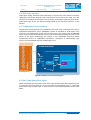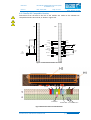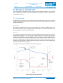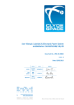
1
USM-0002
User Manual: FleXible Electronic Power System:
CS-XUEPS2-41/-42
Issue: D
Date: 26/02/2015
Page: 2 of 44
5B, Skypark 5, 45 Finnieston
Street, Glasgow, G3 8JU
Document Control
Issue
Date
Section
Description of Change
Reason for Change
A
22/07/10
All
First Draft
N/A
B
30/07/2010
Revision Control
Rev B onwards only
11.4
ADC conversion Equations
Updated
Telemetry equation
changes
Improvement of telemetry
circuit accuracy
C
19/01/2015
11.2 and 11.3
Section 11.2 and 11.3
minor updates
Readability
D
26/02/2015
Several
Updates throughout to
being in line with current
build standard
Updated hardware build
standard
Part Number
Revisions covered
Notes
Revision Control
Product
Cubesat FleXible
Power System
Electronic
CS-XUEPS2-42
B
4 Large BCRs, 2 Small BCRs
Cubesat FleXible
Power System
Electronic
CS-XUEPS2-41
E
4 Large BCRs, 1 Small BCR
Acronyms and Abbreviations
BCR
Battery Charge Regulator
PCM
Power Conditioning Module
PDM
Power Distribution Module
MPPT
Maximum Power Point Tracker
USB
Universal Serial Bus
ESD
Electro Static Discharge
TLM
Telemetry
EPS
Electrical Power System
EoC
End of Charge
AMUX
Analogue Multiplexer
ADC
Analogue to Digital Converter
AIT
Assembly, Integration and Testing
1U
1 Unit (Cubesat standard size)
3U
3 Unit (Cubesat standard size)
FleXU/XU
FleXible Unit (suitable for various satellite configurations)
rh
Relative Humidity
Wh
Watt Hour
Ah
Ampere Hour
DoD
Depth of Discharge
Kbits-1
Kilobits per second
Voc
Open Circuit Voltage
Isc
Short Circuit Current
2s1p
Battery configuration – 2 cells in series, 1 battery in parallel (single string)
2s2p
Battery configuration – 2 cells in series, 2 batteries in parallel
2s3p
Battery configuration – 2 cells in series, 3 batteries in parallel
SOLUTIONS FOR A NEW AGE IN SPACE
PROPRIETARY & CONFIDENTIAL INFORMATION
www.clyde-space.com
© Clyde Space Limited 2015
USM-0002
Issue: D
User Manual: FleXible Electronic Power System:
CS-XUEPS2-41/-42
5B, Skypark 5, 45 Finnieston
Street, Glasgow, G3 8JU
Date: 26/02/2015
Page: 3 of 44
No.
Document Name
Doc Ref.
RD-1
Battery board User Manual
TBC
RD-2
CubeSat Design Specification
CubeSat Design Specification Rev. 12
RD-3
NASA General Environmental
Verification Standard
GSFC-STD-7000 April 2005
RD-4
CubeSat Kit Manual
UM-3
RD-5
Solar Panel User Document
Power System Design and
Performance on the World’s
Most Advanced In-Orbit
Nanosatellite
TBC
Related Documents
RD-6
#
Warning
As named
Risk
Ensure headers H1 and H2 are correctly aligned
before mating boards
If misaligned, battery positive can short to
ground, causing failure of the battery and EPS
Ensure switching configuration is implemented
correctly before applying power to EPS
If power is applied with incorrect switch
configuration, the output of the BCR can be
blown, causing failure of the EPS and
subsequent damage to the battery
Observe ESD precautions at all times
The battery is a static sensitive system. Failure
to observe ESD precautions can result in failure
of the battery
Ensure not to exceed the maximum stated limits
Exceeding any of the stated maximum limits can
result in failure of the battery
Ensure batteries are fully isolated during
storage
If not fully isolated (by switch configuration or
separation) the battery may over-discharge,
resulting in failure of the battery
No connection should be made to H2.35-36
These pins are used to connect the battery to
the EPS. Any connections to the unregulated
battery bus should be made to pins H2.43-44
H1 and H2 pins should not be shorted at any
time
These headers have exposed live pins which
should not be shorted at any time. Particular
care should be taken regarding the surfaces
these are placed on.
8
Battery should only be operated when
integrated with an EPS
The EPS includes a number of protection circuits
for the battery. Operation without these
protections may lead to damage of the batteries
9
Do not discharge batteries below 6V
If the battery is discharged to a voltage below
6V the cells have been compromised and will no
longer hold capacity
If batteries are over-discharged DO NOT
attempt to recharge
If the battery is over discharged (below 6V) it
should not be recharged as this may lead to cell
rupture.
10
10
SOLUTIONS FOR A NEW AGE IN SPACE
PROPRIETARY & CONFIDENTIAL INFORMATION
www.clyde-space.com
© Clyde Space Limited 2015
USM-0002
Issue: D
1.
User Manual: FleXible Electronic Power System:
CS-XUEPS2-41/-42
Date: 26/02/2015
Page: 4 of 44
5B, Skypark 5, 45 Finnieston
Street, Glasgow, G3 8JU
Introduction .......................................................................................................................... 6
1.1
Additional Information Available Online ............................................................................................6
1.2
Continuous Improvement ...................................................................................................................6
1.3
Document Revisions ...........................................................................................................................6
2.
Overview ............................................................................................................................... 7
3.
Maximum Ratings(1) .............................................................................................................. 8
4.
Electrical Characteristics ....................................................................................................... 9
5.
Handling and storage .......................................................................................................... 10
5.1
Electro Static Discharge (ESD) Protection .........................................................................................10
5.2
General Handling ..............................................................................................................................10
5.3
Shipping and Storage ........................................................................................................................10
6.
Materials and Processes ..................................................................................................... 11
6.1
Materials Used ..................................................................................................................................11
6.2
Processes and Procedures ................................................................................................................11
7.
System Description ............................................................................................................. 12
7.1
System Overview ..............................................................................................................................13
7.2
Autonomy and Redundancy .............................................................................................................14
7.3
Quiescent Power Consumption ........................................................................................................14
7.4
Mass and Mechanical Configuration ................................................................................................14
8.
Interfacing........................................................................................................................... 15
8.1
Connector Layout .............................................................................................................................15
8.2
Solar Array Connection .....................................................................................................................16
8.3
Solar Array Harness ..........................................................................................................................19
8.4
Temperature sensing interface.........................................................................................................19
8.5
Non-Clyde Space Solar Arrays ...........................................................................................................19
8.6
CubeSat Kit Compatible Headers ......................................................................................................20
8.7
Cubesat Kit Header Pin Out ..............................................................................................................21
8.8
Switch Options ..................................................................................................................................23
8.9
Battery connection ...........................................................................................................................25
8.10
Buses.................................................................................................................................................25
9.
Technical description .......................................................................................................... 26
9.1
Charge Method .................................................................................................................................26
9.2
BCR Power Stage Overview ..............................................................................................................27
9.3
MPPT ................................................................................................................................................27
9.4
5V and 3.3V PCM ..............................................................................................................................28
10.
General protection ............................................................................................................. 29
10.1
Over-Current Bus Protection ............................................................................................................29
10.2
Battery Under-voltage Protection ....................................................................................................30
11.
11.1
Telemetry and Telecommand ............................................................................................. 31
I2C Node ............................................................................................................................................31
SOLUTIONS FOR A NEW AGE IN SPACE
PROPRIETARY & CONFIDENTIAL INFORMATION
www.clyde-space.com
© Clyde Space Limited 2015
USM-0002
Issue: D
User Manual: FleXible Electronic Power System:
CS-XUEPS2-41/-42
Date: 26/02/2015
Page: 5 of 44
5B, Skypark 5, 45 Finnieston
Street, Glasgow, G3 8JU
11.2
Command Summary .........................................................................................................................33
11.3
ADC Channels and Conversion Equations .........................................................................................35
12.
Test ..................................................................................................................................... 37
12.1
Power up/Down Procedure ..............................................................................................................37
12.2
Solar Array Input ...............................................................................................................................38
12.3
Battery Setup ....................................................................................................................................39
12.4
Configuration and Testing ................................................................................................................39
13.
Developer AIT ..................................................................................................................... 42
14.
Compatible Systems ........................................................................................................... 44
SOLUTIONS FOR A NEW AGE IN SPACE
PROPRIETARY & CONFIDENTIAL INFORMATION
www.clyde-space.com
© Clyde Space Limited 2015
USM-0002
User Manual: FleXible Electronic Power System:
CS-XUEPS2-41/-42
Issue: D
Date: 26/02/2015
5B, Skypark 5, 45 Finnieston
Street, Glasgow, G3 8JU
Page: 6 of 44
1. INTRODUCTION
This document provides information on the features, operation, handling and storage of
the Clyde Space FleXU EPS. The FleXU EPS has been designed to be flexible to your
satellite’s power requirements, providing four ‘large’ BCRs (for 4-8 cell solar panel pairs)
and either one, or two ‘small’ BCRs (for 2 cell solar panel pairs). The FleXU EPS will
integrate with a suitable battery and solar arrays to form a complete power system for
use on a CubeSat or Nanosat.
EPS
BCR1
Over Current
Protection
12W
Ideal
Diode
BCR2
BCR_OUT
PCM_IN
12W
3.3V
REG
Switch
Configuration
As Defined By
User
12W
BCR3
BCR4
USB
+5V
5V
REG
2
i c node
3W 12W
TELEMETRY
BCR5
BCR6*
BATT_POS
3W
2
i c node
TELEMETRY
CLYDE SPACE 3U BATTERY
* BCR6 only on CS-XUEPS2-42 and CS-XU-EPS2-42A
Figure 1-1 System Diagram
1.1 Additional Information Available Online
Additional information on CubeSats and Clyde Space Systems can be found at www.clydespace.com. You will need to login to our website to access certain documents.
1.2 Continuous Improvement
At Clyde Space we are continuously improving our processes and products. We aim to
provide full visibility of the changes and updates that we make, and information of these
changes can be found by logging in to our website: http://www.clyde-space.com.
1.3 Document Revisions
In addition to hardware and software updates, we also make regular updates to our
documentation and online information. Notes of updates to documents can also be found
at www.clyde-space.com.
SOLUTIONS FOR A NEW AGE IN SPACE
PROPRIETARY & CONFIDENTIAL INFORMATION
www.clyde-space.com
© Clyde Space Limited 2015
USM-0002
Issue: D
User Manual: FleXible Electronic Power System:
CS-XUEPS2-41/-42
Date: 26/02/2015
Page: 7 of 44
5B, Skypark 5, 45 Finnieston
Street, Glasgow, G3 8JU
2. OVERVIEW
This is the second generation of Clyde Space CubeSat Electronic Power System, developed
by our team of highly experienced Spacecraft Power Systems and Electronics Engineers.
Since introducing the first generation in 2006, Clyde Space has shipped over 120 EPS and
Batteries to a variety of customers in Europe, Asia and North America. The second
generation EPS builds on the heritage gained with the first generation, whilst increasing
power delivery capability by approximately 50%. Furthermore, we have implemented an
ideal diode mechanism, which ensures that there will be zero draw on the battery in
launch configuration.
Clyde Space is the World leading supplier of power system components for CubeSats. We
have been designing, manufacturing, testing and supplying batteries, power system
electronics and solar panels for space programmes since 2006. Our customers range from
universities running student led missions, to major space companies and government
organisations.
SOLUTIONS FOR A NEW AGE IN SPACE
PROPRIETARY & CONFIDENTIAL INFORMATION
www.clyde-space.com
© Clyde Space Limited 2015
USM-0002
User Manual: FleXible Electronic Power System:
CS-XUEPS2-41/-42
Issue: D
Date: 26/02/2015
5B, Skypark 5, 45 Finnieston
Street, Glasgow, G3 8JU
Page: 8 of 44
3. MAXIMUM RATINGS(1)
OVER OPERATING TEMPERATURE RANGE (UNLESS OTHERWISE STATED)
4
BCR
Value
Unit
SA1 (pin 1 or pin 4)
BCR1 (12W)
25
V
SA2 (pin 1 or pin 4)
BCR2 (12W)
25
V
SA3 (pin 1 or pin 4)
BCR3 (12W)
25
V
SA4 (pin 1 or pin 4)
BCR4 (12W)
25
V
SA5 (pin 1 or pin 4)
BCR5 (3W)
10
V
SA6 (pin 1 or pin 4)(3)
BCR6 (3W)
10
V
Battery
8.3
V
5V Bus
5.05
V
3.3V Bus
3.33
V
Notes
Value
Unit
BCR1-4
@16V
750
mA
BCR5-6(3)
@6V
750
mA
Battery Bus
@8.26V
6
A
5V Bus
@5V
4
A
3.3V Bus
@3.3V
4
A
Operating Temperature
-40 to +85
°C
Storage Temperature
-50 to +100
°C
Vacuum
10-5
torr
Radiation Tolerance
(TBC)
kRad
Shock
(TBC)
Vibration
To [RD-3]
Input Voltage(2)
Input Current
Output Current
Table 3-1 Max Ratings of the FleXU EPS2
(1)
Stresses beyond those listed under maximum ratings may cause permanent damage to the EPS. These are the
stress ratings only. Operation of the EPS at conditions beyond those indicated is not recommended. Exposure
to absolute maximum ratings for extended periods may affect EPS reliability
(2)
De-rating of power critical components is in accordance with ECSS guidelines.
(3)
BCR 6 only available on CS-XUEPS2-42
SOLUTIONS FOR A NEW AGE IN SPACE
PROPRIETARY & CONFIDENTIAL INFORMATION
www.clyde-space.com
© Clyde Space Limited 2015
USM-0002
User Manual: FleXible Electronic Power System:
CS-XUEPS2-41/-42
Issue: D
Date: 26/02/2015
Page: 9 of 44
5B, Skypark 5, 45 Finnieston
Street, Glasgow, G3 8JU
4. ELECTRICAL CHARACTERISTICS
Description
Conditions
Min
Typical
Max
Unit
7.4
--
25
V
Output Voltage
6.2
--
8.26
V
Output Current
0
--
1.2
A
245
250
255
KHz
85%
90%
92%
3.5
--
8(1)
V
Output Voltage
6.2
--
8.26
V
Output Current
0
--
0.5
A
160
170
180
KHz
77%
79%
80%
Output Voltage
6.2
--
8.26
V
Output Current
--
4
4.2
A
Operating Frequency
--
--
--
98.5%
99%
99.5%
12W BCR (1-4)
Input Voltage
Switching Frequency
Efficiency
@16.5V input, Full Load
3W BCR (5-6)
Input Voltage
Operating Frequency
Efficiency
@6V input, Full Load
Unregulated Battery Bus
Efficiency
@8.26V input, Full Load
5V Bus
Output Voltage
4.95
5
5.05
V
Output Current
--
4
4.2
A
470
480
490
kHz
95%
96%
98%
3.276
3.3
3.333
V
Output Current
--
4
4.2
A
Operating Frequency
470
480
490
kHz
94%
95%
97%
Protocol
--
I2C
--
Transmission speed
--
100
400
Operating Frequency
Efficiency
@5V input, Full Load
3.3V Bus
Output Voltage
Efficiency
@3.3V input, Full Load
Communications
Bus voltage
3.26V
3.3V
3.33V
Node address
--
0x2B
--
Address scheme
--
7bit
--
Node operating frequency
--
8MHz
--
KBps
Hex
Quiescent Operation
Power Draw
Flight
Configuration
Switches
of
--
--
<0.1
L
W
H
Height from top of PCB to
bottom of next PCB in stack
95
90
15.24
mm
CS-XUEPS2-41
130
133
136
g
CS-XUEPS2-42
134
137
140
G
Physical
Dimensions
Weight
W
Table 4-1 Performance Characteristics of the FleXU EPS2
(1)
BCR6 can tolerate inputs of up to 9.18V on CS-XUEPS2-42A variant
SOLUTIONS FOR A NEW AGE IN SPACE
PROPRIETARY & CONFIDENTIAL INFORMATION
www.clyde-space.com
© Clyde Space Limited 2015
USM-0002
User Manual: FleXible Electronic Power System:
CS-XUEPS2-41/-42
Issue: D
Date: 26/02/2015
Page: 10 of 44
5B, Skypark 5, 45 Finnieston
Street, Glasgow, G3 8JU
5. HANDLING AND STORAGE
The EPS requires specific guidelines to be observed for handling, transportation and
storage. These are stated below. Failure to follow these guidelines may result in damage
to the units or degradation in performance.
5.1 Electro Static Discharge (ESD) Protection
3
The EPS incorporates static sensitive devices and care should be taken during handling.
Do not touch the EPS without proper electrostatic protection in place. All work carried out
on the system should be done in a static dissipative environment.
5.2 General Handling
The EPS is designed to be robust and able to withstand flight conditions. However, care
must be taken when handling the device. Do not drop the device as this can damage the
EPS. There are live connections between the battery systems and the EPS on the CubeSat
Kit headers. All metal objects (including probes) should be kept clear of these headers.
Gloves should be worn when handling all flight hardware.
Flight hardware should only be removed from packaging in a class 100000 (or better) clean
room environment.
5.3 Shipping and Storage
The devices are shipped in anti-static, vacuum-sealed packaging, enclosed in a hard
protective case. This case should be used for storage. All hardware should be stored in
anti-static containers at temperatures between 20°C and 40°C and in a humiditycontrolled environment of 40-60%rh.
The shelf-life of this product is estimated at 5 years when stored appropriately.
SOLUTIONS FOR A NEW AGE IN SPACE
PROPRIETARY & CONFIDENTIAL INFORMATION
www.clyde-space.com
© Clyde Space Limited 2015
USM-0002
User Manual: FleXible Electronic Power System:
CS-XUEPS2-41/-42
Issue: D
Date: 26/02/2015
5B, Skypark 5, 45 Finnieston
Street, Glasgow, G3 8JU
Page: 11 of 44
6. MATERIALS AND PROCESSES
6.1 Materials Used
Material
Manufacturer
%TML
%CVCM
%WVR
Application
1.
Araldite 2014 Epoxy
Huntsman
0.97
0.05
0.33
Adhesive fixing
2.
1B31 Acrylic
Humiseal
3.89
0.11
0.09
Conformal
Coating
3.
DC 6-1104
Dow Corning
0.17
0.02
0.06
Adhesive fixing
on modifications
4.
Stycast 4952
Emerson &
Cuming
0.42
0.17
0.01
Thermally
Conductive RTV
5.
PCB material
FR4
0.62
0
0.1
Note: worst case
on NASA outgassing list
6.
Solder Resist
CARAPACE
EMP110 or
XV501T-4
0.95
or 0.995
0.02
Or 0.001
0.31
-
7.
Solder
Sn62 or Sn63
(Tin/Lead)
-
-
-
-
8.
Flux
Alpha Rosin
Flux, RF800,
ROL 0
-
-
-
Note: ESA
Recommended
Table 6-1 Materials List
Part Used
Manufacturer
Contact
Insulator
Type
Use
DF13-6P-1.25DSA(50)
Hirose
Gold Plated
Polyamide
PTH
Solar Array
Connectors
ESQ-126-39-G-D
Samtec
Gold Plated
Black Glass Filled
Polyester
PTH
CubeSat Kit
Compatible
Headers
DF13-6S-1.25C
Hirose
N/A
Polyamide
Crimp Housing
Harness for Solar
Arrays (sold
separately)
DF13-2630SCFA(04)
Hirose
Gold Plated
N/A
Crimp
Harness for Solar
Arrays (sold
separately)
Table 6-2 Connector Headers
6.2 Processes and Procedures
All assembly is carried out and inspected to ESA Workmanship Standards; ECSS-Q-ST-7008C and ECSS-Q-ST-70-38C.
SOLUTIONS FOR A NEW AGE IN SPACE
PROPRIETARY & CONFIDENTIAL INFORMATION
www.clyde-space.com
© Clyde Space Limited 2015
USM-0002
Issue: D
User Manual: FleXible Electronic Power System:
CS-XUEPS2-41/-42
Date: 26/02/2015
Page: 12 of 44
5B, Skypark 5, 45 Finnieston
Street, Glasgow, G3 8JU
7. SYSTEM DESCRIPTION
The Clyde Space FleXU EPS is optimised for Low Earth Orbit (LEO) missions with a
maximum altitude of 850km. The EPS is designed for integration with spacecraft that have
multiple solar panels, which may be configured in a number of different ways, with a
maximum of four pairs of 4-8 cell panels and two pairs of 2 cell panels (one 2 cell and one
3 cell for the CS-XUEPS2-42A variant of the EPS). Pairs should be arranged so that at any
given time the panel pair cannot output any greater than 12W for the large panels and
3W for the small panels (4.5W on SA6 for the CS-XUEPS2-42A variant of the EPS). The EPS
can accommodate various solar panel configurations, and has been designed to be
versatile; please consult our support team if you have specific requirements for
connecting the EPS to your spacecraft.
The Clyde Space EPS connects to the solar panels via 5-6 independent Battery Charge
Regulators (BCRs). Each BCR can be connected to two solar arrays in parallel, provided
the connected panels cannot output a power greater than 12W for BCRs 1-4 and 3W for
BCRs 5 and 6 (4.5W on SA6 for the CS-XUEPS2-42A variant of the EPS). There are a
number of possible configurations that can be used, depending on the deployment
configuration. Please contact Clyde Space to discuss possible configurations. Each of the
BCRs has an inbuilt Maximum Power Point Tracker (MPPT). This MPPT will track the
dominant panel of the connected pair (the directly illuminated panel).
The output of all BCRs are then connected together and, via the switch network,
(described in Section 7.2), supply charge to the battery, Power Conditioning Modules
(PCMs) and Power Distribution Modules (PDMs) via the switch network. The PCM/PDM
network has an unregulated Battery Voltage Bus, a regulated 5V supply and a regulated
3.3V supply available on the satellite bus. The EPS also has multiple inbuilt protection
methods to ensure safe operation during the mission and a full range of EPS telemetry via
the I2C network. These are discussed in detail in Sections 10 and 11 respectively.
Figure 7-1 Some Possible Array Configuration
SOLUTIONS FOR A NEW AGE IN SPACE
PROPRIETARY & CONFIDENTIAL INFORMATION
www.clyde-space.com
© Clyde Space Limited 2015
SOLUTIONS FOR A NEW AGE IN SPACE
PROPRIETARY & CONFIDENTIAL INFORMATION
-ARRAY
1
2
3
4
TLM
I
TLM
TLM
I
TLM
TLM
SENSING
I
V
V
TLM
I
BCR/
MPPT
SENSING
BCR/
MPPT
BCR/
MPPT
BCR/
MPPT
AMUX
PCM / PDM network
END OF
CHARGE
H2.29,31-32
GND
T
L
M
BUCK
CTRL
TLM
conditioning
3.3V PCM
5V PCM
BUCK
CTRL
S HDN
SHDN
CTR L
CTRL
CTRL
I2C Node
TLM
O/C
CIRCUIT
TLM
O/C
CI RCUIT
I2C BUFFER
H2.27-28
+3.3V BUS
H2.25-26
+5V BUS
3W SEPIC BCR
3W SEPI C BCR
BCR6 (Only on CS-XUEPS2-42)
BCR5
8W BUCK BCR
8W BUCK BCR
8W BUCK BCR
8W BUCK BCR
BCR/
MPPT
BCR/BCR4
MPPT
UNDER
VOLTAGE
CTRL
-ARRAY
TLM
6
1
2
3
4
TLM
5
TLM
TLM
TLM
TLM
TLM
Page: 13 of 44
5
-ARRAY 6
+ARRAY
+ARRAY
TLM
V
TLM
V
TLM
V
TLM
BCR3
Vbat t
Current
sensing
H2.45-46
BATTERY BUS
2
3
6
-ARRAY
4
5
TLM
1
6
4 SENSING
TLM
I
I
5
TLM
2
3
6
-ARRAY
4
TLM
I
I
5
TLM
1
4 SENSING
TLM
I
I
5
TLM
BCR2
CTRL
Date: 26/02/2015
-ARRAY 6
+ARRAY
1
2
3
V
H2.41-44
BCR_OUT
SENSI NG
TLM
I
I
BCR1
H2.35-36
PCM_IN
+ARRAY
1
2
3
SENSING
Issue: D
+ARRAY
+ARRAY
7.1
IDEAL
DIODE
USM-0002
User Manual: FleXible Electronic Power System:
CS-XUEPS2-41/-42
5B, Skypark 5, 45 Finnieston
Street, Glasgow, G3 8JU
System Overview
H1. 43
I2C CLOCK
H1.41
I2C DATA
H1.32
5v USB
Figure 7-2 Function Diagram
www.clyde-space.com
© Clyde Space Limited 2015
USM-0002
Issue: D
User Manual: FleXible Electronic Power System:
CS-XUEPS2-41/-42
Date: 26/02/2015
Page: 14 of 44
5B, Skypark 5, 45 Finnieston
Street, Glasgow, G3 8JU
7.2 Autonomy and Redundancy
All BCR power stages feature full system autonomy, operating solely from the solar array
input and not requiring any power from the battery systems. This feature offers inbuilt
redundancy since failure of one BCR does not affect remaining BCRs. Failure of the all
strings of the battery (any of the CS-SBAT2-xx range) will not damage the BCRs but, due
to the MPPT, will result in an intermittent interruption on all power buses (approximately
every 2.5 seconds). Failure of one battery on the CS-SBAT-20 or two batteries on the CSSBAT2-30 will not damage the BCRs and the system can continue to operate with a
reduced capacity of 10Wh.
The rest of the power system is a robustly designed single string.
7.3 Quiescent Power Consumption
All power system efficiencies detailed (for BCRs and PCMs) takes into consideration the
associated low level control electronics. As such, these numbers are not included in the
quiescent power consumption figures.
The I2C node is the only circuitry not covered in the efficiency figures, and has a quiescent
power consumption of ≈0.1W, which is the figure for the complete EPS.
7.4 Mass and Mechanical Configuration
The mass of the system is approximately 133g and is contained on a PC/104 size mother
card and mounted daughter card, compatible with the Cubesat Kit bus. Other versions of
the EPS are available without the Cubesat Kit bus header.
*SA6 only available on CS-XU-EPS2-42 and CS-XU-EPS2-42A
Figure 7-3 Board dimensions (mm)
SOLUTIONS FOR A NEW AGE IN SPACE
PROPRIETARY & CONFIDENTIAL INFORMATION
www.clyde-space.com
© Clyde Space Limited 2015
USM-0002
User Manual: FleXible Electronic Power System:
CS-XUEPS2-41/-42
Issue: D
Date: 26/02/2015
5B, Skypark 5, 45 Finnieston
Street, Glasgow, G3 8JU
Page: 15 of 44
8. INTERFACING
The interfacing of the EPS is outlined in Figure 8-1, including the solar array inputs,
connection to the switch configuration, output of the power buses and communication to
the I2C node. In the following section it is assumed that the EPS will be integrated with a
Clyde Space Battery (CS-SBAT2-xx and/or CS-RBAT2-10).
EPS
BCR1
12W
Ideal
Diode
BCR_OUT
PCM_IN
BCR2
12W
Switch
Configuration
As Defined By
User
12W
BCR3
BCR4
Over Current
Protection
5V
REG
3.3V
REG
2
i c node
3W 12W
USB
+5V
TELEMETRY
BCR5
BCR6
BATT_POS
3W
2
i c node
TELEMETRY
CLYDE SPACE 3U BATTERY
Figure 8-1 Clyde Space EPS and Battery Simplified Connection Diagram
8.1 Connector Layout
1
The connector positions are shown in Figure 7-3, and described in Table 8.1.
Connector
Function
SA1
Solar Array connector for 12W +/- arrays
SA2
Solar Array connector for 12W +/- arrays
SA3
Solar Array connector for 12W +/- arrays
SA4
Solar Array connector for 12W +/- arrays
SA5
Solar Array connector for 3W +/- arrays
SA6*
Solar Array connector for 3W +/- arrays (4.5W on
CS-XUEPS2-42A variant EPS)
H1
Cubesat Kit bus compatible Header 1
H2
Cubesat Kit bus compatible Header 2
*CS-XUEPS2-42 and CS-XUEPS2-42A only
SOLUTIONS FOR A NEW AGE IN SPACE
PROPRIETARY & CONFIDENTIAL INFORMATION
www.clyde-space.com
© Clyde Space Limited 2015
USM-0002
Issue: D
User Manual: FleXible Electronic Power System:
CS-XUEPS2-41/-42
Date: 26/02/2015
Page: 16 of 44
5B, Skypark 5, 45 Finnieston
Street, Glasgow, G3 8JU
Table 8-1 Connector functions
8.2 Solar Array Connection
The EPS has 5-6 connectors for the attachment of solar arrays. This interface
accommodates inputs from the arrays with temperature telemetry for each.
Max Cells
+
Max Cells
+
CLYDE SPACE EPS
V TLM
Min Cells
SA1.1
Min Cells
BCR_OUT
BCR1
SA1.2
SA1.3
I TLM
Temp TLM
V TLM
SA1.4
SA1.5
SA1.6
I TLM
Temp TLM
-
+Solar Array
-
-Solar Array
Figure 8-2 Solar Array Configuration
HIROSE DP12-6P-1.25 DSA connector sockets are used on the EPS. These are labelled SA1SA6. SA1-SA4 are routed to BCR1-BCR4 respectively. These BCRs are capable of
interfacing to 12W panels and should be harnessed to arrays with between 4-8 triple
junction solar cells in series.
SA5-SA6 route to BCR5-BCR6 respectively, each of which are 3W (BCR6 is 4.5W on CSXUEPS2-42A variant) channels that should be harnessed to the small arrays. The array
lengths should be the same on joined panels, with 2 cells each (3 cells possible on SA6
with CS-XUEPS2-42A variant).
Figure 8-3 Solar Array Pin Numbering
SOLUTIONS FOR A NEW AGE IN SPACE
PROPRIETARY & CONFIDENTIAL INFORMATION
www.clyde-space.com
© Clyde Space Limited 2015
USM-0002
User Manual: FleXible Electronic Power System:
CS-XUEPS2-41/-42
Issue: D
Pin
Date: 26/02/2015
Page: 17 of 44
Name
5B, Skypark 5, 45 Finnieston
Street, Glasgow, G3 8JU
Use
Notes
1
+ ARRAY1 (12W)
+ Power Line
Power
2
GND
Ground Line
Power RTN and GND
connection for Temp Sensor
3
+ARRAY1_TEMP_TELEM
+ Array1 Telemetry
Telemetry
4
- ARRAY1 (12W)
- Power Line
Power
5
GND
Ground Line
Power RTN and GND
connection for Temp Sensor
6
-ARRAY1_TEMP_TELEM
- Array1 Telemetry
Telemetry
Pin
Name
Table 8-2 Pin out for Header SA1
Use
Notes
1
+ ARRAY2 (12W)
+ Power Line
Power
2
GND
Ground Line
Power RTN and GND
connection for Temp Sensor
3
+ARRAY2_TEMP_TELEM
+ ARRAY2 Telemetry
Telemetry
4
- ARRAY2 (12W)
- Power Line
Power
5
GND
Ground Line
Power RTN and GND
connection for Temp Sensor
6
-ARRAY2_TEMP_TELEM
- ARRAY2 Telemetry
Telemetry
Table 8-3 Pin out for Header SA2
Pin
Name
Use
Notes
1
+ ARRAY3 (12W)
+ Power Line
Power
2
GND
Ground Line
Power RTN and GND connection
for Temp Sensor
3
+ARRAY3_TEMP_TELEM
+ ARRAY3 Telemetry
Telemetry
4
- ARRAY3 (12W)
- Power Line
Power
5
GND
Ground Line
Power RTN and GND connection
for Temp Sensor
6
-ARRAY3_TEMP_TELEM
- ARRAY3 Telemetry
Telemetry
Table 8-4 Pin out for Header SA3
Pin
Name
Use
Notes
1
+ ARRAY4 (12W)
+ Power Line
Power
2
GND
Ground Line
Power RTN and GND connection
for Temp Sensor
3
+ARRAY4_TEMP_TELEM
+ ARRAY4 Telemetry
Telemetry
4
- ARRAY4 (12W)
- Power Line
Power
5
GND
Ground Line
Power RTN and GND connection
for Temp Sensor
6
-ARRAY4_TEMP_TELEM
- ARRAY4 Telemetry
Telemetry
Table 8-5 Pin out for Header SA4
SOLUTIONS FOR A NEW AGE IN SPACE
PROPRIETARY & CONFIDENTIAL INFORMATION
www.clyde-space.com
© Clyde Space Limited 2015
USM-0002
User Manual: FleXible Electronic Power System:
CS-XUEPS2-41/-42
Issue: D
Pin
Date: 26/02/2015
Name
5B, Skypark 5, 45 Finnieston
Street, Glasgow, G3 8JU
Page: 18 of 44
Use
Notes
1
+ ARRAY5 (3W)
+ Power Line
Power
2
GND
Ground Line
Power RTN and GND connection
for Temp Sensor
3
+ARRAY5_TEMP_TELEM
+ ARRAY5 Telemetry
Telemetry
4
- ARRAY5 (3W)
- Power Line
Power
5
GND
Ground Line
Power RTN and GND connection
for Temp Sensor
6
-ARRAY5_TEMP_TELEM
- ARRAY5 Telemetry
Telemetry
Table 8-6 Pin out for Header SA5
Pin
Name
*
Use
Notes
1
+ ARRAY6 (3W)
+ Power Line
Power
2
GND
Ground Line
Power RTN and GND connection
for Temp Sensor
3
+ARRAY6_TEMP_TELEM
+ ARRAY6 Telemetry
Telemetry
4
- ARRAY6 (3W)*
- Power Line
Power
5
GND
Ground Line
Power RTN and GND connection
for Temp Sensor
6
-ARRAY6_TEMP_TELEM
- ARRAY6 Telemetry
Telemetry
*4.5W
on CS-XUEPS2-42A variant
Table 8-7 Pin out for Header SA6 (CS-XUEPS2-42 only)
SOLUTIONS FOR A NEW AGE IN SPACE
PROPRIETARY & CONFIDENTIAL INFORMATION
www.clyde-space.com
© Clyde Space Limited 2015
USM-0002
Issue: D
User Manual: FleXible Electronic Power System:
CS-XUEPS2-41/-42
Date: 26/02/2015
5B, Skypark 5, 45 Finnieston
Street, Glasgow, G3 8JU
Page: 19 of 44
8.3 Solar Array Harness
Clyde Space supply harnesses (sold separately) to connect the solar panels to the EPS,
comprising two Hirose DF13-6S-1.25C connected at each end of the cable; one end
connects to the EPS, with two halves of the harness connecting to opposing solar panels.
Clyde Space solar arrays use Hirose DF13-6P-1.25H as the interface connector to the
harness.
8.4 Temperature sensing interface
Temperature sensing telemetry is provided for each solar array connected to the EPS. A
compatible temperature sensor (LM335M) is fitted as standard on Clyde Space solar
arrays (for non-Clyde Space panels refer to section 8.5). The output from the LM335M
sensor is then passed to the telemetry system via on board signal conditioning. Due to the
nature of the signal conditioning, the system is only compatible with zener based
temperature sensors i.e. LM335M or equivalent. Thermistor or thermocouple type
sensors are incompatible with the conditioning circuit.
Min Cells
CLYDE SPACE EPS
SAx.1
SAx.2
470pF
1.2kΩ
+5V Bus
180kΩ
100kΩ
SAx.3
100kΩ
AMUX
-
+
Micro Controller
ADC
1.5V Ref
Solar Array
Figure 8-4 Temperature sensor block diagram
8.5 Non-Clyde Space Solar Arrays
When connecting non-Clyde Space solar arrays care must be taken with the polarity, Pins
1,2 and 3 are for array(+)and pins 4, 5 and 6 relate to the opposite array (-). Cells used
should be of triple junction type. If other cells are to be interfaced please contact Clyde
Space.
SOLUTIONS FOR A NEW AGE IN SPACE
PROPRIETARY & CONFIDENTIAL INFORMATION
www.clyde-space.com
© Clyde Space Limited 2015
USM-0002
User Manual: FleXible Electronic Power System:
CS-XUEPS2-41/-42
Issue: D
Date: 26/02/2015
5B, Skypark 5, 45 Finnieston
Street, Glasgow, G3 8JU
Page: 20 of 44
8.6 CubeSat Kit Compatible Headers
1
Connections from the EPS to the bus of the satellite are made via the CubeSat Kit
compatible headers H1 and H2, as shown in Figure 8-6.
6
7
H2
H1
5V BUS
5V BUS
3.3V BUS
3.3V BUS
GND
GND
USB 5V
R265
NF
R264
NF
BATT POS
BATT POS
PCM IN
PCM IN
DUMMY LOAD
DUMMY LOAD
N/C
N/C
I2C
DATA
R255
NF
BCR OUT
BCR OUT
I2C CLK
BAT BUS
BAT BUS
Figure 8-5 CubeSat Kit Header Schematic
3.3V BUS
5V BUS
BATT
GND POS
USB
CHARGING
PCM IN
BCR OUT
BAT BUS
DUMMY LOAD I2C DATA I2C CLK
Figure 8-6 EPS Connector Pin Identification
SOLUTIONS FOR A NEW AGE IN SPACE
PROPRIETARY & CONFIDENTIAL INFORMATION
www.clyde-space.com
© Clyde Space Limited 2015
USM-0002
User Manual: FleXible Electronic Power System:
CS-XUEPS2-41/-42
Issue: D
Date: 26/02/2015
5B, Skypark 5, 45 Finnieston
Street, Glasgow, G3 8JU
Page: 21 of 44
8.7 Cubesat Kit Header Pin Out
HEADER 1
Use
Not Connected
Not Connected
Not Connected
Not Connected
Not Connected
Not Connected
Not Connected
Not Connected
Not Connected
Not Connected
Not Connected
Not Connected
Not Connected
Not Connected
Not Connected
Not Connected
Not Connected
Not Connected
Not Connected
Not Connected
Pin
1
2
3
4
5
6
7
8
9
10
11
12
13
14
15
16
17
18
19
20
Name
NC
NC
NC
NC
NC
NC
NC
NC
NC
NC
NC
NC
NC
NC
NC
NC
NC
NC
NC
NC
21
ALT I2C
CLK
Alt I2C clock
connection
22
NC
Not Connected
23
ALT I2C
DATA
Alt I2C data
connection
24
25
26
NC
NC
NC
27
HEADER 2
Use
Not Connected
Not Connected
Not Connected
Not Connected
Not Connected
Not Connected
Not Connected
Not Connected
Not Connected
Not Connected
Not Connected
Not Connected
Not Connected
Not Connected
Not Connected
Not Connected
Not Connected
Not Connected
Not Connected
Not Connected
Notes
Not Connected
Not Connected
Not Connected
Not Connected
Not Connected
Not Connected
Not Connected
Not Connected
Not Connected
Not Connected
Not Connected
Not Connected
Not Connected
Not Connected
Not Connected
Not Connected
Not Connected
Not Connected
Not Connected
Not Connected
NC
Not Connected
Not Connected
22
NC
Not Connected
Not Connected
23
NC
Not Connected
Not Connected
24
25
26
NC
+5V BUS
+5V BUS
+3.3V
BUS
+3.3V
BUS
Not Connected
+5V Power bus
+5V Power bus
+3V3 Power
bus
+3V3 Power
bus
Ground
connection
Ground
connection
Not Connected
Ground
connection
Not Connected
Regulated 5V bus
Regulated 5V bus
Regulated 3V3
bus
Regulated 3V3
bus
System power
return
System power
return
Not Connected
System power
return
Pull pin normally
connected pin
Pull pin normally
connected pin
Sep SW normally
connected pin
Sep SW normally
connected pin
Pull pin normally
open pin
Pull pin normally
open pin
Not Connected
Not Connected
Common point PP
+SS pins
Common point PP
+SS pins
Common point PP
+SS pins
Common point PP
+SS pins
Output to battery
bus
Output to battery
bus
Not Connected
Not Connected
Not Connected
Pin
1
2
3
4
5
6
7
8
9
10
11
12
13
14
15
16
17
18
19
20
Name
NC
NC
NC
NC
NC
NC
NC
NC
NC
NC
NC
NC
NC
NC
NC
NC
NC
NC
NC
NC
21
Not Connected
Not Connected
Not Connected
Notes
Not Connected
Not Connected
Not Connected
Not Connected
Not Connected
Not Connected
Not Connected
Not Connected
Not Connected
Not Connected
Not Connected
Not Connected
Not Connected
Not Connected
Not Connected
Not Connected
Not Connected
Not Connected
Not Connected
Not Connected
0ohm resistor
R265 (must fit to
operate)
Not Connected
0ohm resistor
R264 (must fit to
operate)
Not Connected
Not Connected
Not Connected
NC
Not Connected
Not Connected
27
28
NC
Not Connected
Not Connected
28
29
NC
Not Connected
Not Connected
29
GND
30
NC
Not Connected
Not Connected
30
GND
31
NC
Not Connected
31
NC
32
USB_5
USB 5+v
Not Connected
Use to charge
battery via USB
32
GND
BATT
POS
BATT
POS
33
NC
Not Connected
Not Connected
33
34
NC
Not Connected
Not Connected
34
35
NC
Not Connected
Not Connected
35
PCM IN
36
NC
Not Connected
Not Connected
36
PCM IN
Power line
Power line
Power line
Power line
37
NC
Not Connected
Not Connected
37
38
NC
Not Connected
Not Connected
38
DL
39
40
NC
NC
Not Connected
Not Connected
39
40
NC
NC
41
I2C DATA
I2C data
Not Connected
Not Connected
Data for I2C
communications
Dummy Load
Protection
Dummy Load
Protection
Not Connected
Not Connected
41
BCR OUT
Power line
42
NC
Not Connected
Not Connected
42
BCR OUT
Power line
43
BCR OUT
Power line
44
BCR OUT
Power line
43
I2C CLK
I2C clock
Clock for I2C
communications
44
NC
Not Connected
Not Connected
45
NC
Not Connected
Not Connected
45
46
NC
Not Connected
Not Connected
46
47
48
49
NC
NC
NC
Not Connected
Not Connected
Not Connected
Not Connected
Not Connected
Not Connected
47
48
49
SOLUTIONS FOR A NEW AGE IN SPACE
PROPRIETARY & CONFIDENTIAL INFORMATION
DL
Battery
Bus
Battery
Bus
NC
NC
NC
Power line
Power line
Not Connected
Not Connected
Not Connected
www.clyde-space.com
© Clyde Space Limited 2015
USM-0002
User Manual: FleXible Electronic Power System:
CS-XUEPS2-41/-42
Issue: D
Pin
50
51
52
Name
NC
NC
NC
Date: 26/02/2015
HEADER 1
Use
Not Connected
Not Connected
Not Connected
5B, Skypark 5, 45 Finnieston
Street, Glasgow, G3 8JU
Page: 22 of 44
Notes
Not Connected
Not Connected
Not Connected
Pin
50
51
52
Name
NC
NC
NC
HEADER 2
Use
Notes
Not Connected
Not Connected
Not Connected
Not Connected
Not Connected
Not Connected
Table 8-8 Pin Descriptions for Header H1 and H2
6
NODE
HEADER
CUBESAT KIT NAME
NOTES
+5V BUS
2.25-26
+5V
5V Regulated Bus Output
+3.3V BUS
2.27-28
VCC_SYS
3.3V Regulated Bus Output
BATT POS
2.33-34
SW0
Positive Terminal of Battery (not Battery Bus)
DO NOT CONNECT
PCM IN
2.35-36
SW1
(Switches
)
Input to PCMs and PDMs
DUMMY LOAD
2.37-38
SW2
(Switches
)
N/C
2.39-40
SW3
(Switches N/C)
Unused connection of launch switch closed state
BCR OUT
2.41-44
SW4
Output of BCRs
(
BCR OUT
2.41-44
SW5
Output of BCRs
(
BATTERY BUS
2.45-46
VBATT+
Switches)
Switches)
Battery Unregulated Bus Output
Table 8-9 Header pin name descriptions relating CubeSat Kit names to CS names
SOLUTIONS FOR A NEW AGE IN SPACE
PROPRIETARY & CONFIDENTIAL INFORMATION
www.clyde-space.com
© Clyde Space Limited 2015
USM-0002
User Manual: FleXible Electronic Power System:
CS-XUEPS2-41/-42
Issue: D
Date: 26/02/2015
5B, Skypark 5, 45 Finnieston
Street, Glasgow, G3 8JU
Page: 23 of 44
8.8 Switch Options
The Clyde Space EPS has three connection points for switch attachments, as shown in
Figure 8-7. There are a number of possible switch configurations for implementation. Each
configuration must ensure the buses are isolated from the arrays and battery during
launch. The batteries should also be isolated from the BCRs during launch in order to
conform to CubeSat standard [RD-2].
CLYDE SPACE EPS
BCR_OUT
H2.41-44
User Defined
Switch
Configuration
H2.39-40
N/C
PCM_IN
H2.35-36
DUMMY_LOAD
H2.37-38
H2.33-34
BATT_POS
CLYDE SPACE
BATTERY
Figure 8-7 Switch connection points
Dummy Load
The Dummy Load is available as an additional ground support protection system,
providing a load for the BCRs when the pull pin is inserted using the normally open (NO)
connection of the Pull Pin. By connecting this Dummy Load to the NO pin BCR damage can
be circumvented. The wiring arrangement for the dummy load is indicated in Figure 8-8.
The load protects the battery charge regulator from damage when the USB or array power
is attached and the batteries are not connected. This system is not operational during
flight and is only included as a ground support protection.
The Clyde Space Dummy Load system has been a standard feature from revision D of the
EPS onwards. If the Dummy Load is required for an earlier revision please contact Clyde
Space for fitting instructions.
Options 1 and 2 below are two suggested methods of switch configuration, but are by no
means exhaustive. If you wish to discuss other possible configurations please contact
Clyde Space.
SOLUTIONS FOR A NEW AGE IN SPACE
PROPRIETARY & CONFIDENTIAL INFORMATION
www.clyde-space.com
© Clyde Space Limited 2015
USM-0002
Issue: D
User Manual: FleXible Electronic Power System:
CS-XUEPS2-41/-42
Date: 26/02/2015
5B, Skypark 5, 45 Finnieston
Street, Glasgow, G3 8JU
Page: 24 of 44
Option 1
CLYDE SPACE EPS
H2.39-40
N/C
PCM_IN
H2.35-36
SEPARATION
SWITCH
BCR_OUT
H2.41-44
DUMMY_LOAD
H2.37-38
PULL PIN
H2.33-34
BATT_POS
CLYDE SPACE
BATTERY
Figure 8-8 Switch Configuration Option 1
Option 1 accommodates the CubeSat Kit bus available switches offering two-stage
isolation. The separation switch provides isolation of the power buses during the launch.
The pull pin may be used for ground based isolation of the batteries, though it does not
provide any isolation during launch.
NOTE: The second generation Clyde Space EPS has zero-current draw when the pull pin is
removed – i.e. there will be no current drawn from the battery while on the launch
vehicle.
When pull pin is inserted, the battery is isolated from the output of the BCRs. Under these
conditions, if power is applied to the input of the arrays, or by connecting the USB, there
is a possibility of damaging the system. In order to mitigate this risk a “Dummy Load” is
fitted on the EPS.
Option 2
CLYDE SPACE EPS
SEPARATION
SWITCH 1
BCR_OUT
H2.41-44
H2.39-40
N/C
PCM_IN
H2.35-36
DUMMY_LOAD
SEPARATION
SWITCH 2
H2.37-38
H2.33-34
BATT_POS
CLYDE SPACE
BATTERY
Figure 8-9 Switch Configuration Option 2
Option 2 is compatible with structures incorporating two separation switches, providing
complete isolation in the launch configuration. The dummy load is not activated in this
configuration.
SOLUTIONS FOR A NEW AGE IN SPACE
PROPRIETARY & CONFIDENTIAL INFORMATION
www.clyde-space.com
© Clyde Space Limited 2015
USM-0002
Issue: D
User Manual: FleXible Electronic Power System:
CS-XUEPS2-41/-42
Date: 26/02/2015
Page: 25 of 44
5B, Skypark 5, 45 Finnieston
Street, Glasgow, G3 8JU
Care should be taken to ensure that the switches used are rated to the appropriate
current levels.
Please contact Clyde Space for information on implementing alternative switch or dummy
load configurations.
8.9 Battery connection
1
4
Connection of the battery systems on the FleXU EPS is via the Cubesat kit bus. Ensure that
the pins are aligned, and located in the correct position, as any offset can cause the
battery to be shorted to ground, leading to catastrophic failure of the battery and damage
to the EPS. Failure to observe these precautions will result in the voiding of any warranty.
When the battery is connected to the EPS, the battery will be fully isolated until
implementing and connecting a switch configuration, as discussed in Section 8.8. Ensure
that the battery is fully isolated during periods of extended storage.
When a battery board is connected to the CubeSat Kit header, there are live, unprotected
battery pins accessible (H2.33-34). These pins should not be routed to any connections
other than the switches and Clyde Space EPS, otherwise all protections will be bypassed
and significant battery damage can be sustained.
8.10
Buses
All power buses are accessible via the CubeSat Kit headers and are listed and described in
Table 8-8. These are the only power connections that should be used by the platform
since they follow all battery and bus over-current protections.
All I2C communications can are accessible via the CubeSat kit header. See Section 11.
SOLUTIONS FOR A NEW AGE IN SPACE
PROPRIETARY & CONFIDENTIAL INFORMATION
www.clyde-space.com
© Clyde Space Limited 2015
USM-0002
User Manual: FleXible Electronic Power System:
CS-XUEPS2-41/-42
Issue: D
Date: 26/02/2015
Page: 26 of 44
5B, Skypark 5, 45 Finnieston
Street, Glasgow, G3 8JU
9. TECHNICAL DESCRIPTION
This section gives a complete overview of the operational modes of the EPS. It is assumed
that a complete Clyde Space system (EPS, Batteries and Solar panels) is in operation for
the following sections.
9.1 Charge Method
The BCR charging system has two modes of operation: Maximum Power Point Tracking
(MPPT) mode and End of Charge (EoC) mode. These modes are governed by the state of
charge of the battery.
MPPT Mode
If the battery voltage is below the preset EoC voltage the system is in MPPT mode. This
is based on constant current charge method, operating at the maximum power point of
the solar panel for maximum power transfer.
EoC Mode
Once the EoC voltage has been reached, the BCR changes to EoC mode, which is a constant
voltage charging regime. The EoC voltage is held constant and a tapering current from
the panels is supplied to top up the battery until at full capacity. In EoC mode the MPPT
circuitry moves the solar array operation point away from the maximum power point of
the array, drawing only the required power from the panels. The excess power is left on
the arrays as heat, which is transferred to the structure via the array’s thermal dissipation
methods incorporated in the panels.
The operation of these two modes can be seen in Figure 9-1.
end of charge voltage
Figure 9-1 Tapered charging method
SOLUTIONS FOR A NEW AGE IN SPACE
PROPRIETARY & CONFIDENTIAL INFORMATION
www.clyde-space.com
© Clyde Space Limited 2015
USM-0002
User Manual: FleXible Electronic Power System:
CS-XUEPS2-41/-42
Issue: D
Date: 26/02/2015
Page: 27 of 44
5B, Skypark 5, 45 Finnieston
Street, Glasgow, G3 8JU
The application of constant current/constant voltage charge method on a spacecraft is
described in more detail in [RD-6]. In this document there is on-orbit data showing the
operation and how the current fluctuates with changing illumination conditions and
orientation of the spacecraft with respect to the Sun.
9.2 BCR Power Stage Overview
As discussed in Section 8, the EPS has six separate, independent BCRs, each designed to
interface to two parallel solar arrays configured to have a combined output of no greater
than 12W (e.g. a body mounted panel and deployed panel with cells facing the opposite
direction). Four 12W BCRs interface to the main body and deployed panels, with 6-8 triple
junction cells in series. The two small 3W BCRs can interface to strings of 2 triple junction
cells in series, normally on the Z axis faces.
Each design offers a highly reliable system that can deliver up to 90% of the power
delivered from the solar array network at full load.
12W BCR power stage
The 12W BCR is a BUCK converter, allowing the BCR to interface to strings of four to eight
cells in series. This will deliver up to 90% output at full load. The design will operate with
input voltages between 10V and 24V and a maximum output of 8.26V (7.4V nominal).
3W BCR Power Stage Design
Each 3W BCR uses a high efficiency SEPIC converter, interfacing to solar arrays of two
triple junction cells in series. This will deliver up to 80% output at full load. The BCR will
operate with an input of between 3V and 6V and a maximum output of 8.26V (7.4V
nominal).
4.5W BCR Power Stage Design (only present on BCR6 of CS-XUEPS2-42A variant)
The 4.5W BCR uses a high efficiency SEPIC converter, interfacing to solar arrays of up to
three triple junction cells in series. This will deliver up to 80% output at full load. The BCR
will operate with an input of between 3V and 9.18V and a maximum output of 8.26V (7.4V
nominal).
9.3 MPPT
Each of the BCRs can have two solar arrays connected at any given time; only one array
can be illuminated by sunlight, although the other may receive illumination by albedo
reflection from earth. The dominant array is in sunlight and this will operate the MPPT
for that BCR string. The MPPT monitors the power supplied from the solar array. This
data is used to calculate the maximum power point of the array. The system tracks this
point by periodically adjusting the BCRs to maintain the maximum power derived from
the arrays. This technique ensures that the solar arrays can deliver much greater usable
power, increasing the overall system performance.
SOLUTIONS FOR A NEW AGE IN SPACE
PROPRIETARY & CONFIDENTIAL INFORMATION
www.clyde-space.com
© Clyde Space Limited 2015
USM-0002
User Manual: FleXible Electronic Power System:
CS-XUEPS2-41/-42
Issue: D
Date: 26/02/2015
5B, Skypark 5, 45 Finnieston
Street, Glasgow, G3 8JU
Page: 28 of 44
Increasing
Temperature
Maximum Power Point
I s/c
Array Current
I MPP
Increasing
Temperature
V
MPP
Vo/c
Array Voltage
Figure 9-2 Solar Array Maximum Power Point
The monitoring of the MPP is done approximately every 2.5 seconds. During this tracking,
the input of the array will step to o/c voltage, as shown in Figure 9.3.
Figure 9-3 Input waveform with Maximum Power Point Tracking
9.4 5V and 3.3V PCM
The 5V and 3.3V regulators both use buck switching topology regulators as their main
converter stage. The regulator incorporates intelligent feedback systems to ensure the
voltage regulation is maintained to +/- 1% deviation. The efficiency of each unit at full
load is approximately 96% for the 5V PCM and 95% for the 3.3V PCM. Full load on each
of the regulators is a nominal output current of 4A. Each regulator operates at a
frequency of 480 kHz.
SOLUTIONS FOR A NEW AGE IN SPACE
PROPRIETARY & CONFIDENTIAL INFORMATION
www.clyde-space.com
© Clyde Space Limited 2015
USM-0002
User Manual: FleXible Electronic Power System:
CS-XUEPS2-41/-42
Issue: D
Date: 26/02/2015
5B, Skypark 5, 45 Finnieston
Street, Glasgow, G3 8JU
Page: 29 of 44
10. GENERAL PROTECTION
The EPS has a number of inbuilt protections and safety features designed to maintain safe
operation of the EPS, battery and all subsystems supplied by the EPS buses.
10.1
Over-Current Bus Protection
The EPS features bus protection systems to safeguard the battery, EPS and attached
satellite sub-systems. This is achieved using current monitors and a shutdown network
within the PDMs.
Over-current shutdowns are present on all buses for sub system protection. These are
solid state switches that monitor the current and shutdown at predetermined load levels,
see Table 10-1. The bus protection will then monitor the fault periodically and reset when
the fault clears. The fault detection and clear is illustrated in the waveform in Figure 101.
SYSTEM
SHUTDOWN
OVER CURRENT
EVENT
TEST PERIOD
EVENT
CLEARS
TEST
PERIOD
SYSTEM
RESUME
BUS VOLTAGE
CURRENT
NORMAL
LEVEL
NORMAL
OPERATION
NORMAL
OPERATION
Shutdown period
Shutdown period
Shutdown period
Figure 10-1 Current protection system diagram
Bus
Period
Approximate Duration (ms)
Shutdown period
650
Battery Bus
Test period
60
Shutdown period
585
5V Bus
Test period
30
Shutdown period
525
Test period
30
3.3V Bus
Table 10-1 Bus protection data
SOLUTIONS FOR A NEW AGE IN SPACE
PROPRIETARY & CONFIDENTIAL INFORMATION
www.clyde-space.com
© Clyde Space Limited 2015
USM-0002
Issue: D
10.2
User Manual: FleXible Electronic Power System:
CS-XUEPS2-41/-42
Date: 26/02/2015
Page: 30 of 44
5B, Skypark 5, 45 Finnieston
Street, Glasgow, G3 8JU
Battery Under-voltage Protection
In order to prevent the over-discharge of the battery the EPS has in-built under-voltage
shutdown. This is controlled by a comparator circuit with hysteresis. In the event of the
battery discharging to ~6.2V (slightly above the 6.1V that results in significant battery
degradation) the EPS will shut down the supply buses. This will also result in the I2C node
shutting down. When a power source is applied to the EPS (e.g. an illuminated solar panel)
the battery will begin charging immediately. The buses, however, will not reactivate until
the battery voltage has risen to ~7V. This allows the battery to charge to a level capable
of sustaining the power lines once a load is applied.
It is recommended that the battery state of charge is monitored and loading adjusted
appropriately (turning off of non-critical systems) when the battery capacity is
approaching the lower limit. This will prevent the hard shutdown provided by the EPS.
Once the under-voltage protection is activated there is a monitoring circuit used to
monitor the voltage of the battery. This will draw approximately 2mA for the duration of
shutdown. As the EPS is designed for LEO orbit the maximum expected period in undervoltage is estimated to be ~40mins. When ground testing this should be taken into
consideration, and the battery should be recharged within 40mins of reaching undervoltage, otherwise permanent damage may be sustained.
SOLUTIONS FOR A NEW AGE IN SPACE
PROPRIETARY & CONFIDENTIAL INFORMATION
www.clyde-space.com
© Clyde Space Limited 2015
USM-0002
Issue: D
User Manual: FleXible Electronic Power System:
CS-XUEPS2-41/-42
Date: 26/02/2015
Page: 31 of 44
5B, Skypark 5, 45 Finnieston
Street, Glasgow, G3 8JU
11. TELEMETRY AND TELECOMMAND
The telemetry system monitors certain stages of the power system and allows a small
degree of control over the PDM stages. The telemetry system transfers data via an I2C bus.
The telemetry system operates in slave mode and requires an I2C master to supply
commands and the clock signal. Control systems within the EPS offer the user the ability
to temporarily isolate the EPS buses from the on-board computer systems.
ARRAY Sense
voltage
BCR1 Sense
current
ARRAY Sense
voltage
temperture
BCR2 Sense
current
ARRAY Sense
voltage
temperture
BCR3 Sense
current
ARRAY Sense
voltage
temperture
BCR4 Sense
current
ARRAY Sense
voltage
temperture
BCR5 Sense
current
ARRAY Sense
voltage
temperture
BCR6 Sense
current
AMUX
x2
Sensing
Current
VBAT
PDM
Sensing
Current
5V PDM
Sensing
Current
3.3V
PDM
temperture
I2C data bus
2
I C NODE
Signal line
Control line
Figure 11-1 Telemetry functional diagram
11.1
I2C Node
All communications to the Telemetry and Telecommand, TTC, node are made using an I²C
interface which is configured as a slave and only responds to direct commands from a
master I²C node - no unsolicited telemetry is transmitted. The 7-bit I2C address of the TTC
Node is factory set at 0x2B and the I2C node will operate at up to 100kHz bus clock.
Command Protocol
Two message structures are available to the master; a write command and a read
command. The write command is used to initiate an event and the read command returns
the result. All commands start with the 7 bit slave address and are followed by two data
bytes. When reading data responses both data bytes should be read together. A delay of
at least 1.2ms should be inserted between sending a command and reading the telemetry
response. This is required to allow the microcontroller to select the appropriate analogue
channel, allow it to settle, and then sample the telemetry reading.
In a write command the first data byte will determine the command to be initiated and
the second data byte will hold a parameter associated with that command. For commands
which have no specific requirement for a parameter input the second data byte should be
set to 0x00.
In a read command the first data byte represents the most significant byte of the result
and the second data byte represents the least significant byte.
Before sending a command the master is required to set a start condition on the I2C bus.
Between each byte the receiving device is required to acknowledge receipt of the previous
byte in accordance with the I2C protocol. This will often be accommodated within the
SOLUTIONS FOR A NEW AGE IN SPACE
PROPRIETARY & CONFIDENTIAL INFORMATION
www.clyde-space.com
© Clyde Space Limited 2015
USM-0002
User Manual: FleXible Electronic Power System:
CS-XUEPS2-41/-42
Issue: D
Date: 26/02/2015
5B, Skypark 5, 45 Finnieston
Street, Glasgow, G3 8JU
Page: 32 of 44
driver hardware or software of the I2C master being used as the OBC however the user
should ensure that this is the case.
The read and write command definitions are illustrated in Table 11-1.
Address Byte
Byte 1
Byte 2
Write
Command
S
7 bit node address
W
A
Command
A
Parameter
A
Read
Command
S
7 bit node address
R
A
Reply MSB
A
Reply LSB
N
P
S
Start Condition
P
Stop Condition
Transmitted from Master (OBC)
A
N
Acknowledge
Not Acknowledged
W
R
Write bit
Read bit
Transmitted from Slave (TTC node)
Table 11-1 I2C Write and Read command packets
An example of using the read and write commands is provided below. In this example the
OBC is requesting a telemetry reading of the solar array 2 input voltage.
Write
S
Command
0
Address Byte
Byte 1
Byte 2
Address 0x2B + write flag
Command type 0 - read ADC
ADC Channel 5 - Array 2 V
1
0
1
0
1
1
0
A
0
0
0
0
0
0
0
0
A
0
0
0
0
0
1
0
1
A
1
0
N
Delay >
1.2ms
Address 0x2B + read flag
Read
S
Command
0
1
0
1
0
1
ADC result LSB
(ADC total = 402)
ADC result MSB
1
1
A
0
0
0
0
S Start Condition
P Stop Condition
A Acknowledge
W Write bit
N Not Acknowledged
R Read bit
0
0
0
1
A
1
0
0
1
0
0
Transmitted from Master (OBC)
Transmitted from Slave (TTC node)
If a read message which does not have a preceding write message is received by the
telemetry node, the value 0xF000 is returned. All bit level communication to and from the
board is done by sending the MSB first.
SOLUTIONS FOR A NEW AGE IN SPACE
PROPRIETARY & CONFIDENTIAL INFORMATION
www.clyde-space.com
© Clyde Space Limited 2015
P
USM-0002
User Manual: FleXible Electronic Power System:
CS-XUEPS2-41/-42
Issue: D
11.2
Date: 26/02/2015
5B, Skypark 5, 45 Finnieston
Street, Glasgow, G3 8JU
Page: 33 of 44
Command Summary
Table 11-1, below, provides a list of the commands for the EPS. The data that should
accompany the commands is included in the table. Descriptions of the commands follow
the table.
Command Type
Command
Value Range
Description
Decimal
Name
Decimal
0
ADC
0-31
Read ADC Channel
1
Status
N/A
Request Status Bytes
2
PDM Off
0-7
Turns off the selected PDM for a short time
4
Version
N/A
Request Firmware Version
128
Watchdog
N/A
Causes a soft reset of the micro
Table 11-1 Command Summary
Status
The status bytes are designed to supply operational data about the I2C Node. To retrieve
the two bytes that represent the status the command 0x01 should be sent. The meaning
of each bit of the status byte is shown in Table 11-2.
PDM Off
There may be a time when the user wishes to turn of the PDM’s for a short period. They
may wish to do this to create a hard reset of a circuit. To carry this out the command 0x02
is sent followed by the data byte. The data byte has a range of 0 to 7. Bit 0 corresponds
to the battery bus, bit 1 the 5V bus and bit 2 the 3.3V bus. Any combination of busses can
be turned off, however is should be noted that if the user switches the 3.3V PDM off the
I2C node will be reset.
Version
The firmware version number can be accessed by the user using this command. Please
contact Clyde Space to learn the version number on your board.
WatchDog
The Watchdog command allows the user to force a reset of the I2C node. If the user
detects or suspects an error in the operation of the I2C node then this command should
be issued. When issued the I2C node will reset and return to an initial state.
SOLUTIONS FOR A NEW AGE IN SPACE
PROPRIETARY & CONFIDENTIAL INFORMATION
www.clyde-space.com
© Clyde Space Limited 2015
USM-0002
User Manual: FleXible Electronic Power System:
CS-XUEPS2-41/-42
Issue: D
Byte
Date: 26/02/2015
5B, Skypark 5, 45 Finnieston
Street, Glasgow, G3 8JU
Page: 34 of 44
Bit
Description
If Low (0)
If High (1)
Note
7
Brown Out Reset Occurred
Brown
Out
Occurred
Reset
No Brown Out
Reset Occurred
Bit cleared
when read
6
Power On Reset Occurred
Power
On
Occurred
Reset
No Power On
Reset Occurred
Bit cleared
when read
5
Watchdog Reset Occurred
No Watchdog Reset
Watchdog Reset
Occurred
Bit cleared
when read
4
Oscillator bit
External
running
External
Oscillator failure
-
3
Not Used
-
-
Reads as ‘0’
2
ADC Result Not Ready
ADC Result Ready
ADC Result Not
Ready
Bit cleared
when read
1
Unknown Command Value
Last Command Value OK
Last Command
Value Out of
Range
Bit cleared
when read
0
Unknown Command Type
Last command OK
Last Command
Unknown
Bit cleared
when read
7-4
Not Used
-
-
Reads as ‘0’
3
Received Message to Long
Received
Messages
Correct Length
Last
Message
incorrect Length
2
I2C Overflow
No I2C Overflow
Overflow
I2C
Occurred
-
1
I2C Write Collision
No I2C Write Collision
I2C
Write
Collision
Occurred
-
0
I2C Error
No I2C Errors
I2C
Occurred
Bit cleared
when read
Oscillator
MSB
LSB
Error
Table 11-2 Status Bytes
SOLUTIONS FOR A NEW AGE IN SPACE
PROPRIETARY & CONFIDENTIAL INFORMATION
www.clyde-space.com
© Clyde Space Limited 2015
USM-0002
User Manual: FleXible Electronic Power System:
CS-XUEPS2-41/-42
Issue: D
11.3
Date: 26/02/2015
Page: 35 of 44
5B, Skypark 5, 45 Finnieston
Street, Glasgow, G3 8JU
ADC Channels and Conversion Equations
Each of the analogue channels, when read, returns a number between 0-1023. To retrieve
the value of the analogue signal this number, ADC, is to be entered into an equation.
When the equation is used the value calculated is the value of the input analogue signal.
Table 11-4 contains example equations of the conversions of each of the channels. To get
more accurate equations a full calibration test should be carried out.
ADC
Channel
Signal
0
Array 1 Voltage
-0.0216486 x ADC + 25.0947
V
1
Array 1+ Current
-2.6685293 x ADC + 2115.99
mA
2
Array 1+
Temperature
0.586510 x ADC – 273.15
ºC
3
Array 1- Current
-2.6685293 x ADC + 2115.99
mA
4
Array 1Temperature
0.586510 x ADC – 273.15
ºC
5
Array 2 Voltage
-0.0216486 x ADC + 25.0947
V
6
Array 2+ Current
-2.6685293 x ADC + 2115.99
mA
7
Array 2+
Temperature
0.586510 x ADC – 273.15
ºC
8
Array 2- Current
-2.6685293 x ADC + 2115.99
mA
9
Array 2Temperature
0.586510 x ADC – 273.15
ºC
10
Array 3 Voltage
-0.0216486 x ADC + 25.0947
V
11
Array 3+ Current
-2.6685293 x ADC + 2115.99
mA
12
Array 3+
Temperature
0.586510 x ADC – 273.15
ºC
13
Array 3- Current
-2.6685293 x ADC + 2115.99
mA
14
Array 3Temperature
0.586510 x ADC – 273.15
ºC
15
Array 4 Voltage
-0.0216486 x ADC + 25.0947
V
16
Array 4+ Current
-2.6685293 x ADC + 2115.99
mA
17
Array 4+
Temperature
0.586510 x ADC – 273.15
ºC
18
Array 4- Current
-2.6685293 x ADC + 2115.99
mA
19
Array 4Temperature
0.586510 x ADC – 273.15
ºC
20
Array 5 Voltage
-0.0216486 x ADC + 25.0947
V
21
Array 5+ Current
-2.6685293 x ADC + 2115.99
mA
22
Array 5+
Temperature
0.586510 x ADC – 273.15
ºC
23
Array 5- Current
-2.6685293 x ADC + 2115.99
mA
24
Array 5Temperature
0.586510 x ADC – 273.15
ºC
25
Array 6 Voltage
-0.0216486 x ADC + 25.0947
V
CS-XUEPS2-42 only
26
Array 6+ Current
-2.6685293 x ADC + 2115.99
mA
CS-XUEPS2-42 only
Approx Conversion Equations
SOLUTIONS FOR A NEW AGE IN SPACE
PROPRIETARY & CONFIDENTIAL INFORMATION
Units
Notes
www.clyde-space.com
© Clyde Space Limited 2015
USM-0002
User Manual: FleXible Electronic Power System:
CS-XUEPS2-41/-42
Issue: D
Date: 26/02/2015
27
Array 6+
Temperature
28
Array 6- Current
29
30
31
32
Array 6Temperature
3.3V Bus Current
Sense
5V Bus Current
Sense
Battery Bus
Current Sense
Page: 36 of 44
5B, Skypark 5, 45 Finnieston
Street, Glasgow, G3 8JU
0.586510 x ADC – 273.15
ºC
CS-XUEPS2-42 only
-2.6685293 x ADC + 2115.99
mA
CS-XUEPS2-42 only
0.586510 x ADC – 273.15
ºC
CS-XUEPS2-42 only
-6.2881776 x ADC + 4994.22
mA
-6.2881776 x ADC + 4994.22
mA
-6.2881776 x ADC + 4994.22
mA
Table 11-3 ADC Channels
SOLUTIONS FOR A NEW AGE IN SPACE
PROPRIETARY & CONFIDENTIAL INFORMATION
www.clyde-space.com
© Clyde Space Limited 2015
USM-0002
User Manual: FleXible Electronic Power System:
CS-XUEPS2-41/-42
Issue: D
Date: 26/02/2015
5B, Skypark 5, 45 Finnieston
Street, Glasgow, G3 8JU
Page: 37 of 44
12. TEST
All EPS are fully tested prior to shipping, and test reports are supplied. In order to verify
the operation of the EPS please use the following outlined instructions.
Step by step intro of how to connect and verify operation:
In order to test the functionality of the EPS you will require:
•
•
•
•
•
•
•
•
EPS
Battery (or simulated battery)
Breakout Connector (with connections as per Figure 12-1)
Array Input (test panel, solar array simulator or power supply and limiting
resistor)
Oscilloscope
Multimeter
Electronic Load
Aardvark I2C connector (or other means of communicating on the I2C bus)
CLYDE SPACE 3U EPS
Array Input
+
-
SAx.2
BCR_OUT
H2.41-44
SEPARATION
SWITCH
H2.45
-46
N/C
H2.35-36
PCM_IN
BCRx
5V
DUMMY_LOAD
H2.37-38
PULL PIN
H2.33-34
3.3V
BATT_POS
H2.25
-26
H2.27
-28
ELECTRONIC LOAD
SAx.1
BATTERY
Figure 12-1 Suggested Test Setup
The breakout connector should be wired with the switch configuration to be used under
mission conditions.
12.1
Power up/Down Procedure
The order of assembly should follow the order detailed below:
•
•
•
•
•
•
•
Breakout connector assembled with switches set to launch vehicle configuration
(as shown in Figure 12-1)
Fit Breakout connector to EPS
Connect battery to stack
Connect electronic load (no load) to buses
Remove Pull Pin
Activate Separation Switch
Connect array input
When powering down this process should be followed in reverse.
SOLUTIONS FOR A NEW AGE IN SPACE
PROPRIETARY & CONFIDENTIAL INFORMATION
www.clyde-space.com
© Clyde Space Limited 2015
USM-0002
Issue: D
12.2
User Manual: FleXible Electronic Power System:
CS-XUEPS2-41/-42
Date: 26/02/2015
Page: 38 of 44
5B, Skypark 5, 45 Finnieston
Street, Glasgow, G3 8JU
Solar Array Input
There are 3 options for the array input section:
•
•
•
A solar array
A solar array simulator
A benchtop power supply with current limiting resistor
When using a solar array or solar array simulator the limits should not exceed those
outlined in Table 12-1
Voc (V)
Isc (mA)
BCR1
24.5
464
BCR2
24.5
464
BCR3
24.5
464
BCR4
24.5
464
BCR5
6.13
464
BCR6
6.13
464
Table 12-1 solar array limits
When using a power supply and resistor setup to simulate a solar panel the required setup
is shown in Figure 12-2.
Array Input
CLYDE SPACE XU EPS
8Ω
+
Power
Supply
Set limits:
V = 20V
I = 1.2A
SAx.1
Array
Input
SAx.2
-
Array Input
CLYDE SPACE XU EPS
5Ω
+
Power
Supply
Set limits:
V = 6V
I = 1.2A
SAx.1
Array Input
SAx.2
-
Figure 12-2 Solar Panel using power supply
SOLUTIONS FOR A NEW AGE IN SPACE
PROPRIETARY & CONFIDENTIAL INFORMATION
www.clyde-space.com
© Clyde Space Limited 2015
USM-0002
User Manual: FleXible Electronic Power System:
CS-XUEPS2-41/-42
Issue: D
12.3
Date: 26/02/2015
5B, Skypark 5, 45 Finnieston
Street, Glasgow, G3 8JU
Page: 39 of 44
Battery Setup
The system should be tested with a battery in the system. This can be done using a Clyde
Space Battery by stacking the boards, or by using a power supply and load to simulate the
behavior of a battery. This setup is shown in Figure 12-3.
CLYDE SPACE EPS
BATT_POS
H2.33-34
Electronic
Load
Power
Supply
Set to 0.5A draw
7.74V, 1.2A
BATTERY
Figure 12-3 Simulated Battery Setup
12.4
Configuration and Testing
The following section outlines the procedure for performing basic functional testing
PCM Testing
In order to test the PCMs power must be applied to the PCM_IN connection. In order to
do this the “Pull Pin” should be removed, connection the battery, as shown in Figure 124.
+
-
SAx.1
X
SAx.2
X
BCR
BCR_OUT
H2.41-44
SEPARATION
SWITCH
H2.45
-46
N/C
H2.35-36
PCM_IN
5V
DUMMY_LOAD
H2.37-38
PULL PIN
3.3
BATT_POS
H2.33-34
H2.25
-26
H2.27
-28
ELECTRONIC LOAD
No Input
CLYDE SPACE EPS
BATTERY
Figure 12-4 Test set-up with Pull Pin Removed
In this configuration all buses will be activated and can be measured with a multimeter.
By increasing the load on each of the buses you will be able to see the current trip points'
activation, as discussed in Section 10.1.
SOLUTIONS FOR A NEW AGE IN SPACE
PROPRIETARY & CONFIDENTIAL INFORMATION
www.clyde-space.com
© Clyde Space Limited 2015
USM-0002
User Manual: FleXible Electronic Power System:
CS-XUEPS2-41/-42
Issue: D
Date: 26/02/2015
5B, Skypark 5, 45 Finnieston
Street, Glasgow, G3 8JU
Page: 40 of 44
Undervoltage Protection
When using a simulated battery it is possible to trigger the undervoltage protection. Using
the same test setup as detailed above, with a simulated battery if the voltage is dropped
to below ~6.2V the undervoltage will be activated. This can be observed by the power
buses shutting down.
Note: This test takes the battery to 100% DoD and should always be followed by a charge
cycle.
BCR Testing
In order to test the operation of the BCRs the separation switches should be moved to
flight configuration, as shown in Figure 12-5, (with the pull pin still removed). Once this
is done the array input can be connected.
CLYDE SPACE EPS
SAx.1
Array Input
+
-
SAx.2
BCR_OUT
H2.41-44
SEPARATION
SWITCH
BCR
x
H2.45
-46
N/C
H2.35-36
PCM_IN
5V
DUMMY_LOAD
PULL PIN
3.3V
H2.37-38
H2.33-34
BATT_POS
H2.25
-26
H2.27
-28
ELECTRONIC LOAD
4
BATTERY
Figure 12-5 Test set-up in Flight Configuration
To check the operation of the BCR/MPPT an oscilloscope probe should be placed at pin 1
of the active solar array connector (not at the power supply). The wave form should
resemble Figure 12-6.
Figure 12-6 Waveform of Solar Array Input
SOLUTIONS FOR A NEW AGE IN SPACE
PROPRIETARY & CONFIDENTIAL INFORMATION
www.clyde-space.com
© Clyde Space Limited 2015
USM-0002
Issue: D
User Manual: FleXible Electronic Power System:
CS-XUEPS2-41/-42
Date: 26/02/2015
5B, Skypark 5, 45 Finnieston
Street, Glasgow, G3 8JU
Page: 41 of 44
EoC Operation
Using the test setup detailed in Figure 12-5 the EoC operation can be demonstrated. By
raising the voltage of the simulated battery above ~8.26V the EoC mode will be activated.
This can be observed using an ammeter coming from the Array input, which will decrease
towards 0A (it will never actually reach 0A, closer to 10mA as the BCR low level electronics
will still draw form the array).
5V USB Charging
Figure 12-7 shows the test setup for the 5V USB charging.
5V USB
Charging
+
Power Supply
5V, 1.2A
BCR_OUT
H2.41-44
H1.32
SEPARATION
SWITCH
BCR
H2.45
-46
N/C
H2.35-36
PCM_IN
H2.29-30
5V
DUMMY_LOAD
PULL PIN
3.3V
H2.37-38
H2.33-34
BATT_POS
H2.25
-26
H2.27
-28
ELECTRONIC LOAD
CLYDE SPACE EPS
BATTERY
Figure 12-7 +5V USB charge setup
This setup should only be used for top up charge on the battery, not for mission simulation
testing.
SOLUTIONS FOR A NEW AGE IN SPACE
PROPRIETARY & CONFIDENTIAL INFORMATION
www.clyde-space.com
© Clyde Space Limited 2015
USM-0002
Issue: D
User Manual: FleXible Electronic Power System:
CS-XUEPS2-41/-42
Date: 26/02/2015
Page: 42 of 44
5B, Skypark 5, 45 Finnieston
Street, Glasgow, G3 8JU
13. DEVELOPER AIT
AIT of the EPS with other CubeSat modules or subsystems is the responsibility of the
CubeSat developer. Whilst Clyde Space outlines a generic process which could be
applicable to your particular system in this section we are not able to offer more specific
advice unless integration is between other Clyde Space products (or those of compatible
products), see Table 14-1. AIT is at the risk of the developer and particular care must be
taken that all subsystems are cross-compatible.
Throughout the AIT process it is recommended that comprehensive records of all actions
be maintained tracking each subsystem specifically. Photo or video detailing of any
procedure also helps to document this process. Comprehensive records are useful to both
the developer and Clyde Space; in the event of any anomalies complete and rapid
resolution will only be possible if good records are kept. The record should contain at
least;
•
Subsystem and activity
•
Dates and times of activity (start, finish, key milestones)
•
Operator(s) and QAs
•
Calibration of any equipment
•
Other subsystems involved
•
Method followed
•
Success condition or results
•
Any anomalous behaviour
Before integration each module or element should undergo an acceptance or preintegration review to ensure that the developer is satisfied that the subsystem meets its
specification through analysis, inspection, review, testing, or otherwise. Activities might
include:
•
Satisfactory inspection and functional test of the subsystem
•
Review of all supporting documentation
•
Review of all AIT procedural plans, identifying equipment and personnel needs
and outlining clear pass/fail criteria
•
Dry runs of the procedures in the plan
Obviously testing and analysis is not possible for all aspects of a subsystem specification,
and Clyde Space is able to provide data on operations which have been performed on the
system, as detailed in Table 13-1.
SOLUTIONS FOR A NEW AGE IN SPACE
PROPRIETARY & CONFIDENTIAL INFORMATION
www.clyde-space.com
© Clyde Space Limited 2015
USM-0002
User Manual: FleXible Electronic Power System:
CS-XUEPS2-41/-42
Issue: D
Date: 26/02/2015
Page: 43 of 44
5B, Skypark 5, 45 Finnieston
Street, Glasgow, G3 8JU
Performed on
Availability
Functional
Module supplied
Provided with module
Calibration
Module supplied
Provided with module
Vacuum
Performed on module prototype
In manual
Thermal
Performed on module prototype
In manual
Simulation & modelling
Not performed
Not available
Table 13-1 Acceptance test data
Following this review, it is recommended the system undergoes further testing for
verification against the developer’s own requirements. Commonly requirement
compliance is presented in a compliance matrix, as shown in Table 13-2.
ID
Requirement
Procedure
Result (X)
Success
criteria
Compliance
(pass / fail)
SYS-0030
The system mass shall
be no more than 1 kg
TEST-01
0.957 kg
X < 1 kg
PASS
SYS-0040
The error LED remains
off at initialisation
TEST-02
LED flashing
LED off
FAIL
SYS-0050
…
…
…
…
…
Table 13-2 Compliance matrix example
All procedural plans carried out on the EPS should conform to the test setups and
procedures covered in Section 12.
During testing it is recommended that a buddy system is employed where one individual
acts as the quality assurance manager and one or more perform the actions, working from
a documented and reviewed test procedure. The operator(s) should clearly announce
each action and wait for confirmation from their QA. This simple practice provides a
useful first check and helps to eliminate common errors or mistakes which could
catastrophically damage the subsystem.
Verification is project dependant, but should typically start with lower-level subsystemspecific requirements which can be verified before subsystems are integrated; in
particular attention should be paid to the subsystem interfaces to ensure crosscompatibility.
Verification should work upwards towards confirming top-level
requirements as the system integration continues. This could be achieved by selecting a
base subsystem (such as the EPS, OBC or payload) and progressively integrating modules
into a stack before structural integration. Dependent upon the specific systems and
qualification requirements further system-level tests can be undertaken.
When a subsystem or system is not being operated upon it should be stowed in a suitable
container, as per Section 5.
SOLUTIONS FOR A NEW AGE IN SPACE
PROPRIETARY & CONFIDENTIAL INFORMATION
www.clyde-space.com
© Clyde Space Limited 2015
USM-0002
User Manual: FleXible Electronic Power System:
CS-XUEPS2-41/-42
Issue: D
Date: 26/02/2015
Page: 44 of 44
5B, Skypark 5, 45 Finnieston
Street, Glasgow, G3 8JU
14. COMPATIBLE SYSTEMS
Stacking
Connector
Compatibility
Notes
CubeSat Kit Bus
CubeSat Kit definition pin compatible
Non-standard Wire Connector
User defined
Other Connectors
Please contact Clyde Space
Clyde Space Battery Systems
10W/hr – 30 W/hr Lithium Ion Polymer
CS-SBAT2-10/-20/-30
CS-RBAT2-10
Lithium Polymer 8.2v
(2s1p) to (2s3p)(1)
More strings can be connected in parallel
to increase capacity if required
Batteries
(2s1p) to (2s3p) (1)
Lithium Ion 8.2v
More strings can be connected in parallel
to increase capacity if required
Solar Arrays
Structure
Other Batteries
Please contact Clyde Space
Clyde Space 3W solar array
Connects to BCRs 4&5 via SA4&5
Clyde Space 12W solar array
Connects to BCR 1-4 via SA1-4
3W triple junction cell arrays
2 in series connection
12W triple junction cell arrays
4-8 in series connection
Other array technologies
Any that conform to the input ratings for
Voltage and Current(2)
Pumpkin
CubeSat 3U structure (with deployable)
ISIS
CubeSat 3U compatible (with deployable)
Other structures
Please contact Clyde Space
Table 14-1 Compatibilities
(1) Refers to series and parallel connections of the battery cells within the battery system.
e.g. 2s1p indicates a single string of two cells in series.
(2) Will require some alteration to MPPT. Please contact Clyde Space.
SOLUTIONS FOR A NEW AGE IN SPACE
PROPRIETARY & CONFIDENTIAL INFORMATION
www.clyde-space.com
© Clyde Space Limited 2015