1
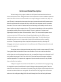
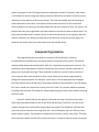
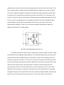
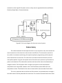
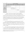
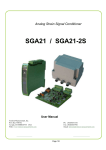
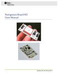
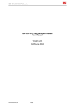
Real Time System Term Project
Pre-Programmed Course Navigator
Marty Peltz
Using the LCPXpresso 1343 microcontroller
ECE 3510
Due: 12/12/2011
Abstract
The Real Time system being produced for my project is a pre-programmed vehicle that
is designed to run a laid out course. The Vehicle itself is driven by two separate motors
controlling the two front wheels. These wheels are powered by a battery and regulated by the
LPCXpresso board. The LPCXpresso board controls a relay for each motor so the motor can be
switched on and off. The vehicle turns by throttling the motors to allow one to move faster
than the other. A constant 6 Volts is supplied to the motors but the relays will allow for pulsing
of the power output. The program is designed to run a pre-programmed course using the
output commands with delays in the programming. This allows each separate program the
ability to run a predesigned course.
Introduction
A Real Time System can be defined as: the study of hardware and software systems that
are subject to a "real-time constraint". The Real Time system I'm implementing requires a
combination of hardware and software working together to complete a physical task. This task
is navigating a course, the software controls the motors through a relay system. Using Output
commands with time delays the motors can be controlled together or separately. The system
design is generally straightforward the program is downloaded and executed from the
LPCXpresso board containing an ARM Cortex processor. The board itself has the required
components to compile and assemble the program in use with the given motors, combined
physical circuit and the power source. The very basic of code as all code for microprocessors
will be in binary format. The binary data to enter the microprocessor is translated from a more
user friendly format: ARM assembly language. Assembly language is more accurate in runtime,
however C is a more general language to use for coding. The programming in code C is used for
simplification and time. As in the real world most programming is done in a high level language
(like C) then for performance purposes it is rewritten in the simpler format Assembly language.
My program requires accuracy and timing to work correctly so editing in Assembly Language is
useful. Editing the program in Assembly allows for the executed programming to be done
accurately and in a timely manner. The primary coding is done on a computer through
LPCXpresso code_red, this is a development tool for the Cortex and ARM devices. The program
will compile and execute ARM Assembly code as well as High level languages. This tool allows
for design, implementation and testing of the program created for the physical system. The
code is downloaded onto the LPCXpresso board via a USB connection, then it can be
implemented and execute the program. The debugging and testing is all done via code_red
software, however trial and error can be done my running the program to execute the physical
application. Each process takes time and need to be refined to create a appropriate model that
fulfills its purpose as an Real Time System.
Reference Model Description
The basic design of my project includes the LPCXpresso board two identical electric
motors and a power source. Along with these initial components a button is added to power on
and off the device. Since the microcontroller has a output voltage of around 1 Volt, relays are
used. The relay is connected to the output from the microcontroller and the 6V power source.
When the microcontroller activates the relay, the 6 Volts from the power source is passed to
the motor. There are a total of 3 wheels two at the front being controlled by the two motors,
then a smaller rear wheel to support the car. This seems the best design so the rear wheel has
the smallest possible effect on the front wheels. The car is made out of a sheet metal
(lightweight material) to reduce friction and other factors. The motors and the power source
are connected to the LPCXpresso board, through downloaded code the ARM processor
initializes and execute a maze traversal using specific given data. The initial data is done
through trial and error so it is known what it takes for the vehicle to perform a specific
movement. The programming is done using the development tool code_red using a PC.
Debugging and testing is completed and it is installed onto the LPCXpresso board for trials and
eventually completion.
This project relies on timing and accuracy to perform its task in maze traversal. This Real
Time system would be classified to have a Hard Deadline. This is due to the fact that if the
vehicle does not correctly navigate the course due to a possible timing error or otherwise it will
vastly effect the outcome. Even if the vehicle is off by a small amount the course navigation
could be impossible. This requires the program to be precise and to account for any variable
that could affect the deadline.
To begin the project the vehicle itself was built first, this allows for direct programming
of the physical system. As well allows for specific designs and programming paths. The point
behind this was mostly for a trial and error method, having the physical system implement and
execute the code showed errors and pitfalls. This will allow me the programmer to alternate
and correct the coding accordingly. With the vehicle being built first and having the known
points to program on the LPCXpresso board the coding was created. The primary code used is
C, this allows for better timing and coding constraints. While Arm Assembly is used for precise
alterations to the code for performance reasons. The code has multiple parts all focusing on
power delivered to the motors. The course contains straits and turns, for the straits both
motors needed to be moving at the same speed over the same amount of time. The motors are
identical but there are irregularities, the code itself has to account for these to be accurate. The
turns have the same issues, however similar to the straits one motor is moving faster than the
other to make the turn. With given data such as the direction of the turn and the angle, the
wheel on the inside of the turns move slower than the outside wheel.
Computer Organization
The programming uses two general commands; GPIO and Delays, these are
incorporated into methods that are used for specific movements of the vehicle. The general
coding includes loops and methods which allow for a repeated command and movement. The
methods are each separated as a different movement of the vehicle, there are methods for
going strait, turning left and right. These methods are called in a certain order to perform a
maze traversal. With these methods in place a new course can be simply programmed by
calling the required methods. For example: a track that is a circle shape with four 90 degree
turns left and four straits 10 feet long. The program would call the method for a turn 90 degree
left, then it would call a method for moving strait for 10 feet. This process would be repeated
by calling more methods. This allows for simple programming of a new course without rewriting
the entire code.
A specific method will use two general commands to power and control the motors.
These two commands include the use of the GPIO and the Delay. The GPIO is the use of the
outputs through the microcontroller using related commands. The LPCXpresso 1343 has four
ports and each port has pins that range from 0-11. Out of these pins some are PIO pins, these
can be used as outputs. Two outputs are needed for this project, one for each motor. The code
turns these two outputs on and off to control the motor. In order to have the motor running for
a certain amount of time a delay is used. For example: if the motor is turned on then a delay of
5 seconds is added then the motor is turned off, this means the motor will run for five seconds
straight. These two commands are used in each of the two methods for each motor. Loops also
take an important part in the program. There are no infinite loop except if the course is to be
continually ran but that loop would not be in the methods. The loops use include if, else
statements that run for a certain length of time then stop. These loops are based on a
timeframe to complete a turn. Loops are only used on turns not straights in the methods this is
because the loops are needed to regulate how many pulses the motor takes. The pulsing of the
motor is used to slow the motor on the inside allowing the vehicle to turn. This pulse has to
eventually be stopped to complete a turn. Depending on how fast the pulse is and how long the
pulsing lasts (using the loop) a certain degree turn can be made. Also this controls how steep
the turn is. Using these two factors through trial and error with the physical vehicle shows how
the motors and weight of the vehicle react allowing for accurate measurements.
Language Choice
The eventually language choice chosen for most of the project was C language, in use
with code_red. C language was chosen over Assembly because it's easier to work with and
saves some time, this allowed me to go back through the code later on to edit it to perform
better with fully functioning code. Code_red was chosen over the MDK ARM development kit
because code_red could be directly connected to the IDE of the Microcontroller. Where MDK
needed a JTAG to compile and upload the code to the flash of the Microcontroller. Using this
allowed for direct upload to test and edit code through a simple process that made things much
easier.
The choice of C language allowed for simple and exact coding using only a few
commands in use with loops. As explained in the Computer Organization portion above the
code consists of using the GPIO commands with timing delays. Using only these two forms of
commands, the code is simple without any errors. This also makes it accurate and precise, so
programming assembly was not really needed. Code_red code is different than the MDK ARM
code in C, I determined this since I used MDK first. Code_red gave quite a few examples of
coding on the LPCX website. The example code GPIO was the most useful and contained most
of the information needed for programming and controlling the outputs. The source code was
partly gathered from the GPIO program, along with the activation of the Ports and pins so they
can be used. The delay is a simple and general command in most cases identical in all forms of
advanced languages as well as using loop architecture.
Input / Output
Output is one of the main factors of my project, the output is required to power the
motors and therefore the prominent part of the entire system. The output through the PIO pins
is essential to my project, they are used to control a relay that in turn controls the motors
themselves. The microcontroller itself has a input pin labeled 5Vin. This allows a 5-6 Volt input
to power the Microcontroller and the output rail. Where the microcontroller requires 1.8 Volts
and the Rail is 3.3 Volts. The output is sent to a relay that uses the voltage from the
Microcontroller's rail Voltage to control a switch. This switch is a separate circuit connected to
the power source for the motor. This is used because the voltage of the Microcontroller is not
sufficient to power the motors.
Figure #1: A mechanical relay with pins 1-5.
The only issue I came across while working with the output pins was the Voltage rail.
The rail is rated at 3.3 Volts however actual voltage would not exceed 2 Volts. This was quite a
problem due to the fact that the relay I was using required a minimum of 3 Volts to work. The 3
volts is used to power a inductor that when powered repels a length of wire to form a switch.
Pin 1 and 2 of Figure #1 would be connected to the Microcontrollers output pin and the other
to the ground. Pin 3 would be connected to the power source while Pin 5 is connected to the
motor Vin. Once the inductor is powered the switch would move allowing the power from Pin 3
to move to Pin 5, completing the circuit. However this doesn't work with a Mechanical Relay,
because Mechanical relays do not work below a 3Volt input to the inductor. Where the
Microcontroller supplies 1-2 Volts. This can be solved using a Solid State Relay where the
voltage can be from mV to a high voltage.
Figure #2: A Solid State Relay with pins 1-4.
The Solid State Relay is used to control a switch for the motor to power on and off, using
an Infrared LED and an adjacent Infrared detector. The Solid State Relay solves the issue of the
microcontrollers output voltage because it will work with 1 Volt or more supplied to the LED.
This Relay in particular activates at 1.1 Volts. Pins 1 and 2 are connected to the Microcontroller
to one of the PIO pins and the other to Ground. Where Pins 3 and 4 are connected to the motor
and the motor's power source. Once the PIO port is activated 1 Volt with power the LED
connecting the switch from the infrared Detector, this will complete the circuit to the motor.
With this circuit the motor is not directly connected to the microcontroller but it is controlled
through the relay by the microcontroller. This circuit is shown in Figure #3 below, there are two
identical circuits in this project one for each motor. To note, the motors are reversed in
connection to the single 6 Volt power source so they move in opposite directions (Left Motor:
Clockwise, Right Motor: Counterclockwise).
Figure #3: Full circuit diagram for the motor control system.
Concurrency
The relation between the two separate motors is very important, they must execute the
same instructions at the same time to be accurate and effective. The two motors need to be
very similar in movement and timing, this requires equal part programming and the physical
motor themselves to be accurate. The two motors are identical and were found to move at
near perfect speeds. Using the same power source for both motors prevents any fluctuation in
power to the batteries. The code needs to activate and control the motors simultaneously to
navigate a course. The LPCXpresso 1343 is a single core system so exact simultaneous
computations are not possible, however such a small timeframe passes before the next
computation is done. This allows for the motors to work within nano-seconds of each other.
This is very important due to the fact that if the vehicle is to proceed strait or through a
turn both motors must be powered at the same time. For a strait movement both motors need
to activate at the same time and be stopped at the same time. Simply to do this both PIO pin
activation commands are executed one after another, then the delay is applied. This delay
keeps both pins from being deactivated until the delay time is passed. Once the delay is passed
both PIO pins are shut off one after the other. There is a extremely short timing delay however
it is so minuscule it has little effect. The vehicle turning on the other hand requires one motor
to move continually, while the other pulses power to slow the wheel down. Both motors are
activated and deactivated the same way as going down a straight away. However there is a
slight larger variance in time between the two motors due to the use of a loop. The loop is a
combination of turning the motor off, a short delay, then turning the motor on. That is what
causes the motor to "pulse". Each time the command to turn on and off the motor causes a
larger gap in the timing. Again, the time is so small it is insignificant. This system is not
completely concurrent, however it relies heavily on accuracy and timing to perform its objective
correctly.
Scheduling
The main design of the coding includes the use of two specific commands using the
GPIO and the delays. To better describe the execution of these commands in the running
system will be shown through a table. This example part of the code will show how the
scheduling works with the code throughout a method. The example will be of the two motors
moving in a straight line. The vertical axis represents time order of operations, while the
horizontal axis represents the transactions in the schedule of the method. Each of the separate
operations take a portion of time to complete.
Table #1: A Table showing the Schedule of the Straight 1 foot Method.
The table above Table #1 shows the schedule of the Method: Straight 1 foot. The
method name is the basic explanation, where these series of commands make the vehicle move
forward 1 foot (on a hard concrete/wood flat surface). Port2 pin 1 is the left motor control
while Port0 pin 7 is the right motor control. The code itself contains other parts including the
source code, however the only important part for scheduling is the direct commands
dependent on time.
The first command is GPIOsetdur, this command takes the port, the pin, then the
input/output setting. So for example; GPIOsetdur(PORT2, 1, 1); means port 2 pin 1 is set to an
output. If the last number was set to 0 it would be an input, however that is never used in this
project. As shown in Table #1 this is the first command to activate, this sets port 2 pin 1 and
port 0 pin 7 to outputs.
The second command is GPIOsetvalue, this command takes the port, the pin then sets
the output to 1. So for example; GPIOsetvalue(PORT2, 1, 1); means port 2 pin 1 is set to high
(1). This sends the rail voltage through the output. So with the complete circuit, Figure #3, it
would activate the relay and in turn activate the motor. The pin will stay high until the same
command is activated and the pin is set to low.
The third and final command is the delay command. As shown in Table #1 this delay is
used in between setting the output pin to high and low. The delay runs the code through a
certain amount of time, the code will not read the next line until the time is finished. The
command: Delay(1520); is based on microseconds, this means the value 1520 is 1.52 seconds.
Therefore the delay command runs the compiler for 1.52 seconds before it can move on. Once
that timeframe it moves onto the GPIOsetvalue that turns the pin to low. From trial and error it
was determined that 1.52 seconds is how long it takes the vehicle to move 1 foot. If the vehicle
needs to move more than 1 foot, the method only needs to be called again for additional feet.
The other method of turning is very similar to the Straight 1 foot method, however one
of the two pins will be pulsing the high and low to slow the motor. The same process as Table
#1 is done except a loop is used in place of Time2 that controls only 1 pin. Within this same
Time2 and Time3 the loop uses a delay to pulse the high/low of the pin. After the loop is
complete and a certain time has passed due to multiple delays. Once these delays are done
both pins are set to low like in Time4.
The important factors of this process require priorities of hard, firm and soft tasks. This
project contains 3 main tasks to prioritize which include; left motor relay control, right motor
relay control, and the program download. The table below shows how I prioritized them as
hard, firm, or soft.
Task
Left Motor Relay
Control
Right Motor Relay
Control
Download
Hard/Firm/Soft System
Hard
Hard
Soft
Table #2: Displays Tasks and if they are Hard, Firm or Soft.
The table above displays the specific tasks used in my programming, and what status
they can take in relation to importance and time. Both the left and right motor relay controls
are defined as a Hard Task due to the fact they are very dependent on a timeframe. If they fail
to succeed then the entire program fails. Since this project requires the vehicle to move in a
precise and accurate manner if the motors are off in turns or movement it will cause
catastrophic errors. The download is the other Task, this is the download of the code to the
flash memory of the microprocessor. This task is important but it has no dependence on time,
which means that it can be edited without causing errors or problems.
Memory Management
The use of code_red IDE made memory management quite easy, where managing the
memory is not necessary to an extent. The code_red IDE download directly uploads the code to
the flash memory of the microprocessor. This allows for direct debugging to the board for
testing and editing. Memory management doesn't cause an issue with this process because the
flash memory is rewritten when code_red runs the debug. Memory management does come
into play for my program however due to the fact of using methods . The main program calls
the specific methods to perform the task done in the method.
The methods which hold the code for each specific task or movement can be used with
memory management to simply upload a new method call program. This new program can call
specific preloaded methods allowing the same methods to run multiple different types of
courses. This is one good possibility for managing the memory allocation, however it is not
necessarily needed because new code can be directly downloaded through code_red. It is a
promising idea for an addition to the project if it was to run multiple courses without updating
or altering the code between each course. This is not a necessity of the project however it is
preprogrammed to run a specific course. Therefore memory management doesn't play a large
part other than what the code_red IDE does to format the flash memory on the project board.
Shared Memory
This project contains shared memory in the form of methods, these methods are not
accessed simultaneously but by a single program that calls each method in order to complete a
maze. Methods are not required to have the maze traversal vehicle to work but allows for a
simple repetition in the code. This repetition allows the program to reuse the code through a
method to create different maze traversals. Methods are really the only use of shared memory
similar to memory management, these methods contain the basic and principle standing of the
code to be used. The methods created for this project includes running a straight path and
turning 90 degrees. Other methods can be added such as different degree turns over longer or
shorter distances. With multiple methods just about any course can be navigated calling the
different methods. Otherwise there is little use in shared memory, the program is good to keep
simple and precise for accuracy concerns.
Operating Systems
The system used is the LPCXpresso 1343 containing a ARM Cortex-M3 processors, it's a
single core processor with 32KB of flash memory and 8KB of SRAM. The IDE used in conjunction
is LPCXpresso code_red, which directly applies code to the flash memory of the microcontroller.
The debugging process of the code_red runs, tests, and downloads the code. The code operates
initially when the microcontroller is powered on. Using a power source with a switch the
program can be initialized and executed. This process isn't overly complicated unlike the use of
the MDK-ARM IDE where it requires the use of an JTAG.
Using C code as the basis for executing programming requires startup code to activate
the microprocessor. The startup begins with declaring the default handlers for the program. It
then moves into defining and declaring the specific IRQ handlers for the program. The entry
point for the code is then defined so the microprocessor understands where to search for given
code. The startup then activates the physical pins and ports for input/output uses. Then the
startup defines constructs created by the linker, this indicates where the "data" and "bss"
segments reside in memory. Directly following the "data" segment is the "text" segment.
With the handlers, pins, ports activated, and the segments in specific areas in the
memory; the startup defines what gets called to the microprocessor. This part of the startup
activates the programs code for running. Also the startup enters the program into a infinite
loop for debugging purposes. The startup is generally the same for all programs with some
irregularities. My program requires no special setups so the general startup is executed then
the application begins. This setup portion is called cr-startup_lpc1343.c it is visible in the given
source code after the bibliography.
The next portion is initializing the use of the GPIO for my program. This is done by gpio.c
in the project program. This code sets the PIO pins to be used with an interrupt handler so the
pins can be set to high or low. The pins must first be set as generic integers and are all set to
low values. The pins that are to be used are to be set as interrupt sources so the
microcontroller recognizes them. Then the command for GPIOsetdur, and GPIOsetvalue are
initialized using if else statements. This has to be used so the microcontroller can understand
the commands through assembly language with bit positions of each element. With all the
initial setup completed the code written for the maze traversal can be ran.
Results
The overall project works quite well, the code runs and executes correctly and with the
trial and error and strong link between the code and physical outcome is quite accurate. The
issues that appeared were mechanical related mostly. The weight of the vehicle with the
motors power source causes some irregularities. This project relies on accuracy to successfully
accomplish a maze traversal. Being a physical moving object, many applications of physics come
into play and affect the project in many ways.
The code itself for the project is simple and very accurate, with the use of trial and error
the accuracy of the maze traversal becomes very precise. Using methods with the code and
having it altered to work with the surface and other physical restrictions allow it to work quite
well in that environment. The vehicle is designed to work on a smooth flat surface and perform
turns and movements on that terrain. After testing and alterations to the code the vehicle
performs flawlessly. The code itself is easy to alter, the timing between delays can be changed
to better suit the lag or run over a desired distance. Also the pulse of a motor can be altered by
changing the delay within the loop. This resulted in accurate movements after trial and error
evaluation.
The vehicle was designed to run a single course that is an oval shape that runs 10 feet
long by 5 feet wide. Each turn is 2 feet long with a angle of 90 degrees. The vehicle is made to
run the course counter clockwise. For each turn the right motor is on the outside while the left
is on the inside of the turn. The straight lanes were quite easy to accomplish with timing the
delay just right. The turns were more challenging due to the fact of the motors torque and the
weight of the vehicle. I found to actually stop one wheel from turning caused the vehicle to
stop due to the amount of torque on the right motor (on the outside of the turn). This
prevented the vehicle from taking to tight of turns, however if the inside motor was to pulse, it
would move slower and allows the outside wheel to overtake it. This created a sluggish turn
that proved to be effective to a point. The vehicle was only able to make a loose turn of 90
degrees after about a foot and a half. Since the turn of the oval maze is 2 feet this was not a
problem. With the width of the actual track being 1.5 feet and the car being 8 inches wide, the
vehicle was able to stay within the track the entire way around the oval. Trial and error was
needed to adjust the turns and straits so this was possible. However since the code is written in
methods they were permanently altered to work in the specific conditions. Repeated attempts
at the maze traversal accomplished very similar movements. The project shows an overall
success with minor discrepancies due to small mechanical or symmetrical errors.
Conclusions
Overall the project worked out quite well, the use of methods help to bring a symmetry
to the code and allow for future additions to be made simply by calling the methods. This
allows for future applications and editing to be simple and strait forward. The only real issues
that presented themselves were mechanical related. The vehicle itself is constructed out of
sheet metal with the motors directly attached. With this program requiring exact and accurate
specifications made it hard building from scratch. Issues came to light when attaching the
motors to the chassis. It was hard to align them correctly and make them symmetric. Also the
rear wheel was not functioning as expected being able to rotate, it was better suited to be
stationary. It's due to the fact of the weight on the rear wheel and if it gets stuck in a sideways
position it affects the movement of the car. The motors used performed well but probably
could of been more powerful. The motors are under a lot of strain due to the weight. This
brought problems to turning especially because if only one wheel was powered it would not
even move due to the immense strain on the one motor.
The trial and error method worked quite well, it allowed linking the code to physical
issues that may occur. The only other way to cope with such issues would be multiple
calculations related to physics to determine outside problems. Even those calculations couldn't
completely fix the errors. Overall the trial and error allowed for testing of the vehicles
limitations and possibilities. The trials may have been limited to a flat hard surface, but
alterations can be made. If I wanted to run it on a carpeted surface, new methods could be
made and trials be conducted to find how that affects the vehicles movement.
Overall the project was a good success and future alterations are very possible and
would be easy to manage. With some problems mainly mechanical and physical related it did
have some errors. Being made from scratch it's not too surprising however accuracy can be
hard to obtain without precise machinery to cut holes and drill screws. Unfortunately the
project couldn't be presented fully during is due time. However that was not due to failure of
the project, but a part was missing and also the vehicle didn't have a good test location. The
room was carpeted and the vehicle was made to run on flat smooth surfaces. With further trial
and error a successful maze traversal was completed, repeatedly. This confirms the project is a
success and has completed its task in being a Pre-Programmed Course Navigator
Bibliography
(MLA Format)
Embedded Artists. "GPIO Example Code." Http://ics.nxp.com/lpcxpresso/~LPC1343/. NXP.
Web. 5 Nov. 2011.
<http://ics.nxp.com/support/lpcxpresso/zip/examples.lpc13xx.zip>.
Embedded Artists. "Lpcxpresso Lpc1343 Schematic." Http://ics.nxp.com/lpcxpresso/. NXP, 4
Dec. 2009. Web. 22 Oct. 2011.
<http://ics.nxp.com/support/documents/microcontrollers/pdf/lpcxpresso.lpc1343.schemat
ic.pdf>.
NXP. "Getting Started with NXP LPCXpresso." Http://ics.nxp.com/lpcxpresso/. NXP, 14 June
2011. Web. 12 Sept. 2011.
<http://www.nxp.com/documents/other/LPCXpresso_Getting_Started_Guide.pdf>.
NXP. "LPC1311/13/42/43 User Manual." Http://ics.nxp.com/lpcxpresso/. NXP, 14 June 2011.
Web. 12 Sept. 2011.
<http://ics.nxp.com/support/documents/microcontrollers/pdf/user.manual.lpc13xx.pdf>.
"Photocouplers and Photorelays." Http://www.digikey.com. Toshiba, 2011. Web. 18 Nov. 2011.
<http://www.semicon.toshiba.co.jp/docs/catalog/en/BCE0034_catalog.pdf>.