1
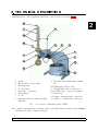
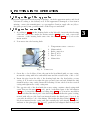
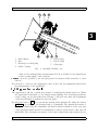
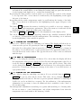
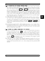
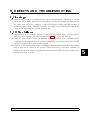
INGOS s.r.o.
ROTARY VACUUM EVAPORATOR
RVO 200 A
User manual
PRAHA
Oct 12 2004
Producer
:
INGOS
Supplier and service
:
INGOS s.r.o.
K Nouzovu 2090
14316 PRAHA 4
(c) INGOS 2004
Tel: +420 2 96781683
+420 2 96781692
Fax: +420 2 44403051
e-mail:[email protected]
INTRODUCTION
TECHNICAL DESCRIPTION
PUTTING INTO OPERATION
MAINTENANCE
DEFECTS AND TROUBLESHOOTING
SAFETY AND OPERATION CONDITIONS
ACCESSORIES AND SPARE PARTS
CONCLUSION
TABLE OF CONTENTS
1
2
3
4
5
6
7
8
9
1
1. INTRODUCTION
1.1 Apparatus use and specications
Rotary vacuum evaporator RVO 200 A is designed for low-pressure evaporation at the
pre-set value of the heating bath temperature and at the pre-defined constant mixing
process of the solution to be vaporised. The vapours exhausted condense in a vertical
cooler and are collected into a flask. Thus it is ensured that the vaporised solution
will not be damaged and spoiled. The apparatus is fitted with an underpressure
measuring system and optionally with an additional device designed for the control
of the vacuum pump operation. This device is especially important for the vaporising
of heavily volatising substances.
1.2 Technical characteristics
Range of revolutions . . . . . . . . . . . . . . . . . . . . . . 10 up to 200 rpm
Bath temperature . . . . . . . . . . . . . . . . . . . . . . . . max. 100o C for water filling
max. 180o C for oil filling
Measurement and regulation . . . . . . . . . . . . . . two platinum thermometers, the first one
in the heating system of the bath,
the other one in the bath filling
Regulation accuracy . . . . . . . . . . . . . . . . . . . . . . 1o C up to 100o C
3oC up to 180oC
Pressure difference . . . . . . . . . . . . . . . . . . . . . . . . 50 hPa (can be modified according
to user’s requirements)
Power supply . . . . . . . . . . . . . . . . . . . . . . . . . . . . . 230V, 10%, 50Hz
Category of overvoltage in the installation .II.
Power input . . . . . . . . . . . . . . . . . . . . . . . . . . . . . . max.1350 VA
Weight without glass . . . . . . . . . . . . . . . . . . . . . 16 kg
Dimensions (w x h x d) . . . . . . . . . . . . . . . . . . . 520 x 530 x 380 mm (including glass)
INGOS s.r.o.
Page 4
2. TECHNICAL DESCRIPTION
Individual parts of the apparatus and their location can be seen from fig. 1.
2
14
7
4
15
10
2
5
12
1
6
9
13
11
8
3
1.
2.
3.
4.
5.
6.
7.
8.
Stand
Head with a rotary casing
Heating bath
Cooler holder
Suck pipe - reduction
Ball adapter
Cooler
Ball-and-socket ground joint flask
1000 ml
9. Round bottom flask 1000 or 2000
ml
10. Filling pipe with a valve
11. Temperature sensor connection
12. Flexible clip : a) metal, b) plastic
13. Fixed clip
14. Outlet - underpressure connection
15. Outlet - cooling water connection
Fig. 1. Location of individual parts of RVO
The complete apparatus also includes : inlet cord, flask with a round bottom (2000ml),
arresting rod, gufero sealing 35/20/10.
INGOS s.r.o.
Page 5
3. PUTTING INTO OPERATION
3.1 Unpacking of the apparatus
Unpack the apparatus from the transport package, check the apparatus surface and check
all items according to the delivery note. If the apparatus is damaged or if an item is
missing, contact the manufacturer or your supplier. Caution: apply silicone jelly to
the glass ground joints, possibly wind a Teflon tape around them.
3.2 Apparatus assembly
1. According to fig. 1 put the heating bath on the lift table, insert the inlet heating
cable into the socket under the mains switch (fig. 2 pos.3). and connect the
connector of the heating bath sensor into the socket (fig. 2 pos.1) above the
mains switch.
2. Pour water into the heating bath.
1
2
3
4
1.
2.
3.
4.
5.
6.
Temperature sensor connector
Mains switch
Bath connection
Fuse T 0.5A
Fuse T 6.3A
Mains inlet
5
6
Fig. 2. Connectors
3. Screw the cooler holder rod into the nut in the head fitted with a rotary casing,
mount the casing with holes and milled nuts and the actual holder of the cooler.
4. Insert the pipe from the side of the heating bath into the head with a rotary
casing, do it in such a way that the pipe ground joint can latch behind the ring
situated in the rotary casing. Insert the arresting rod into the hole in the rotation
casing and tighten the rotary casing nut.
5. The opposite side of the head with the rotary casing contains a fixed casing with
a nut. Unscrew the nut (fig. 3 pos.2), put it on the fitted part of the ball adapter
(fig. 3 pos.1), insert the bead-type securing ring (fig. 3 pos.3) in such a way that it
can latch behind the fitted part of the ball adapter. Check that the gufero sealing,
treated with silicone jelly, has been inserted inside the fitted part (?? pos.4), its
open side should face out of the fitting. Check that the flat sealing (fig. 3 pos.5)
has been inserted in the casing and put carefully the ball adapter with gufero
and nut on the glass pipe (fig. 3 pos.6), push the ball adapter until it stops and
INGOS s.r.o.
Page 6
3
RVO 200A
Section 3: PUTTING INTO OPERATION
1
2
3
3
4
1.
2.
3.
4.
Ball adapter
Nut
Bead-type securing ring
Gufero sealing
5
6
7
5. Flat sealing
6. Glass pipe
7. Fixed casing
Fig. 3. Assembly drawing
6.
7.
8.
9.
10.
11.
12.
13.
tighten the nut properly (fig. 3 pos.2). The half-circle ground joint of the ball
adapter faces down.
Apply silicone jelly finely to all ground joints on other glass parts.
Put the cooler into the ground joint in the upper part of the ball adapter and
at the same time into the cooler holder. The upper outlet of the cooler serves
for the connection of the underpressure source. Other outlets serve for cooling
water. The outlet situated in the lower part of the stand serves for the measurement of underpressure. Connect the outlet of the cooler for the measurement
of underpressure to the outlet for the measurement of underpressure and to the
underpressure source with the help of a ”T” fitting.
Attach the ball-and-socket ground joint to the round adapter ground joint with
the help of a fixed clip, tighten properly.
Put the round bottom flask on the pipe and secure it with a flexible clip.
Insert the releasing pipe with a valve (the valve is closed) into the ball adapter.
Connect the mains cord. (fig. 2 pos.6)
Pour approximately 1 l of liquid into the heating bath, lift the heating bath
with the help of the lift to its working position, adjust the stop of the lift and
fill in the liquid in the heating bath in such a way that the round-bottom flask
can be sufficiently immersed in the liquid. The maximum amount of liquid is
approximately 20 mm below the edge of the heating bath.
If the apparatus is fitted with additional equipment for the vacuum pump control,
connect the interconnection cable of this equipment into the socket above the
INGOS s.r.o.
Page 7
RVO 200A
Section 3: PUTTING INTO OPERATION
1
2
3
3
4
1.
2.
3.
4.
Ball adapter
Nut
Bead-type securing ring
Gufero sealing
5
6
7
5. Flat sealing
6. Fixed casing
7. Glass pipe
Fig. 4. Assembly drawing - řez
outlet for the underpressure measurement. For more details see the instructions
for the vacuum pump control system.
Caution : It is not possible to use the glass part if it features visible scratches or other
defects !
It is allowed to connect to the equipment control socket only the equipment delivered by
the manufacturer of the apparatus!
3.3 Apparatus control
The apparatus is put into operation by means of switching the mains switch on. When
the apparatus is switched on, the display starts lighting. The head fitted with the
rotary casing can be tilted after the releasing of the star nut. After the adjustment
of the head inclination tighten the star nut again.
By using the button UP you can lift the heating bath upwards. By using the button
DOWN you can make the heating bath go downwards. The upward movement of
the bath is limited by the adjustable end switch which is situated on the rear part
of the apparatus stand and whose adjustment is carried out by means of the exposed
milled nut. The downward movement of the bath is limited through a firmly pre-set
INGOS s.r.o.
Page 8
RVO 200A
Section 3: PUTTING INTO OPERATION
end switch. Be careful! While you are lifting the heating bath pay particular attention
for the heating bath liquid not to overflow the heating bath.
By pressing the button with a rotation symbol you can start the rotation of the sample
to be vaporised. The correct function is indicated by the highlighting in the upper
left part of the button.
By pressing the key with a temperature symbol you will initiate the heating of the bath.
The correct function is indicated by the highlighting in the upper left part of the
button.
The button 1 2 represents the memory in which it is possible to store two settings of
the revolution and temperature parameters. The active memory is indicated by the
highlighting in the upper left (right) part of the button.
The buttons LESS and MORE serve for the adjustment of the display value.
The arrow button serves for the switching between the variables measured. RPMrevolutions, o C-temperature and hPa-underpressure. The switching over is indicated
by the highlighting of the variable in question.
3.3.1 Adjustment of revolutions
Switch over to RPM by using the switching-over button. The display will show the revolutions value pre-set. By pressing the buttons LESS or MORE you can change
this value. If you keep these buttons pressed for a longer time, the speed of change in
the value to be set will increase on a progressive basis. The apparatus enables you to
set both directions of the rotation. The opposite direction of the rotation is indicated
with the sign - .
3.3.2 Setting of temperatures
Switch to o C by using the switching-over button. For a short time the display will show
the temperature value pre-set, which is followed by the real temperature value. If you
touch the buttons LESS or MORE the pre-set value will be shown. This value
can be changed by pressing the above mentioned buttons. If you keep these buttons
pressed for a longer time, the speed of change in the value to be set will increase on
a progressive basis.
3.3.3 Adjustment of underpressure
Switch to hPa by using the switching-over button. If you touch the buttons LESS or
MORE the pre-set value will be shown. This value can be changed by pressing
the above mentioned buttons. The factory pre-set pressure difference of switching is
50 hPa (it can be modified at a request). For the utilisation of the underpressure
adjustment it is necessary to have an additional device available for the control of
the vacuum pump.
The underpresure adjustment is switching-on together with switching-on of heating bath.
In case we want to control underpresure only adjust temperature lower than the
temperature air is and swith-on the heatying of bath.
INGOS s.r.o.
Page 9
3
RVO 200A
Section 3: PUTTING INTO OPERATION
3.3.4 Adjustment of operating time (Timer)
Switch to Time by using the switching-over button. The pre-set value of the operation
time. If the time in value 00:00 is pre-set , the operating time is not limited. Pre-setting
carry out by using the buttons LESS and MORE . When the rotation is switched
ON , the time is measured. The measuring is indikated by the flashing display, showing
indikation TIME. When the full pre-set time is, the heating bath operation and the
rotation is switch OFF. If the apparatus is equiped by the additional device available
for the control of the vacuum pump , the vacuum pump is switch OFF together with
the heating bath operation . The spindle keeps the electrical block-out and the display
shaws permanent final value of the time.
Note: The setting of revolutions, temperature underpressure and time can be carried out
also if the rotation and heating bath operation are ON. Be careful while adjusting
revolutions if the apparatus is in operation! The adjustment should be carried out
only by means of repeated short pressings of the buttons LESS and MORE . If you
keep the above mentioned buttons pressed, you will achieve maximum revolutions in
a short time!
After switching the apparatus ON or while switching the memory over you must observe
the principle that the rotation is always OFF, which holds for the operation of the
heating bath as well. We recommend you to check the pre-set rate of revolutions still
before you switch the rotation ON.
3.3.5 Storing the values pre-set into the memory
If the window is highlighted above the number 1, you are storing the data into the memory
1, namely by pressing the button 1 2 for a time of at least 5s (the window above
the number 1 shall turn on again). Thus you will store the current setting of rotation,
temperature pressure and operating time. If you do not want the operating time to
limit , you will store into the memory the setting of the time 00:00. By every pressing
the button 1 2 you will switch over to the second memory. The setting is carried
out by same way as for the first memory.
The values pre-set can be changed even during the apparatus operation. If you do not
store them again, the apparatus will remember the last adjustments stored and the
apparatus will automatically switch over to these settings after being switched OFF
and ON.
INGOS s.r.o.
Page 10
3
4. MAINTENANCE
4.1 Apparatus maintenance
Do not leave the apparatus surface contaminated from corrosive substances. It could
damage the coating of the apparatus. Clean the apparatus surface with a clean soft
cloth. The cloth may be moistened but not wet. It is also possible to use ordinary
washing means for cleaning purposes. It is forbidden to clean the heating bath with
the means which could spoil its Teflon surface. Apply a light layer of silicone jelly to
the gufero sealing approximately after 80 operation hours (more often if necessary).
Caution: Disconnect the apparatus from the network while cleaning it with a wet
cloth!
4.2 Sealing replacement
Disassemble the cooler, remove the releasing pipe with the valve, remove the ball-andsocket ground joint flask, release the nut of the ball adapter and carefully remove
the actual adapter. Release the gufero sealing, clean the ball adapter, slightly apply
silicone jelly onto the new sealing and mount it into the ball adapter. The sealing
cavity faces out of the ball adapter. If necessary, replace also the flat sealing between
the ball adapter and the head fitted with a rotary casing. Perform the assembly
according to the point 3.2
INGOS s.r.o.
Page 11
4
5. DEFECTS AND TROUBLESHOOTING
5.1 Leakage
The main cause of leakage is usually an incorrect sealing assembly. At first you should
check that all ground joints have been installed correctly. If it is the case, disassemble
the glass and verify the condition of the ball adapter sealing and flat sealing, if
necessary replace them. Carefully assemble according to the instructions, switch the
rotation ON and start the vacuum pressure up.
5.2 Other failures
The apparatus does not respond when you switch it ON. Check fuses, possibly replace
with new ones featuring the same parameters (fig. 2, T 0.5A and T6.3A).
The window of the rotation button is flashing. Check that there is not anything which
could impede the sample from its rotation (manually), switch the mains switch OFF
and ON and press the rotation button again.
The window of the temperature button is flashing. This indicates that the temperature
sensors have been connected incorrectly. Check the sensor connection, quantity of
liquid in the heating bath and switch the mains switch OFF and ON and press the
temperature button again.
INGOS s.r.o.
Page 12
5
6. SAFETY AND OPERATION CONDITIONS
6.1 Operation safety
Ensuring of rotation of the sample to be vaporised:
Current protection of the driving motor. If the resistance against rotation
has increased above the pre-specified limit, the
driving motor voltage will be disconnected.
(This situation will be signalled by the flashing
of the rotation LED)
Protection of the heating bath lift:
Friction coupling between the driving motor
and lifting equipment. In the case of an increase in resistance during the lifting of the bath
above the specified limit the friction coupling
could slip.
Protection of bath heating:
Electronically by means of a thermal protection against overheating. There will not be
any heating if the incorporated sensor of the
heating bath has been connected or if the difference of temperatures between sensors rises
above the limit pre-specified by the manufacturer. (This situation will be signalled by
the flashing of the LED for heating)
6.2 Operation conditions
The apparatus is designed for the work under ordinary laboratory conditions at temperatures of 10 to 30o C and air humidity up to 80% . The power supply is 230 V, 6 A,
50 Hz. The inlet cord should be connected into a socket circuit featuring protection
from 10 or 16 A. The inlet cord cannot be in contact with the heating bath. The
socket designed for the connection of the heating bath is designed exclusively for this
bath. Oil used in the bath must be designed for a temperature of at least 180o C. The
bath volume shall not exceed 2 l.
It is forbidden to handle any bath which has been heated to a temperature exceeding 40o C
in any other way than by using the apparatus lift. If you want to fill the liquid into the
heating bath, always switch the vaporised sample rotation OFF. For temperatures
up to 100o C use water as the filling of the heating bath (with regard to its higher
thermal capacity).
Caution! If you are replacing the round-bottom flask after the vaporised solution has
become thicker, pay particular attention and if it is not possible to remove the flask
easily from the cone, carry out any other handling only after the cooling of the bath.
Caution! If you use oil as the filling of the heating bath, the heating bath must be properly
dried before its being filled.
INGOS s.r.o.
Page 13
6
RVO 200A
Section 6: SAFETY AND OPERATION CONDITIONS
If you are working with oil heated above 100o C, you must ensure that no water
can enter into the oil. If you are replacing the round-bottom flask, pay particular
attention that no water drops shall enter into the oil. While working, use personal
protection equipment (goggles, gloves, coat and shoes).
Caution!
6
INGOS s.r.o.
Page 14
7. ACCESSORIES AND SPARE PARTS
7.1 basic accessories
inlet cord
glass series
arresting rod
gufero sealing 35/20/10
flat sealing
clips
cooler holder
7.2 Other accessories
It is possible to order other accessories to the apparatus.
1. Vacuum pump control system ( In your orders always specify the vacuum pump
type, type identification, power input and whether the vacuum pump is fitted
with the non-return valve on the suction side.)
Vacuum pump control system with the vacuum pump ( In your order always
specify limiting pressure and pumping speed.)
2. ”T” fitting
3. Glas part (fig. 1 item 9) other sizes
flasks 50, 100, 250, 500 ml
spider with 6 sleevs for test tubes (grinding-in) 20 ml
test tubes with grinding-in 20 ml
spider with 5 sleevs for flask 100 ml
spider with 5 sleevs for flask 250 ml
7.3 Spare parts
It is possible to order following spare parts from the manufacturer or seller of the apparatus.
Flat sealing
Gufero sealing
Glass set or individual parts of glass according to the description.
Firm clip
Flexible clip - metal
Flexible clip - plastic
Cooler holder
Fuses: T 6.3 A , T 0.5 A
Inlet cord
Cooler outlets
INGOS s.r.o.
Page 15
7
8. CONCLUSION
8.1 Carrying out of repairs
All warranty and after-warranty repairs shall be carried out by the manufacturer or by
the organisation authorised by them. If the delivery note does not state otherwise,
contact the manufacture for any repair requirements.
8.2 Warranty
The product is covered by the manufacturer’s warranty lasting for one year from the day
of the handing over to the customer of the product. The apparatus can only be used
in the way specified in these instructions. The apparatus cannot be used in any other
way than as provided for in these instructions, otherwise the operation safety could
be interfered. If the conditions of these instructions are not met, the manufacturer
will not be liable for damages which could arise.
8
INGOS s.r.o.
Page 16
9. TABLE OF CONTENTS
1. INTRODUCTION . . . . . . . . . . . . . . . . . . . . . . . . . . . . . . . . . . . . . . . . . . . . . . . . . . . . . . . . . . . . . 4
1.1 Apparatus use and specifications . . . . . . . . . . . . . . . . . . . . . . . . . . . . . . . . . . . . . . . . . . 4
1.2 Technical characteristics . . . . . . . . . . . . . . . . . . . . . . . . . . . . . . . . . . . . . . . . . . . . . . . . . . 4
2. TECHNICAL DESCRIPTION . . . . . . . . . . . . . . . . . . . . . . . . . . . . . . . . . . . . . . . . . . . . . . . . . 5
3. PUTTING INTO OPERATION . . . . . . . . . . . . . . . . . . . . . . . . . . . . . . . . . . . . . . . . . . . . . . . . 6
3.1 Unpacking of the apparatus . . . . . . . . . . . . . . . . . . . . . . . . . . . . . . . . . . . . . . . . . . . . . . . 6
3.2 Apparatus assembly . . . . . . . . . . . . . . . . . . . . . . . . . . . . . . . . . . . . . . . . . . . . . . . . . . . . . . 6
3.3 Apparatus control . . . . . . . . . . . . . . . . . . . . . . . . . . . . . . . . . . . . . . . . . . . . . . . . . . . . . . . . 8
3.3.1 Adjustment of revolutions . . . . . . . . . . . . . . . . . . . . . . . . . . . . . . . . . . . . . . . . . . 9
3.3.2 Setting of temperatures . . . . . . . . . . . . . . . . . . . . . . . . . . . . . . . . . . . . . . . . . . . . 9
3.3.3 Adjustment of underpressure . . . . . . . . . . . . . . . . . . . . . . . . . . . . . . . . . . . . . . . 9
3.3.4 Adjustment of operating time (Timer) . . . . . . . . . . . . . . . . . . . . . . . . . . . . . 10
3.3.5 Storing the values pre-set into the memory . . . . . . . . . . . . . . . . . . . . . . . . 10
4. MAINTENANCE . . . . . . . . . . . . . . . . . . . . . . . . . . . . . . . . . . . . . . . . . . . . . . . . . . . . . . . . . . . . . 11
4.1 Apparatus maintenance . . . . . . . . . . . . . . . . . . . . . . . . . . . . . . . . . . . . . . . . . . . . . . . . . 11
4.2 Sealing replacement . . . . . . . . . . . . . . . . . . . . . . . . . . . . . . . . . . . . . . . . . . . . . . . . . . . . . 11
5. DEFECTS AND TROUBLESHOOTING . . . . . . . . . . . . . . . . . . . . . . . . . . . . . . . . . . . . . . 12
5.1 Leakage . . . . . . . . . . . . . . . . . . . . . . . . . . . . . . . . . . . . . . . . . . . . . . . . . . . . . . . . . . . . . . . . . 12
5.2 Other failures . . . . . . . . . . . . . . . . . . . . . . . . . . . . . . . . . . . . . . . . . . . . . . . . . . . . . . . . . . . 12
6. SAFETY AND OPERATION CONDITIONS . . . . . . . . . . . . . . . . . . . . . . . . . . . . . . . . . 13
6.1 Operation safety . . . . . . . . . . . . . . . . . . . . . . . . . . . . . . . . . . . . . . . . . . . . . . . . . . . . . . . . 13
6.2 Operation conditions . . . . . . . . . . . . . . . . . . . . . . . . . . . . . . . . . . . . . . . . . . . . . . . . . . . . 13
7. ACCESSORIES AND SPARE PARTS . . . . . . . . . . . . . . . . . . . . . . . . . . . . . . . . . . . . . . . . 15
7.1 basic accessories . . . . . . . . . . . . . . . . . . . . . . . . . . . . . . . . . . . . . . . . . . . . . . . . . . . . . . . . . 15
7.2 Other accessories . . . . . . . . . . . . . . . . . . . . . . . . . . . . . . . . . . . . . . . . . . . . . . . . . . . . . . . . 15
7.3 Spare parts . . . . . . . . . . . . . . . . . . . . . . . . . . . . . . . . . . . . . . . . . . . . . . . . . . . . . . . . . . . . . . 15
8. CONCLUSION . . . . . . . . . . . . . . . . . . . . . . . . . . . . . . . . . . . . . . . . . . . . . . . . . . . . . . . . . . . . . . . 16
8.1 Carrying out of repairs . . . . . . . . . . . . . . . . . . . . . . . . . . . . . . . . . . . . . . . . . . . . . . . . . . 16
8.2 Warranty . . . . . . . . . . . . . . . . . . . . . . . . . . . . . . . . . . . . . . . . . . . . . . . . . . . . . . . . . . . . . . . . 16
9. TABLE OF CONTENTS . . . . . . . . . . . . . . . . . . . . . . . . . . . . . . . . . . . . . . . . . . . . . . . . . . . . . 17
9.1 List of picturtes and tables . . . . . . . . . . . . . . . . . . . . . . . . . . . . . . . . . . . . . . . . . . . . . . 17
9.1 List of picturtes and tables
Fig.
Fig.
Fig.
Fig.
1.
2.
3.
4.
Location of individual parts of RVO . . . . . . . . . . . . . . . . . . . . . . . . . . . . . . . . . . . . . . . .
Connectors . . . . . . . . . . . . . . . . . . . . . . . . . . . . . . . . . . . . . . . . . . . . . . . . . . . . . . . . . . . . . . . . .
Assembly drawing . . . . . . . . . . . . . . . . . . . . . . . . . . . . . . . . . . . . . . . . . . . . . . . . . . . . . . . . . .
Assembly drawing - řez . . . . . . . . . . . . . . . . . . . . . . . . . . . . . . . . . . . . . . . . . . . . . . . . . . . . .
INGOS s.r.o.
Page 17
5
6
7
8
9