1
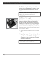
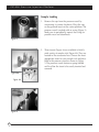
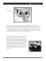
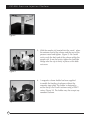
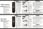
Model PIP-500
Pressure Injection Platform
User’s Guide
New Objective, Inc.
2 Constitution Way
Woburn, MA 01801-1023 USA
888 220 2998 Orders
781 933 9560 Phone
781 933 9564 Fax
www.newobjective.com
© 2004 New Objective, Inc.
All rights reserved.
Rev 1.0
NEW
OBJECTIVE
The New Objective PIP-500 pressure system for “bomb” injection sample loading
is specifically designed for use with the magnetic interlock plate design of the new
PicoView™ 150, 400 and 500 Series. With no tools — or even screws — required the PIP500 is simple to use. The system includes a universal magnetic holder for use with sources
other than PicoView.
Tools and supplies needed for installation:
Crescent wrench
Length of stainless steel, copper or Teflon tubing
Supply of high-purity helium
Set of Allen wrenches (supplied)
Contents of PIP-500 package
(1)
(1)
(1)
(1)
(1)
PIP-500 Pressure Injection System
Plexi-glass protective shield
Set of Allen wrenches
Accessories Box
- (3) Insert Sleevs
- (5) Grauated micropipettes
- (1) magnetic union holder
- (10) SealTight™ Sleevs
- (5) SealTight Ferrules
- (1) Snubber Fitting
- (2) Short PEEKNuts
- (3) Low-head Screws (for plexi-glass shield)
- (1) Valve component
PIP-500 User’s Guide
1
PIP-500 Pressure Injection Platform
The PIP-500 is shipped with the protective shield
separate. It is recommended that the protective shield
be attached before operating the pressure injection
system.
WARNING: Always wear ANSI-approved protective
goggles while operating any high-pressure
instrumentation.
Installation of Gas Supply
Figure 1
Before helium gas is supplied to the pressure injection
platform the protective shield should be installed to
the base of the unit using the three low-head screws
supplied in the accessories box. For your convenience
a set of Allen wrenches is supplied with the unit. The
protective shield has been designed to protect the user
during the injection process and once installed should
not be removed. (Figure 1)
1. Find the three low-head screws in the accessories
box.
2. Locate the three tapped holes in the base of the
PIP-500. Place the bottom of the plexi-glass shield
against the base of the PIP-500 unit. Align the holes
in the shield to those in the base and secure with
the three low-head screws.
WARNING: Do not attempt to operate unit without the
protective shield securely locked in place.
2
NEW
OBJECTIVE
The helium is supplied to the pressure injector though
a swagelock three way valve attached to the pressure
vessel. A swagelok fitting designed to accommodate
1/8” tubing is supplied in the accessories box, as seen
in Figure 2. The valve is shipped without the proper
fittings attached. Attach the fitting to one side of the
valve. For convenience choose the side which is closest
to the location of the helium source. Using Teflon tape
is recommended to ensure a tighter seal.
3. On the other side of the valve attach the Snubber
fitting. The snubber fitting contains a porous
stainless steel frit which acts to protect liquid
samples from pressure shocks and surges as helium
is released from the pressure vessel. (Figure 2)
4. Lastly attach the supply of helium to the 1/16”
fitting. Teflon tape may again be applied for a
tighter seal. Follow the instructions provided to
properly tighten the swagelok fittings.
Figure 2
Operation of the 3-Way Valve
1. Pressurize the vessel by turning thethe ointed side
of the valve knob towards the helium source.
2. Placing the valve in the neutral position will stop
the flow of gas either in or out of the vessel.
3. Turn the poited side of the valve knob towards the
snubber firring to release pressure from the vessel.
3
PIP-500 Pressure Injection Platform
Sample Loading
1. Remove the cap from the pressure vessel by
unscrewing it counter clockwise. Place the cap
on the grooved insert on the center platform. The
pressure vessel is sealed with an o-ring (Figure 3).
Make sure to periodically inspect the o-ring for
possible wear and cleanliness.
Figure 3
2. Three inserts (Figure 4a) are available to hold a
wide variety of sample vials (Figure 4b). They are
located in the accessories box. Choose the most
appropriate insert for your sample vial and place
both in the pressure vessel as shown in Figure
5. The pressure vessel features a spring-loaded
well to allow the insert to be easily inserted and
removed.
Figure 4a
Figure 4b
Figure 5
4
NEW
OBJECTIVE
Liquid junction
Column
Fused silica
Figure 6
3. The Pressure Injection Platform has been designed with PicoView customers in
mind. With the PicoViews magnetic stages, sample loading is quick and easy. Figure
6 displays a magnetic stage from a PV-500. Secured to the stage is an uncoated tip
module (UTM) housing a liquid junction contact tee and a tip holder use to secure the
tip of a PicoFrit column. A sample can be injected directly onto the PicoFrit column
or through a piece of fused silica on the other side of the tee.
4. To perform the injection, place the magnetic stage
on the center platform as shown in Figure 7. The
platform system holds the stage securely during
column sample loading. Thread the back end of the
column or fused-silica tubing through the SealTight
fitting on top of the pressure vessel cap. (SealTight
sleeves, ferrules and nuts are supplied in the
accessories box) A series of markers have been set
into the platform support to be used to judge the
proper depth of the capillary column/fused silica
(Figure 8).
Figure 7
5
PIP-500 Pressure Injection Platform
Figure 8
5. With the sample vial inserted into the vessel, place
the entrance end of the column and the cap on the
pressure vessel and tighten. (Figure 9) Be careful
not to crush the back end of the column within the
sample vial. It may be best to tighten the SealTight
fittings after the cap is firmly in place so this does
not occur.
Figure 9
6. A magnetic column holder has been supplied
to enable the loading of columns without the
magnetic stage plate. The holder is designed to
secure the tip of a PicoFrit column using a PEEK™
union. (Figure 10) The holder may also accept any
nanobore column.
Figure 10
6
NEW
OBJECTIVE
7. Before the gas is applied to the pressure vessel
make sure both the SealTight fitting on top of
the cap and the cap itself is secure and fully
tightened. Make sure the three way valve is in the
neutral position (straight up and down). Apply
approximately 400 psi of pressure of high-purity
helium and turn the three way valve to allow the
helium pressure into the vessel.
WARNING: Maximum pressure: 1,000 PSI
Figure 11
8. The amount of sample injected can be monitored
by measuring the displaced liquid from the tip of
the column with a graduated capillary. The pressure
injection platform has been designed with a
capillary holder providing hands-free measurement
of injected sample volume. (Figure 11).
9. Place a graduated capillary within the clamp and
gently secure it by turning the top screw on the
holder. The capillary can be rotated towards the tip
of the PicoFrit column and secured by tightening
the bottom screw on the holder. Be careful not
to touch the end of the PicoFrit column. To avoid
breaking the tip always aim the capillary on the
side of the emitter (Figures 12a and 12b).
Figure 12a
9. After injection turn the supply of helium off and
turn the two way valve towards the Snubber fitting.
This will slowly bleed off the pressure within the
vessel leaving the liquid sample undisturbed.
10. Remove the column from the pressure vessel and
reattached it to the LC system be begin elution.
Figure 12b
7
PIP-500 Pressure Injection Platform
Trademarks
The following trademarks are found in this instruction manual:
MicroTight and SealTight are trademarks or registered trademarks of Upchurch Scientific, Inc.;
PEEK and PEEKsil are trademarks of Victrex plc; PicoView, PicoTip, PicoFrit, SilicaTip, TaperTip,
and PicoTip Powered are registered trademarks or trademarks of New Objective, Inc.
Limited Warranty
DISCLAIMER
Technical information contained in this publication is for reference purposes only and is subject
to change without notice. The information is believed to be reliable and accurate; however,
nothing set forth herein constitutes a warranty of any kind or nature. Given the variety of
experimental conditions, New Objective, Inc., cannot guarantee performance at a given flow
rate; the best guide to tip selection and operation is empirical testing.
NOTICE: The user is solely responsible for complying with any patent(s) pertaining to
applications or methods using the products described or mentioned in this manual.
New Objective, Inc., warrants this Product (Pressure Injection System) to be free of defects
in materials and workmanship for a period of one (1) year from the date of shipment. New
Objective, Inc., warrants the accompanying fittings and accessories to be free of defects in
materials and workmanship for a period of ninety (90) days from the date of shipment. Any
item believed to be defective within the meaning of the foregoing sentence shall be returned
to New Objective, Inc., and, if found by us to be defective, shall be repaired or replaced with
conforming Product of like kind. Please note that a Return Authorization Number will be
required. New Objective, Inc., will pay return freight on unsatisfactory items. New Objective,
Inc., shall have no other liability or obligation with respect to goods alleged to be defective. The
foregoing shall constitute the sole and exclusive remedy, and New Objective, Inc.’s total liability
for any and all losses and damages arising out of any cause whatsoever (whether such cause be
based in contract, negligence, strict liability, other tort, or otherwise) shall in no event exceed
the purchase price of the Product(s) in respect of which the cause rose. New Objective, Inc.,
disclaims, and shall not be liable, in any event, for loss of profits, consequential or incidental
damages, or punitive or exemplary damages in connection with the Product furnished
hereunder.
The foregoing limited warranty (i) shall be void as to any item of Product which is in any
material respect altered by the user, and (ii) does not cover misuse of the Product (for example,
but not limited to, dropping or other mishandling of any components of PicoView®, improper
trimming of SilicaTips™, PicoFrit® columns, or TaperTips™, damage caused by application of or
exposure to excessive temperature, pressure, or voltage) or SilicaTip, PicoFrit, or TaperTip failure
by reason of clogging.
8
NEW
OBJECTIVE
9