1
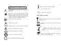
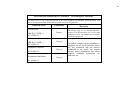
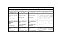
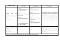
ATTENTION:
TABLE OF CONTENTS
General care of the equipment----------------------------------------------2
Explanation of the utilized symbols---------------------------------------3
Preliminary Observations---------------------------------------------------5
THIS
MANUAL
OF
INSTRUCTIONS
REFERS
TO
NEUROVECTOR V 2.0 EQUIPMENT
MANUFACTURED BY IBRAMED
NEUROVECTOR V 2.0 Description--------==-------------------------6
NEUROVECTOR V 2.0 – Essential Performance---------------------6
NEUROVECTOR V 2.0 – Electrical AC Input------------------------7
Interferential Currents - Introduction--------------------------------------8
Static Interferential Field--------------------------------------------------11
Dynamic Interferential Field----------------------------------------------13
Pre-modulated Interferential Currents-----------------------------------15
AMF Selection (treatment frequency)-----------------------------------16
PLEASE
READ
THIS
MANUAL
CAREFULLY BEFORE USING THE
EQUIPMENT AND ALWAYS REFER TO
IT
WHENEVER
DIFFICULTIES
APPEAR.
KEEP
THIS MANUAL
ALWAYS AT HAND.
NEUROVECTOR V 2.0 –
Controls, indicators and usage instructions-----------------------------17
NEUROVECTOR V 2.0 – BIPOLAR Mode---------------------------31
NEUROVECTOR V 2.0 – TETRAPOLAR Mode--------------------33
Cautions, Indications and Counter-indications-------------------------35
Electrodes – Recommendations------------------------------------------36
Environmental Protection--------------------------------------------------37
Cleaning of the Electrodes / Maintenance-------------------------------38
Warranty and Technical Assistance--------------------------------------21
Sales Points------------------------------------------------------------------40
NEUROVECTOR V 2.0 Operation Manual – 2st edition (09/2009)
Warranty Term--------------------------------------------------------------41
Trouble spotting-------------------------------------------------------------43
Accessories and Technical Characteristics------------------------------44
Electromagnetic Compatibility-------------------------------------------47
Free Technical Assistance Contract--------------------------------------53
the input plug from socket when not using the equipment for a long
period of time.
1
2
General Care of the Equipment
ATTENTION
RISK OF ELECTRIC SHOCK
DO NOT OPEN
The NEUROVECTOR V 2.0 does not need special
installation measures or care. We suggest that you:
♦ Avoid places subject to vibrations.
The lightning bolt symbol inside a triangle is a
warning about the presence of “dangerous voltage”,
without insulation in the internal part of the
equipment which may be strong enough to cause
risk of electrical shock.
♦ Install the equipment on a firm and horizontal surface,
in a site with perfect ventilation.
♦ In case of a built-in cabinet, verify that there is no block for free
circulation of air in the rear part of the instrument.
♦ Do not lay it on carpets, rugs, cushions or other soft surfaces that
can obstruct the ventilation.
♦ Avoid humid, hot and dusty places.
An exclamation mark inside a triangle alerts the user
about the existence of important operation and
maintenance instructions (technical service) for this
equipment.
♦ Place the cable in order to leave it free, out of places where it can
be trodden on, and do not place any furniture over it.
♦ Do not insert objects into equipment orifices and do not place
recipients with liquid on it.
ATTENTION: To prevent electrical shock do not use the equipment
plug attached to an extension cable or to any other type of plug
except that the terminals fit perfectly in the receptacle. Disconnect
♦ Do not use volatile substances (benzene, alcohol, thinner and
solvents in general) to wipe the equipment cabinet because they
can damage the finishing. Use only a soft, dry, and clean piece of
cloth.
4
Explanation of the Symbols Used
-
- Indicates: On (with electrical power supply)
3
ATTENTION! Check and follow the instructions in
this manual.
V~
~ line
-
Equipment CLASS II. The protection against electric
shock is not based only in the basic insulation but also
incorporates additional safety precautions, such as double
or reinforced insulation, not holding grounding resources
protection or depending on installation conditions.
-
- Alternate current power line
In the Transportation Box:
-FRAGILE: The content in this package is fragile and should
be handled with care.
Equipment with BF type applied part.
-
- Volts in Alternate Current
- THIS SIDE UP: Indicates the correct position to ship the
package.
Risk of electrical shock.
IPX0 - Equipment not protected against harmful water dripping.
50ºC
- Indicates electrostatic discharge sensibility
5ºC
- TEMPERATURE LIMITS: Indicates the limit
temperatures for transportation and storage the
package.
- Indicates the start of the action (START)
- Indicates the end of the action (STOP)
- Indicates: Off (without electrical power supply)
KEEP IT AWAY FROM THE RAIN: This package
should not be shipped under rain.
6
5
5
- MAXIMUM STACKING NUMBER: The maximum
number of identical packages which can be stacked. For
this equipment, the limit stacking number is 5 units.
Preliminary Observations
The NEUROVECTOR V 2.0 is an electrical stimulator use
in therapies for interferential medium frequency currents. This
technique is noninvasive, without systemic effects, it does not cause
dependency and it does not have undesirable side effects.
As for the type and degree of protection against electrical shock, the
NEUROVECTOR V 2.0 corresponds to a BF – applied part CLASS
II of safety and protection. It must only be operated by qualified
professionals and in duly accredited medical departments The use of
these units is not intended for rooms with risk of explosion such as
anesthesia departments or the presence of an anesthetic flammable
mixture with air; oxygen or nitric oxide.
POTENTIAL ELETROMAGNETIC INTERFERENCE: As for the
limits regarding electromagnetic disturbance, Neurovector V 2.0 ist
electro-medical equipment that belongs to Group 1, Class A. The
simultaneous connection of the patient to the NEUROVECTOR V 2.0
stimulator and to surgical equipment of high frequency can cause
burns in the application area of the electrodes and it may damage the
stimulator. The operation at a short distance (1 meter for example)
from shortwave or microwave therapy equipment can produce
instability in the output of the equipment. In order to prevent
electromagnetic interference; we suggest you to use an electric
network line for NEUROVECTOR V 2.0 and a separate group for
short wave or microwave equipment. We also suggest that the patient,
o NEUROVECTOR V 2.0 and the connection cables are placed at
least at a distance of 3 meters away from the shortwave or
microwave therapy equipment
Mobile or portable radio frequency communication equipment may
produce interference and affect the performance of Neurovector V
2.0.
IBRAMED
Description of the NEUROVECTOR
The NEUROVECTOR V2.0 was designed following the
existing technical manufacturing standards for medical equipment
(NBR IEC 60601-1 NBR IEC 60601-1-2 and NBR IEC 60601-2-10).
Basic Performance: The Neurovector V2.0 is equipment for
electrical current application through electrodes in direct contact with
the patient for neuromuscular dysfunction therapy. It is a
transcutaneous muscular stimulator with microcomputer technology,
this means, it is microcontrolled. This equipment is intended for
therapies with interferential currents and medium frequency alternate
currents.
This technique is noninvasive, without systemic effects, it
does not cause dependency and it does not have undesirable side
effects. The current intensity necessary for the treatment depends on
the sensation of the patient. Thus, the treatment must start with
minimum intensity levels (very low), carefully increased until
obtaining the adequate effects of the procedure and according to the
reaction of the patient.
The importance of medium frequency alternate currents is
indisputable in electrotherapy. In the Neurovector V 2.0, these
alternate currents have an operation frequency of 2000 Hz, 4000 Hz
or 8000 Hz, that penetrate deeply in the tissues, producing a great
variety of physiological effects. They allow for high current
densities with a slight sensorial effect on the skin, becoming quite
pleasant to the patient. The danger of burns under the electrodes is
minimal. The so called interferential current is a technique in which
two medium frequency alternate currents, of different phases or
frequencies cross. The superposition of the amplitudes results in a
new frequency called “Bouncing Frequency” or “Modulated
Amplitude Frequency” (AMF).
We highlight the following characteristics of the NEUROVECTOR
V 2.0:
•
Operation via touch keyboard with the information demonstrated
on an alphanumerical liquid crystal display.
• Interferential stimulation mode:
Bipolar (pre-modulated)- continuous or surge mode;
Tetrapolar- normal or with manual or automatic vector
exploration.
7
•
•
•
•
Possibility of selecting the automatic sweeping range of the
Modulated Amplitude Frequency - SWEEP (also known as
∆ AMF).
Possibility of selecting the carrying frequency at 2000 Hz, 4000
Hz or 8000 Hz.
On, Off, Rise and Decay for muscle exercise (surge mode).
Possibility of selecting the application time, automatically
disconnecting the emission current at the end of the program.
NEUROVECTOR V 2.0
ELECTRICAL INPUT
NEUROVECTOR V 2.0 is a CLASS II monophasic
equipment with BF applied part of safety and protection.
Functioning in network voltages in the range of 100 – 240
volts 50/60 Hz consequently, it is not necessary to be concerned
regarding the voltage of the local power supply line. Just plug in the
equipment to the “power outlet” and the equipment will perform,
automatically, the selection to 110/220 volts.
The connection cable to the electric line is detachable.
The equipment uses the line plug as a resource to separate
electrically the circuits of the power line in all the poles.
ATTENTION: On the rear part of the Neurovector V 2.0,
is located the protection fuses. To replace them, turn the equipment
off, unplug it from the power outlet and, with a small screwdriver,
take the protective lid off, disconnect the fuse, perform the
replacement and put the lid back to its original place.
Install the correct fuses: Use a fuse for 5.0A
nominal current, 250V~ operation voltage
and rapid action 20AG model (50A rupture
current).
SECURITY RISKS MIGHT OCCUR IF THE EQUIPMENT IS
NOT PROPERLY INSTALLED.
NOTE: There are dangerous voltages inside them. Never open
the equipment.
8
INTERFERENTIAL CURRENTS - Introduction
Resistance of the Skin:
As it is already known, our biological systems respond to low
frequencies, this means, within an approximate range of 0.1Hz to
200Hz. This is called the biological reach range. Therefore, the
current stimulators work within this range. However, the human skin
offers high resistance to the passage of these low frequency currents
and with a relatively long duration of the pulse. Since the resistance
of the skin is high, a higher voltage shall be applied to the skin to get
the correct and necessary current into the tissues. The higher the
applied voltage, the higher will be the current intensity and the
stimulus may become unpleasant to the patient. If the resistance of
the skin is lowered, a lower voltage will be necessary. However, the
skin is a complex biological resistance; it is hard to predict the exact
value of the resistance in any part of the body. The skin acts as a
linear resistance and also as a condenser. The resistance offered by a
condenser to the passage of alternate current is called capacitive
reactance. It acts in combination with the linear resistance of the skin.
The capacitive reactance has a useful feature, this means, it decreases
as the frequency of the applied current increases. Consequently, if
we had a current of higher frequency, the resistance of the skin will
decrease, providing a more efficient stimulation. Additionally, higher
frequencies have a shorter pulse duration, leading to a more pleasant
stimulus. In electrotherapy, the “spectrum" of the frequency can be
divided thus:
High Frequency : > 100,000 Hz (100KHz)
Medium Frequency : 1,000 to 100,000 Hz (1KHz to 100KHz)
Low Frequency : > 1,000 Hz (1KHz)
9
If we increase this frequency, this resistance of the skin will
dramatically drop. Research shows that the resistance of the skin is
very low when the applied alternate current is in the range of 2,000
Hz to 10,000 Hz. These alternate currents of Medium Frequency of
operation of (2,000 Hz to 10,000 Hz) penetrate deeply into the tissues,
producing a great variety of physiological effects. Since in this case
the resistance of the skin is low, high current densities with low
sensorial effect on the skin are possible, becoming quite pleasant for
the patient. The danger of burns under the electrodes is minimal.
However, we have a problem. As it has been seen, in order to
lower the resistance of the skin, we use Medium Frequency current in
the range of 2,000Hz to 10,000 Hz.
However, it is not known that the “biological
range”presented by the tissues is from 0.1 Hz to 200 Hz (Low
Frequency) ?
The Medium Frequency currents are very far from the
biological range of the tissues!
And now?
10
of the two currents generated in each channel. In interferential
therapy, AMF (treatment frequency) corresponds to the frequencies
normally used in electrotherapy with low frequency. Consequently,
we have the advantages of medium frequencies (4,000 Hz –
resistance of the lower skin) and are well within the biological range
0.1 to 200 Hz (AMF).
AMF = f2 - f1
f2 = 4,050 Hz
and
f1 = 4,000 Hz
AMF = 4,050 – 4,000 = 50 Hz (treatment frequency)
C
A
1
B
A
Stimulation by INTERFERENTIAL CURRENTS:
2
B
“Interferential Current” is the phenomenon that occurs when
two or more oscillations are applied simultaneously at the same point.
In interferential therapy, two medium frequency alternate
current stimuli (4.000 Hz to 4.100 Hz for example), are applied at the
same time on the same point. One of these alternate current stimuli is
fixed at 4,000 Hz while the other stimulus can be selected from 4,001
Hz to 4,100 Hz. A third frequency called “Bouncing Frequency” or
“Modulated Amplitude Frequency (AMF)” is created where these
two medium frequency stimuli cross.
For example: The interferential current equipment has two
output channels. Channel 1 is fixed at 4,000 Hz and channel 2 is
variable from 4,001 Hz to 4,100 Hz, this means, this channel 2
frequency is selected by the operator within this range from 4,001
Hz to 4,100 Hz.
Then supposing that the frequency selected on channel 2 is
4,050 Hz and the frequency on channel 1 is fixed at 4,000 Hz, a third
frequency (AMF) of 50 Hz will be generated on the intersection
points
C
A
C
B
1 ciclo da frequência de
batimento
Figure 1 – In the above diagram, 1 is the channel fixed at 4,000 Hz and 2 is
the channel where the frequency was selected at 4,050 Hz. At certain points,
the two phases will be identical (A and B) and in such situations, the
resulting sum will produce an increase in the total amplitude. In point (C),
the two currents are equal and opposite, canceling each other. The
“envelope” (dotted line) shows the shape of the bouncing frequency cycle.
The number of envelopes per second represents the AMF, this means, 4,050
Hz – 4,000 Hz = 50 Hz (treatment frequency).
11
12
STATIC INTERFERENTIAL FIELD
(normal or standard tetrapolar)
In interferential treatment known as normal or standard
tetrapolar, four electrode are necessary (two per channel). These four
electrodes are usually applied on the patient as shown in figure 2.
Circuit 2
Circuit 1
Circuit 1
Direction
Of the
interferenti
al effect
Circuit 2
Figure 2
The two circuits are placed in the best possible diagonal
manner. The interferential effect occurs only in the shaded areas.
Meanwhile, the shaded areas in the figure are applied only for
homogenous tissue.
In the majority of clinical situations, the tissues of the patient
are not homogenous and the area represented in the figure will
probably be modified.
The field seen in figure 2 is known as the Static
Interferential Field. At this point, it is important to make some
considerations regarding the application of the electrodes in
interferential therapy. An effective treatment only occurs when the
patient perceives a dominant sensation concentrated in the area where
the problem is found. In other words, the patient will feel a
significant pricking sensation around and in the area where the
problem is found.
An adjustment in the position of the electrodes on the skin is
important to achieve the best results. One of the reasons found for
the results not to be satisfactory in interferential therapy is the
inadequate position of the electrodes. The patient should experience
a pleasant prickling sensation (as “soft as a needle prick”). It is
possible for the patient to experience a sensation under the electrode;
but must also always feel the possible “prickling” sensation in the are
where the problem is located.
The “leaf shaped” model shown in figure 2 represented the
so called Static Interferential Field and is commonly used to
describe the area of interferential effect. However, there are other
aspects in the shape and distribution of this field. Since there is no
practical way to measure the interferential effect area, the
professional must rely on the report of the patient regarding the area
and stimulation extent.
It is relatively easy to find the effect when the four electrodes
are close to each other; but this serves as a superficial comparison of
the treatment. There are mathematical methods to describe the effect
of interference and its distribution, but their use is clinically limited
because of certain situations encountered by the patient.
13
DYNAMIC INTERFERENTIAL FIELD
(tetrapolar with manual or automatic vector)
The described Static Interferential Field represents the
tetrapolar—normal or standard mode or application standards of
interferential currents. Over the years, this basic process underwent
interesting developments. The most significant was the so-called
“Manual Vector” and “Automatic Vector”. This Manual or
Automatic Vector mode is nothing more than the flow of current
produced increases the two circuits (channels) together in a vectorial
manner. A better technical description would be the concept of de
“rotational” or “dynamic” vector system. The concept of “dynamic”
vector system is basically simple, this means, it involves the rotation
of the Static Interferential Field of zero to approximately 45 degrees
and back to zero again. The field influence area in the tissue
becomes more extensive than in the Static Interferential Field.
This “movement” is rhythmically produced by the design of
the currents, altering the position of the maximum stimulation area.
Figure 3 illustrates this principle.
14
In the case where the patient presents not well localized
symptoms, the dynamic vector system (automatic vector) can be a
useful method for this problem. However, it should be understood
that, since the field of influence is “sweeping” the tissues, a part pf
the treatment time can not be spent on the injury.
The “automatic vector” (dynamic vector) system should not
be seen as a shortcut to allow for the therapeutic treatment of the
problem without locating it correctly. With the electrodes well
placed before the start of the treatment, the dynamic vector systems
may increase the efficiency of the treatment. However, this treatment
efficiency depends largely on the correct placement of the electrodes.
It is worth emphasizing here, that the effects seen in figure 3 occur in
homogenous medium. It is difficult and almost impossible to
accurately predict the pattern of the interferential effect on the patient
subject to the static or dynamic interferential fields. There is no
evidence to suggest that the manual or automatic vector” mode is
significantly better than the "normal or standard" mode.
EQUILIBRIUM OF THE CIRCUITS (“BALANCE OF THE
CHANNELS")
Circuit 2
100%
Of Interferential effect
Circuit 1
1
45º
2
Figure 3
These arrows
Indicate
the
placement of
the
interferenti
field
The “Balance of the Channels” is used in normal Tetrapolar
Interferential mode (static interferential field). To achieve a
maximum therapeutic effect, it is necessary to ensure that the current
flowing between the two channels are equal. Since the body tissues
are not homogenous, it is necessary to adjust the current of the
channels so that they are equilibrated (“balanced”). Some equipment
perform this “balance” automatically, for others, it must be adjusted
externally by the therapist through a control called balance or
adjusting the same current in the two channels.
The Neurovector V 2.0 uses constant output current
technology for the patient. Therefore the balance is achieved by
placing the same current (mA) in the two channels. Remember that
the level of current to be applied can be different for each patient.
Consequently, the intensity should be “felt”, however it should be
pleasant to the patient.
Even in normal Tetrapolar mode, the Neurovector V 2.0
allows the performance of manual operation (MANUAL VECTOR),
where the therapists manually rotates the interferential field “trying
to localize”, according to what is reported by the patient, the exact
location of the problem.
16
15
For this, simply unbalance the channels, this means, leaving a
channel with lower or higher current than the other. For example:
Suppose that there is a current intensity of 30 mA in channel 1 and 30
mA in channel 2 (equilibrated circuit, balanced). If you decrease and
increase only channel 2, you will be “rotating” the vector. In the
Neurovector V 2.0, you can also select the automatic vector
stimulation mode, where the equipment will complete the “rotation of
the vector” automatically. Remember that the “manual vector” or
“automatic vector” techniques are valid only in normal Tetrapolar
Interferential mode.
PRE-MODULATION INTERFERENTIAL CURRENTS
(bipolar)
It is possible to emit interferential currents to the patient
using two electrodes instead of the conventional four. In this system,
the two currents are combined inside the equipment and transmitted
to the patient through two electrodes. There is a significant different
between this technique and tetrapolar-normal mode which uses four
electrodes.
In conventional mode (tetrapolar-normal), the
interferential current is produced endogenously (inside, deeply) in the
patient. In bipolar mode (pre-modulated) the interferential current is
applied through two electrodes to the skin of the patient. It is
unlikely that there is a clinical difference between the two methods
other than the obvious ease of application in pre-modulation mode.
For many situations, the pre-modulated mode is mostly selected, for
example: in muscle stimulation.
The equipment that have the Bipolar mode (pre-modulated),
normally require the use of only two channels. The terms “two
poles” or “bipolar” can be misleading, because this can imply two
different poles. As in interferential therapy, alternate currents are
used (without a fixed polarity), the term "pre-modulated" or "precombined" more clearly describes the application technique.
AMF CONTROL – Treatment frequency (bouncing frequency)
AMF, also known as bouncing frequency or treatment
frequency, can be controlled by two basic methods known as
In
“Continuous” (constant) and “Sweep” ( ∆ AMF) mode.
Continuous (constant) mode, the equipment generates a unique
bouncing frequency that can be selected by the
operator. In this method, the equipment generates a constant
difference in the frequency between the two channels. For example:
as already mentioned, the frequency in one channel is always 4,000
Hz and the frequency in the other channel varies from 4,001 Hz to
4,100 Hz. In Continuous (constant) mode, the operator selects a
frequency of 4,050 Hz, the equipment generates a different between
the two channels (4,050 – 4,000), this means a fixed treatment
frequency – AMF (bouncing frequency) of 50 Hz.
A more useful method for controlling the bouncing frequency
is “Sweep” ( ∆ AMF) mode. In this case, the equipment
automatically generates the bouncing frequency inside a pre-selected
range. This pre-selected range is known as “frequency extension”.
The word extension can be interpreted as range of treatment
frequency. This frequency range is automatically and rhythmically
increased and decreased inside a pre-established AMF range.
For example: An AMF (basic treatment frequency) of 20 Hz is
selected and an extension, this means, Sweep ( ∆ AMF) of 50 Hz is
required. The current released to the patient starts with an AMF
(treatment frequency) of 20 Hz and (with an extension of 50 Hz)
passing successively through the other frequencies until a frequency
of 70 Hz is reached, then gradually decreasing until 20 Hz. This
process is repeated automatically.
The “SWEEP” mode is widely used for avoiding adaptation. A
“large” extension will prevent adaptation more efficiently than a
"close" extension. Using a large extension of frequency, notable
sensations and/or contractions occur.
Selection of AMF or Treatment Frequency: The selection of AMF
depends on the nature, stage, severity and location of the problem.
The sensations experienced by patients in different AMF should be
considered. Higher frequencies are perceived as “pleasant and
lighter”. Higher AMF (75 Hz to 200 Hz) are recommended for acute,
high pain or hypersensitivity problems.
When the patient
demonstrates a certain fear to electrostimulation, a high AMF should
be used at the start of the treatment. In low frequencies the sensation
is more “rough and heavy”. Frequencies between 25 Hz to 50 Hz
tend to produce contractions (tetanic).
In muscle contractions, chronic or sub-acute problems, a low AMF is
more appropriate. Low frequencies of 50 Hz produce pulsed and
fibrillated contractions.
17
NEUROVECTOR V 2.0 –
Controls, indicators, and operation
18
19
20
How to use the Neurovector V 2.0:
1- ON/OFF switch.
2- Luminous indicator of the “connected” condition.
3- BACK/NEXT keys.
4- SET+ and SET- control keys.
As described previously, all the parameters are programmed by touch
screen and indicated in the displayed crystal screen. Thus, the
necessary steps to operate the equipment are listed as follows.
Liquid crystal screen:
5- Alphanumerical liquid crystal DISPLAY
6- STAR/STOP keys
7- PROGRAM control key.
8- UP and DOWN control keys – channel 1 intensity.
9- UP and DOWN control keys – channel 2 intensity.
10-
luminous (yellow) indicators of channel 1 and 2 of the
presence of an output current intensity for the patient
that
may present a resistance to a charge of 1000 ohms, a
tension higher than 10 V or a current higher than 10 mA.
In SURGE bipolar interferential mode, this indicator "will flicker" in
accordance with the On Time, OFF Time, Rise and Decay times
11- Connection of output cables to the patient – CHANNEL 1 and
CHANNEL 2.
12- Power cable port to be connected to the power supply line.
Field designed for the selection of the mode
of interference: Tetrapolar (TP) or Bipolar
(BP).
Field intended for the selection of the carrying
frequency at 2000 Hz, 4000 Hz or 8000 Hz.
Field intended for the selected of the vacuum
operation mode:
13- Fuse rack.
14- General characteristics board.
15- Tag with the characteristics of the output current of the
NEUROVECTOR V 2.0.
Field intended for the selection of the SWEEP
(▲AMF) frequency range from 1 to 100Hz.
Field intended for the selection of the
modulation frequency (bouncing frequency):
1 to 100Hz.
Field designed for the selection of the mode
of stimulation: normal Tetrapolar; Tetrapolar
with automatic vector; continuous Bipolar and
surge Bipolar.
21
22
When in Surge Bipolar mode - field designed for the
selection of the parameter PULSE RISE TIME (time
to go from rest to maximum contraction – pulse
increase gradient), variable from 1 to 9 seconds.
Note that the MODE – TP (TETRAPOLAR field is
flickering.
When in Surge Bipolar mode - Field designed for the
selection of the parameter CONNECTION TIME (time
of sustentation of the maximum muscle contraction),
variable from 1 to
60 seconds.
2 o Step: BACK and NEXT (3) control keys: These keys are used to
select the necessary treatment parameters. As you press the NEXT
key, you will be advancing to another parameter. As you press the
BACK key, you will be returning to the previous parameter. Note
that at each selection you choose through the BACK and NEXT keys,
the chosen parameter will be in flashing mode.
When in Surge Bipolar mode - field designed for the
selection of the parameter PULSE DESCENT TIME
(time to go from maximum contraction to rest – pulse
decrease gradient), variable from 1 to 9 seconds.
3 o Step: SET + and SET - (4) control keys: These keys are used to
choose the marks of each necessary parameter to the therapy.
When in Surge Bipolar mode - field designed for the
selection of the parameter REST TIME (time of the
muscle contraction), variable from 1 to 60 seconds.
Field designed for the selection of the parameter
APPLICATION TIME (TIMER). Allows for the
selection of an application time of 1 to 60 minutes.
1 o Step: Turn on – turn off key (1). When turning on the equipment,
the liquid crystal display (5) will show, for a few seconds, the
following presentation message:
MODE
SWEEP MODE
CARRIER
SWEEPFREQ.
( Hz )
SWEEP MODE
AMF( Hz)
IBRAMED
STIM. MODE
RISE
ON
DECAY
SWEEP FREQ.
( Hz )
NEUROVECTOR v 2.0
OFF
After this presentation, a sound signal (“beep”) will be heard
and the screen (5) will start operating, now indicating:
SWEEP MODE
SWEEP FREQ.
( Hz )
SET+
Increasing values.
SET-
Decreasing values.
4 o Step: START / STOP (6) control keys - Once the parameters and
their values are respectively selected (as described in the previous
paragraphs), press the START key. Observe that the parameters stop
to flicker. At this moment the program will start. Now choose the
current intensity necessary for the treatment. If you wish to interrupt
the application, just press the STOP key. The current will be
interrupted and the parameters will flicker again in order to perform a
new programming. At the end of the programmed time you will hear
a sound signal (several "beeps") and the current will stop. Press the
STOP key so that the sound signal is disconnected and for the
equipment to go back to the programming condition. As you can see,
there are two functions in the same keyboard. START – beginning
the treatment. STOP – stop the treatment.
23
24
NOTE:
1- If during the programming you forget to enter the
application time, a sound signal (“beeps”) will also be emitted,
indicating an operation error. At this moment the screen (5) will
display:
SWEEP MODE
SWEEP FREQ.
( Hz )
Press the STOP (6) key and note that the error message has
disappeared. Then, select the necessary time and continue your work.
2- Once the “Start” is pressed for the treatment, the BACK
and NEXT (3), SET+ and SET- (4) keys do not operate any more,
new values for the parameters during the application cannot be
selected and chosen. In this case, the "Stop” key must be pressed in
the treatment and then, modify the parameter.
3 – If the operator wants to interrupt the treatment or choose
a new time after the end of application alarm sounds, they will need
to press the STOP (6) key again for the equipment to go back to the
condition of programming new parameters. Thus, the equipment is
ready to receive a new programming.
4- When the type of stimulation selected (STIM. MODE) is
SURGE, the luminous indicators of channels 1 and 2 “flicker”
according to the Rise, On, Decay and Off times selected (onindicators turned on, off-indicators completely turned off).
We
suggest increasing the intensity of the channels only when the LEDs
are turned on (maximum contraction). The SURGE mode operates
only when the interferential mode of Bipolar (BP) is selected.
5- In case the electrical network stops (“lack of electricity”),
the equipment will be disconnected automatically. Thus, when the
network energy comes back, you must execute again the
programming necessary for the treatment.
As it has been seen up to this point, the Neurovector V 2.0 panel is
self-explanatory, only a few minutes of use is enough to become
familiarized with its programming.
NOTE: We suggest that the preparation procedures for the
patient and the placing of the electrodes are performed before
connecting and programming the instrument.
Example 1: Let us suppose that the clinical practice or existing
literature suggests the BP (Bipolar) interferential mode with Surge
stimulation mode, with the following parameters for a certain
pathology:
- Carrying frequency (Carrier) = 2 KHz
- Modulation frequency (AMF) = 50 Hz
- Sweeping mode (sweep mode) = off
- rise = 2 seconds
- on = 5 seconds
- decay = 2 seconds
- off = 10 seconds
- treatment time = 20 minutes
Turn on the equipment. The “default” program described on page 21
will be executed. Note the cursor flickering on the MODE field:
SWEEP MODE
SWEEP FREQ.
( Hz )
¡- Select the BP (Bipolar) interferential mode:
Press the SET+ key until the MODE field displays BP. At this time,
the liquid crystal screen will indicate:
SWEEP MODE
SWEEP FREQ.
( Hz )
25
26
2- Select the Surge stimulation mode:
Press the BACK key until the curser is positioned (flickering) on the
STIM.MODE field. Now press the SET+ key until the word Srg. Is
displayed.
At this time, the liquid crystal screen will indicate:
Now press the START key for the start and execution of the selected
programming. Note that the "flickering" cursor disappears and the
liquid crystal screen will indicate the information regarding the
intensity of the
current.
SWEEP FREQ.
SWEEP MODE
( Hz )
SWEEP FREQ.
( Hz )
3- Now select the other parameters – Carrying frequency (Carrier) =
2 KHz, modulation frequency (AMF) = 50 Hz, sweeping mode
(sweep mode) = off, rise = 2 seconds, on – 5 seconds, decay = 2
seconds, off = 10 seconds, treatment time = 20 minutes:
Press the NEXT key until the cursor is positioned (flickering) on the
RISE (s) field. Now press the SET+ key until 2 seconds is displayed
in this field. Proceed in the same manner for the other fields and
always use the NEXT and SET+ keys to select the other parameters.
Note: In case the value is accidentally exceeded, use the SET- key to
decrease the value.
Very well, the programming of all the necessary parameters was
selected. The information displayed in the liquid crystal screen will
be:
SWEEP MODE
SWEEP MODE
SWEEP FREQ.
( Hz )
Now press the UP or DOWN keys of the channel that is being used to
select the current intensity necessary for the treatment. At the end of
the programmed time, the emission of current will be interrupted and
a sound alarm will indicate the end of the treatment. Press the STOP
key to stop the alarm. Now the equipment can be disconnected or
will be ready to repeat the programming or perform a new
programming.
Example 2: Let us now suppose that clinical practice or existing
literature suggests certain pathology for TP (Tetrapolar) interferential
mode, with Sweep sweeping mode = with frequency
range
of Sweep (▲AMF) = 30 Hz and AMF = 40Hz. We use a carrying
(Carrier) frequency = 8 KHz, modulation frequency = 40 Hz, normal
stimulation mode and treatment time = 10 minutes.
Connect the equipment", and the "default" programming described
on page 21 will be executed. Note the cursor flickering on the MODE
field:
SWEEP MODE
SWEEP FREQ.
( Hz )
27
28
1- Always using the BACK/NEXT and SET+/SET- keys, select the
parameters necessary for the treatment.
Thus, the liquid crystal screen will indicate:
Control key PROGRAM (7) (Program) – is the key which allows
the operator to select treatment protocols. Are quick treatment
programs, that are stored in the equipment memory.
SWEEP MODE
SWEEP FREQ.
( Hz )
We are going to provide a small example.
Turn on the equipment as described on page 21. Press the PROG key.
The liquid crystal screen will display:
SWEEP MODE
SWEEP FREQ.
( Hz )
Note: In the SWEEP MODE field, note the small arrow that indicates
which program is selected.
Very well, the programming of all the necessary parameters was
selected. Now press the START key for the start and execution of the
selected programming. Note that the "flickering" cursor disappears
and the liquid crystal screen will indicate the information regarding
the intensity of the
current.
SWEEP FREQ.
SWEEP MODE
( Hz )
Now press the UP or DOWN keys of the channel that is being used to
select the current intensity necessary for the treatment. At the end of
the programmed time, the emission of current will be interrupted and
a sound alarm will indicate the end of the treatment. Press the STOP
key to stop the alarm. Now the equipment can be disconnected or
will be ready to repeat the programming or perform a new
programming.
Observe that the procedure to program the equipment in example 1 is
almost identical to example 2. Consequently, the procedure to
program the parameters of Neurovector V 2.0 is always the same, it
is only necessary to practice a little and acquire a habit to use it.
Using the SET+/SET- key you will be able to select 8 set treatment
programs (protocols). These are:
1- Muscular lesion - acute phase: Carrier 4000Hz, AMF 5Hz and
∆AMF 20Hz, Sweep
(6/6), Tetrapolar technique, Stimulation
Intensity, Sensorial intensity, Time – 20 minutes. Mechanism
activated for pain modulation release of endogenous opioids.
2- Muscular lesion – sub-acute and regenorative phase: Carrier
4000Hz, AMF 50Hz and ∆AMF 100Hz, Sweep
(5/1),
Tetrapolar technique, Stimulation Intensity, Sensorial intensity,
Time - * duration of associated technique. * This therapeutic protocol
involving interferential therapy should be used together with
cinesiotherapeutic techniques such as extending, transversal massage,
stretching or manual therapeutic techniques. Mechanism activated
for pain modulation pain tolerance.
3- Delayed muscle pain – post physical activity: Carrier 4000Hz,
AMF 10Hz and ∆AMF 20Hz, Sweep
(1/1), Tetrapolar
technique, Stimulation Intensity, Sensorial intensity, Time – 20
minutes. Mechanism activated for pain modulation release of
endogenous opioids.
29
30
4- Increase of cutaneous blood flow: Carrier 4000Hz, AMF 10Hz
and ∆AMF 10Hz, Sweep
(6/6), Tetrapolar technique (the
electrodes must be fixed on the skin near to the ganglia nervous of
the sympathetic nervous system, preferably parallel to the vertebral
column), Stimulation Intensity, Sensorial intensity, Time – 12
minutes. Mechanism activated for the increase of blood flow:
reduction of sympathetic tone on the wall of the peripheral vascular
endothelium with subsequent vascodilation. This protocol can be
used in situations of peripheral vascular illnesses or previous
therapeutic techniques such as massotherapy or lymphatic drainage.
Bibliography reference – J. Gareth Noble, Gail Helderson, A. Fiona
L. Cramp, Deirdre M. Walsh, Andrea S. Lowe. The effect of
interferential therapy upon cutaneous blood Flow in Humans.
Clinical Physiology 20(1): 2 – 7, 2000.
5- Modulation of acute pain: Carrier 4000Hz, AMF 60Hz and
∆AMF 100Hz, Sweep
(6/6), Tetrapolar technique, Stimulation
Intensity, sensorial intensity, Time – 20 minutes. Mechanism
activated for pain modulation pain tolerance. Modulation of pain in
these situations is due to the time of use of the therapeutic electrical
current.
6- Modulation of chronic pain: Carrier 4000Hz, AMF 5Hz and
∆AMF 20Hz, Sweep
(5/1/5), Tetrapolar technique, Stimulation
Intensity, sensorial intensity, Time – 30 minutes. Mechanism
activated for pain modulation release of endogenous opiodes.
Analgesia started after 10 to 20 minutes after the end of the
stimulation and remains active for a period of 2 to 3 hours.
7- Modulation of pain in patients with osteoarthritis of the knee:
Carrier 4000Hz, AMF 3Hz and ∆AMF 7Hz,
Sweep
(6/6), Tetrapolar tehcnique, Stimulation intensity,
sensorial intensity, Time – 40 minutes. Mechanism activated for pain
modulation release of endogenous opiodes. Analgesia started after
10 to 20 minutes after the end of the stimulation and remains active
for a period of 2 to 3 hours.
8- Modulation of pain and control of edema in immediate post
operation of LCA ligamentoplasty, menistectomy and
condroplasty: Carrier 4000Hz, AMF 5Hz and ∆AMF 15Hz
following an AMF of 70 Hz and ∆AMF 80Hz, Sweep
(6/6),
Tetrapolar technique, Stimulation Intensity, sensorial intensity, Time
– 30 minutes. Mechanism activated for pain modulation pain
tolerance and release of endogenous opioids. Analgesia started after
10 to 20 minutes after the end of the stimulation and remains active
for a period of 2 to 3 hours.
9- Functional recovery for muscles with predominance of type I
fibers (RF pred. Type I muscles): carrier 2000 Hz, AMF 5Hz and
∆AMF 7Hz, Sweep
1/1, Bipolar (pre-modulated) technique,
intensity above the motor threshold time equal to 20 minutes or the
number of desired contractions.
10- Functional recovery for mixed Iia and Iib muscles (RF mixed
IIa and IIb muscles): carrier 2000 Hz, AMF 35Hz and ∆AMF 15Hz,
Sweep
1/1, Bipolar (pre-modulated) technique, intensity above
the motor threshold time equal to 20 minutes or the number of
desired contractions.
11- Functional recovery for muscles with predominance of type
IIb fibers (RF pred. Type IIb muscles): carrier 2000 Hz, AMF
50Hz and ∆AMF 20Hz, Sweep
1/1, Bipolar (pre-modulated)
technique, intensity above the motor threshold time equal to 20
minutes or the number of desired contractions.
The development of the treatment must be performed by modifying
the modulations times in gradient: rise, decay, on and off. You
should always try to increase the contraction time by maintaining or
increasing the rest time. The rise and decay are based on the
discretion of the therapist.
Once a protocol is selected, press the PROG key again. Now press
the START key. Select the intensity necessary for the treatment.
31
NEUROVECTOR V 2.0 – Bipolar Interferential mode:
1- Possibility of selecting AMF (treatment frequency) from 1 Hz to
200 Hz (1 Hz steps).
2- Sweep or ∆ AMF (AMF sweeping range) – With the passing of
time, a patient subjected to electrical stimulation, will soon feel it
with less intensity, and can even stop feeling the sensation caused by
the current. This process is called “accommodation” and occur due
to the sensors being stimulated, passing information regarding the
external changes in decreasing degree. The accommodation can be
avoided by varying the AMF (treatment frequency).
SWEEP ( ∆ AMF) sweeping mode:
The AMF remains in the basic frequency for one
second and then switches abruptly to a higher
frequency in which it also remains for one second. This is repeated
automatically. This method of treatment has an aggressive effect and
becomes more aggressive if a “large” extension of AMF sweeping is
selected. An effect can be observed immediately after the treatment,
with this type of program it is superficial hyperemia. This program is
recommended for chronic and sub-acute problems.
Example: If a basic AMF of 20 Hz and an extension (sweep)
of 50 Hz is selected using this program, the AMF remains for one
second at 20 Hz, switches abruptly to 70 Hz, remains for one second
at 70 Hz, switches abruptly at 20 Hz and starts a new cycle.
The AMF remains at a basic frequency for five
seconds, passing through all the other frequencies
(inside the selected extension) in one second until
reaching a higher frequency in which it remains for 5 seconds. This
is repeated automatically. This method of treatment has softer
characteristics and more tolerated by patients with acute disorders.
32
Example: If a basic AMF of 20 Hz and an extension of 50 Hz is
selected, then using this program the AMF remains for five seconds
at 20 Hz, passes through all the frequencies within the selected
extension (21 to 69 Hz) in one second until reaching the frequency of
70 Hz, remains for five seconds at 70 Hz, goes back through all the
frequencies again (21 to 69 Hz) in one second until reaching 20 Hz
again and starts a new cycle.
The AMF is never “stationary” as in other programs. It
is continually varied, this means, in the first six seconds,
it increases through all the frequencies inside the
selected extension until reaching the highest frequency and decreases
immediately in the next six seconds. This is repeated automatically.
Of the three types of programs, this is the most pleasant of all. The
mode is widely used for avoiding accommodation.
Example: If a basic AMF of 20 Hz and an extension of 50 Hz
is selected, then using this program, a frequency “sweeping” starts at
20 Hz, increasing and passing through all the frequencies inside the
extension in seconds until the highest frequency of 70Hz and
immediately decreases in the following six seconds, again passing
through all the frequencies until 20 Hz and starts a new cycle.
3- STIM. MODE (Stimulation Mode):
Continuous – constant AMF: the equipment generates a unique
bouncing frequency that can be selected by the operator. In this
method, the equipment generates a constant difference in the
frequency between the two channels. In this stimulation (continuous)
mode, the Sweep program can still be used.
Srg - Once the AMF and/or SWEEP is selected, when in SURGE
stimulation mode, the equipment introduces the known “gradients”,
rise, on, decay e off .
Note: It is worth remembering that Continuous or Srg modes operate
only in the technique with two electrodes (Bipolar) and is generally
used for strengthening muscle.
34
33
4 - Carrier – Carrying frequency:
Reminders:
The frequencies of 2KHz, 4KHz and 8KHz can be selected.
Clinical use has demonstrated that frequencies approximated at 2,000
Hz produce greater motor activity. The current is less soft and
produces more stimulation at a muscular level. A frequency of 2KHz
should be used only in painful conditions. As a general rule, all other
applications use a frequency of 4KHz (4,000Hz) or 8KHz (8,000Hz).
NEUROVECTOR V 2.0 – Tetrapolar Interferential Mode:
1- The electrode cables fixation connector has screws which must be
fixed to the output connector (11) located on the equipment panel.
For a perfect electrostimulation, always tighten the screws of the
fixation of this connector.
2- To remove the banana clips of the electrodes, just pull them from
their protective covering. Never pull the cable.
- AMF and Sweep ( ∆ AMF) equal to bipolar mode.
- Possibility of selecting Tetrapolar interferential modes: Normal
(Standard), Manual Vector (disbalance channel) or Automatic
Vector (automatic vector). See page 14/15 of this manual.
Notes: Remember that, to execute Tetrapolar mode with Manual
Vector, the channels must be unbalanced (different current
intensities). It is the different current intensity that “rotates” the
vector.
In interferential current therapy, the bipolar mode is preferred,
because in this case, the modulation depth is always 100%. In
tetrapolar mode, the modulation depth can vary between 100% to
45%. In interferential therapy, modulation depth of 100% is very
important because it guarantees an optimum stimulation effect. In
practice, it is easier and faster to place two electrodes than four. For
these reasons, the bipolar method is preferred.
The tetrapolar method is used for large areas. The vector
technique produces a stimulation effect inside a large area. If the
location of the problem is clear, the manual vector method is
preferred. Thus, the unbalance of channels is used to achieve a
modulation depth of 100% in the area in question. Not having a
specific location, the method used should be automatic vector, which
will “pass” through the area in question.
3- We suggest that the preparation procedures for the patient and the
placing of the electrodes are performed before connecting and
programming the instrument.
4- The technique used in the treatment for interferential currents is
noninvasive, without systemic effects, it does not cause dependency
and it does not have undesirable side effects. The current intensity
necessary for the treatment depends on the sensation of the patient.
Thus, the treatment must start with minimum intensity levels (very
low), carefully increased until obtaining the adequate effects of the
procedure and according to the reaction of the patient.
Precautions: Interferential therapy is not a dangerous treatment
method. However, we would like to stress the following cautions:
-
Diathermy equipment interference: it is extremely important that
the professional knows the danger in the use of the equipment
with current such as interferential close to shortwave diathermy
units. The radio frequency emitted by the short waves can
35
-
change the characteristics of the interferential current, causing
risk to the patient. We suggest a distance of at least 2 to 3 meters
between the two equipment.
When using high densities of current, always verify there are no
reactions with the skin of the patient. These reactions can occur
if the size of the electrode is inappropriate (small).
Indications:
-
Pain relief – acute and chronic.
Reduction of acute and chronic edema.
Muscle re-education and strengthening.
Reduction of muscle spasms.
Improvement in the operation of abdominal organs, particularly
in the treatment of incontinence.
Stimulation and improvement of superficial and deep circulation.
General curative effect.
Counter-indications:
- Fever conditions.
- Tumor areas (cancer).
- Purulent infection areas.
- Implanted Electronic Device: it is recommended that patients with
an implanted electronic device (for example, a cardiac pace maker)
not to be subject to stimulation, unless a specialized medical opinion
has been previously obtained.
- Menstruation
- Areas with large open wounds.
- Hyper-sensitivity to electrical stimulation.
- Children under 10 year old.
- Elderly, senile patients.
36
ELECTRODES - RECOMMENDATIONS
As already seen, the NEUROVECTOR V 2.0 enables
transcutaneous neuromuscular stimulation with Interferencial
currents.
For this we use special rubber silicone electrodes that are
provided with the equipment.
The size (area in cm 2 ) of the electrodes used in
electrostimulation is very important;
-
-
-
-
We recommend to use only electrodes that are provided as
accessories of NEUROVECTOR V 2.0 in the 30 x 50 or 50 x 50
mm. The application method of these electrodes is very simple.
Generally, the used 50 X 50 mm is perfectly accommodated on
several parts of the body, causing a deep effect on tissues and a
comfortable treatment for the patient. If a more localized effect is
required, the 30 X 50 mm electrodes can be used, however, the
effect is more superficial.
If the user wishes to use a different type of electrode, we always
recommend electrodes of larger size than those provided as
accessory.
Electrodes of lower size than those provided as accessory may
cause irritation and skin burns. If the use of these smaller
electrodes is necessary, we recommend the current density does
not exceed 2 mA effective/cm 2 . If it necessary to surpass these
values, the user must be attentive of the possible harmful effects
(NBR IEC 60601-2-10).
The maximum values of the output current for the patient,
provided by this equipment do not exceed the current density
limit specified by the standard NBR IEC 60601-2-10. Thus, if it
is necessary, the equipment can be operated in the maximum
output mode with the recommended electrodes.
Some chemical products (gel, creams, etc) can damage the
electrodes, decreasing their useful life. Always use the gel
provided as an accessory.
After using the electrodes, clean them with tap water. Always
clean the electrodes before storage.
Attention: The application of the silicone electrodes close to
the thorax may increase the risk of cardiac fibrillation.
38
37
ELECTRODES – BIOCOMPATIBILITY (ISO 10993-1): Ibramed
declares that the silicone rubber electrodes provided with the equipment
do not cause allergic reactions. These electrodes must only be placed in
contact with the intact surface of the skin, respecting time limit duration
of 24 hours of contact. There is no risk of harmful effects to the cells,
nor is there any allergic reaction or of sensitivity. The electrodes do not
provoke a potential irritation of the skin.
Self-adhesive Electrodes (disposable): The material used in the
manufacture of these electrodes eliminates risks and special techniques
for their elimination. We suggest to follow the instructions of the
manufacturer selected by the user.
CLEANING OF THE ELECTRODES
After using the electrodes, clean them with
tap water. Always clean the electrodes before
storage.
MAINTENANCE
Durability of the silicone rubber electrodes:
Wear of the silicone rubber electrodes is normal with time and use.
A worn electrode will lose uniformity in the conduction of electrical
current, giving a sensation that the equipment is weak. Electrical
conduction points may also appear, where the current density will be
very high which may cause an uncomfortable sensation to the patient.
Change the silicone electrodes at least every six months, even if they
have not been used or even monthly in case of intense use. When cracks
appear the electrode must be changed immediately.
Environmental Protection: IBRAMED declares that there are no
risks or special techniques associated with the elimination of this
equipment and accessories at the end of their useful lives.
We suggest that the user inspects the
equipment and performs preventive
maintenance at IBRAMED or at the
authorized technical locations each 12
months the equipment is used. As
manufacturers, IBRAMED is deemed
responsible for technical or safety
characteristics of the product only in
cases when the unit has been used in accordance with the instructions
contained in the user’s manual, and where maintenance, repairs or
modifications have been made by the manufacturer or by expressly
authorized agents, and where the components which can cause safety
risks and also where components for the proper functioning of the
equipment have been substituted, in case of repairs, with original
substitution parts.
If requested, IBRAMED will be able to provide technical
documentation (circuit layout, list of parts and components, etc)
necessary for eventual equipment repairs. However, this does not
imply a repair authorization. We do not assume any responsibility for
repairing performed without our express written authorization.
39
40
WARRANTY
SALE POINTS
IBRAMED, Indústria Brasileira de Equipamentos Médicos
LTDA, herein identified to the consumer at the address and telephone
number: Rua Milão, 50 – Amparo – SP, telephone number +55 (19)
38179633, guarantees this product for the period of eighteen (18)
months, observed the conditions of the warranty terms attached to the
documentation of this equipment.
What stupid
equipment !!
TECHNICAL ASSISTANCE
STATE
CITY
COMPANY
PHONE
Ceará
Fortaleza
Escossia e Pita
(85) 265 1331
Mato Grosso
C.Grande
SóFisio
(67) 383 0013
Minas Gerais
BH
FisioTecnica
(31) 3241 2978
Paraná
Cascavél
ISP
0800 455639
Paraná
Curitiba
ISP
0800 6433808
Rio de Janeiro
R Janeiro
HB Fisioterapia Ltda
(21) 2295 6811
ProFisiomed Ltda
(51) 3217 4439
Rio Grande Sul Port Alegre
Do not wait until you
get to this point!!! Call:
São Paulo
Piracicaba
Beatriz B. M. Ltda
(19) 3422 1066
São Paulo
Santos
Presmam Ltda
(13) 3234 7666
São Paulo
São Paulo
Carci Ind.Com Ltda
(11) 33462100
São Paulo
Araçatuba
Med Ata
(18) 624 1954
São Paulo
Amparo
IBRAMED
(19) 3807 9633
(19) 3817 9633
Please contact our technical department.
41
Warranty Term
1) Your IBRAMED product is certified against manufacture
defects, if considered the established conditions in this manual for 18
following months.
2) The period of warranty will count from the first purchase
date by the consumer, even when the product is transferred to a third
party. The replacement of parts and the cost in repairs of
malfunctions originated from manufacturing will be comprehended
in the warranty.
3) The warranty procedures will be exclusively made by
IBRAMED sales points, by IBRAMED itself or by other parties
specifically designated by IBRAMED.
4) WARRANTY DOES NOT COMPREHEND DAMAGES
WHICH COULD OCCUR TO THE EQUIPMENT IN CASE:
42
5) Legal warranty does not cover: expenses with installation
of product, installation of software, installation of microcomputer,
transport of product to the factory or sales point, labor cost, materials,
parts and adaptations necessary to the preparation of the premises
where the equipment will be used, such as: electric wiring, computer
technician expertise, masonry, hydraulic installations, grounding
system, as well as its adaptations. The warranty does not cover either
parts subjected to wear and tear such as: command switches, control
keys, handles and mobile parts, sucker applicators, application pens
for microderm abrasion, power cable, connection cables to the patient,
transducer cables, conductive silicon rubber applicators, diathermy
applicators, batteries, ultra-sonic transducer (when improper use or
its fall is proved), equipment cabinet.
6) No sales point of IBRAMED has authorization to alter the
conditions here mentioned, or to take any commitment in the name of
IBRAMED.
The equipment is not used exclusively for medical purposes.
The specifications and recommendations in the user’s manual
are not observed in the installation and use of the equipment.
Accidents or natural hazards, connection to electrical system
with inappropriate voltage, and/or excessive fluctuation or
overcharge/ overvoltage occur.
Equipment :
Serial Number :
Anvisa (M.S.) Registered:
Date of Manufacture:
The equipment is not handled properly, is not taken proper
care of, or suffers alterations or repairs made by not certified people
or companies.
Validity Period: 5 anos
There is removal or adulteration of serial number of the
equipment.
CREA - 5062850975
Any accident in transportation occurs.
Responsible Engineer: Maicon Stringhetta
44
43
NEUROVECTOR V 2.0 –
Accessories accompanying the equipment
And Now ?
TROUBLESHOTTING
What might seem to be a problem at first sight,
may not always be a malfunctioning. Therefore,
before contacting the technical assistance, check
the items described on the table bellow.
Problems
Solution
•
The equipment does not turn on 1
•
The equipment does not turn on 2
Is the power cable properly connected?
If it is not, connect it. Also check the
power outlet on the wall.
Have you checked the protection fuse?
Some IBRAMED equipment models use
external fuses. Check if they are
properly connected. Check also if the
value is in accordance with the
indicated in the operation’s manual.
•
The equipment is connected but
does not emit current to the patient
1.
•
The equipment is connected but
does not emit current to the patient
2.
Have you followed the recommendations
and instructions in the operation manual
correctly?
Check and go through the steps described
in the chapter about controls, indicators
e operation.
Have you verified the electrodes and
connection cables on the patient?
Check if the cable plug is properly
connected to the equipment.
Verify if the electrodes are correctly
located on the body of the patient.
- 2 pairs of 50 x 50 mm silicone rubber electrodes
- 2 pairs of 30 x 50 mm silicone rubber electrodes
- 2 connection cables to the patient (blue – channel 1, green – channel
2)
- 1 detachable power cable
- 1 tube of gel
- 1 spare protection fuse
- 1 manual of instructions
The use of cables, electrodes and other accessories different from
those specified above, may result in the increase of emissions and in
the decrease of the equipment immunity.
NEUROVECTOR V 2.0 – Technical Characteristics
The NEUROVECTOR V 2.0 is equipment designed for continuous
operation mode. It uses microcontrollers which guarantees the
precision of the values displayed. This exactitude of the operation
data is in accordance with what is prescribed by the particular
standard for the safety of neuromuscular stimulation equipment NBR IEC 60601-2-10, clause 50 / sub-clauses 50.1 and 50.2. The
control of the output amplitude continuously controls the intensity of
the current from the minimum to the maximum and its minimum
value exceeds 2% of the value at the maximum position. Parameters
such as output wave shapes, pulse duration, pulse repetition
frequency, output current amplitude range do not differ more than
+
− 30%, mentioned in the following technical description.
- The values of the Duration of the pulses and pulse
repetition Frequencies described here were measured at 50% of the
maximum output amplitude.
These parameters are valid for charge impedance in the range
of 820 ohms to 1200 ohms. The charge impedance effect in the
described parameters is very important. If the equipment is operated
outside the specified charge impedance range, it can produce
imprecision in the values of the parameters, as well as alteration of
the wave shapes described below.
Sweeping Frequency Range – Sweep ( ∆ AMF):
45
variable from 1 to 100Hz (1Hz steps)
THE Neurovector V 2.0 is a CLASS II monophasic
equipment with BF applied part of safety and protection.
Power Supply
network voltage in the range of 100 - 240 volts 50/60 Hz
Input power – Consume (max.):----------------------------85VA
CLASS II EQUIPMENT with BF applied part of safety and
protection.
46
For Bipolar interferential mode (Surge stimulation mode):
ON Time:--------------------------------------------- from 1 to 60 seconds
OFF Time:-------------------------------------------- from 1 to 60 seconds
RISE (increase time of the Pulse Train)------------ from 1 to 9 seconds
Output channels:------2 channels with independent amplitude control:
DECAY (Decrease time of the Pulse Train)---------- from 1 to 9 seconds
Amplitude Range (mA peak to peak):---------------120mA per channel
Timer:………………………………….variable from 1 to 60 minutes
Interferential mode: ---------------------------------Bipolar or Tetrapolar
Carrying frequency-----2,000 Hertz, 4,000 Hertz or 8,000 Hertz
where:
channel 1 – fixed at 2,000 Hertz, 4.000 Hertz or 8.000 Hertz
channel 2 – variable from 2,001 to 2,100 Hertz, 4,001 to
4,100 Hertz or 8,001 Hertz to 8,100 Hertz
Dimensions (mm)--------------------------265 x 275 x 115 (W x D x H )
Weight (approx. without accessories):------------------------------1.1 Kg
Maximum stacking number:…………………………………..5 boxes
Temperature p/ transport and storage:--------------------------5 to 50 0 C
Room Temperature for work:………………………………5 to 45 0 C
Pulse shape-------------------------------symmetrical biphasic sinusoidal
Duration (length – T) of a unique Pulse of current at 50% of
maximum amplitude for a carrying frequency of 2,000 Hertz 500useg.
Duration (length – T) of a unique Pulse of current at 50% of
maximum amplitude for a carrying frequency of 4,000 Hertz 250useg.
Duration (length – T) of a unique Pulse of current at 50% of
maximum amplitude for a carrying frequency of 8,000 Hertz 125useg.
Treatment Frequency Range (AMF):
variable from 1 to 100Hz (1Hz steps)
Note: The equipment and its characteristics are subject to change without
previous notice.
mA = milliamperes Hz = Hertz
useg = uS = microseconds min. =
s = seconds VA = volt amperes
Bibliography:
-
Savage, Brenda : Interferential Therapy
De Domenico, Giovanni : Interferential Stimulation
Enraf-Nonius : Interferential Therapy
minute
47
Electromagnetic Compatibility:
Neurovector V 2.0 was designed to comply with the requirements determined by norm IEC 60601-1-2 of electromagnetic compatibility. The objective of
this norm is:
- to guarantee that the level of the spurious signals generated by the equipment and irradiated to the environment are below the limits specified in the norm IEC
CISPR 11, group 1, class A (radiated emission).
- to guarantee the immunity of the equipment to electrostatic discharges, by either contact or air, stemming from the accumulation of electrical static discharges
acquired by the body (Electrostatic Discharge - IEC 61000-4-2).
- to guarantee the immunity of the equipment when submitted to an electromagnetic field inciding from external (Immunity to Irradiated RF - IEC 61000-4-3).
Precautions:
- The operation at a short distance (1 meter, for example) of a short wave or microwave equipment can produce instability in the output of the equipment .
In order to prevent electromagnetic interference; we suggest you to use an electric network line for NEUROVECTOR V 2.0 and a separate group for short
wave or microwave equipment. We also suggest that the patient, o NEUROVECTOR V 2.0 and the connection cables are placed at least at a distance of 3 meters
away from the shortwave or microwave therapy equipment
- Mobile or portable radio frequency communication equipment may produce interference and affect the performance of Neurovector V 2.0 Always install
this equipment according to the guidelines described in this manual of instructions.
Attention:
- The Neurovector V 2.0 complies with all the technical norms of electromagnetic compatibility if the cables, electrodes and other accessories supplied by
IBRAMED and described in this manual are used. (chapter: Accessories and technical characteristics).
- The use of cables, electrodes and other accessories from other manufacturers and/or different from those specified in this manual are used, as well as the
substitution of internal components of Neurovector, V 2.0 , this can result in increase of emissions or decrease in the equipment immunity.
- The Neurovector V 2.0 must not be used adjacently or stacked on top of other pieces of equipment.
48
Directions and Manufacturer’s Statement – electromagnetic emissions
The Neurovector V 2.0 is destined for use in the electromagnetic environment specified below. The
user of the equipment must ensure that it is used in such an environment.
Emission Assay
Conformity
Electromagnetic Environment directions
Group 1
Neurodyn compact electro-stimulator uses
RF energy only for its internal functions.
However, its RF emissions are very low and
unlikely to cause any interference in nearby
electronic equipment
RF Emissions
NBR IEC CISPR 11
IEC CISPR 11
RF Emissions
NBR IEC CISPR 11
IEC CISPR 11
Harmonics Emission
Class A
Class A
IEC 61000-3-2
Emissions due to tension
fluctuation/scintillation
IEC 61000-3-3
Class A
Neurodyn compact electro-stimulator is
adequate for use in all premises which
are not residential and not directly
connected to the public low tension
electric power distribution line which
supplies buildings appropriate for
domestic use
49
Directions and Manufacturer’s Statement - electromagnetic immunity
The Neurovector V 2.0 is destined for use in the electromagnetic environment specified below. The user of the equipment must
ensure that it is used in such an environment.
Immunity Assay
Electrostatic Discharge
(ESD)
IEC 61000-4-2
Level of Assay
IEC 60601
Level
of Conformity
± 6 kV per contact
± 6 kV per contact
± 8 kV by air
± 8 kV by air
Rapid electric transitory ± 2 kV in the Power
/ train pulse
lines
(Burst)
± 1 kV in the input
IEC 61000-4-4
/output lines
Surges
IEC 61000-4-5
± 2 kV in the Power
lines
± 1 kV in the input
/output lines
± 1 kV differential
± 1 kV differential
mode
mode
± 2 kV regular mode
± 2 kV regular mode
Electromagnetic Environment directions
The flooring must be either wooden,
concrete or ceramic. If the flooring is
covered with synthetic material, the
humidity must be of least 30%.
The quality of the power supply should
be equivalent to the one of a hospital
or
a
typically
commercial
establishment.
The quality of the power supply should
be equivalent to the one of a hospital
or
a
typically
commercial
establishment.
50
Immunity Assay
Level of Assay
IEC 60601
< 5% U T
(> 95% of tension fall in
U T ) per 0.5 cycle
40% U T
Tension
falls,
short (60% of tension fall in U )
T
interruptions and tension
per 5 cycles
variations in the input power
lines
70% U T
(30% of tension fall in U T )
IEC 61000-4-11
per 25 cycles
< 5% U T
(> 95% of tension fall in
U T ) per 5 seconds
Magnetic Field in the
frequency of Power feed
(50/60 Hz)
3 A/m
Level
of Conformity
Electromagnetic Environment directions
< 5% U T
(> 95% of tension fall in
U T ) per 0.5 cycle
40% U T
(60% of tension fall in U T )
per 5 cycles
70% U T
(30% of tension fall in U T )
per 25 cycles
The quality of the power supply should
be equivalent to the one of a hospital or
a typically commercial establishment. If
the user of the equipment requires
continuous operation during energy
interruption, it is recommended that the
equipment should be fed by a source of
uninterrupted power supply or a battery.
< 5% U T
(> 95% of tension fall in
U T ) per 5 seconds
3 A/m
IEC 61000-4-8
NOTE: U T is the c.a. power feed tension before the application of the assay level.
Magnetic fields in the frequency of
power supply must be on the same
levels characteristic of a hospital
environment or a typically commercial
establishment.
51
Directions and Manufacturer’s Statement - electromagnetic immunity
The Neurovector V 2.0 is destined for use in the electromagnetic environment specified below. The user of the equipment must ensure that it is used in such an
environment.
Immunity Assay
Level of Assay
IEC 60601
Level
of Conformity
Electromagnetic Environment - directions
RF Communication equipment, portable or mobile, must not be used next to any
part of NEUROVECTOR 2.0, including cables, with a separation distance of
less than the recommended, calculated from the equation applicable to the
frequency of the transmitter.
Separation distance recommended
RF Conducted
IEC 61000-4-6
3 Vrms
150 kHz to 80 MHz
d = 1.2 P
3V
d = 0.35 P 80 MHz up to 800 MHz
d = 0.7 P 800 MHz up to 2.5 GHz
RF Radiated
IEC 61000-4-3
10 V/m
80 MHz to 2.5 GHz
10 V/m
Where P is the maximum output nominal potency of the transmitter in watts
(W) according to the manufacturer of the equipment, and d is the separation
distance recommended in meters (m).
It is also recommended that the Field intensity established by the RF transmitter,
as determined by an electromagnetic inspection at the site should be lower than
the conformity in each frequency band a .
Interference around the equipment marked with the following symbol might
occur:
NOTE 1: In 80 MHz and 800 MHz highest frequency band is applied.
NOTE 2: These directions may not be applicable in all situations. The electromagnetic propagation is affected by the absorption and reflection of structures, objects and
people.
a
The Field intensities established by the fixed transmitters, such as base radio stations, telephone (cellular/wireless) and mobile terrestrial radios, radio amateur,
transmission radio AM and FM and TV transmission cannot be theoretically predicted with accuracy. To evaluate the electromagnetic environment due to fixed RF, an
electromagnetic, it is recommended to check the local. If the field intensity measurement at the local where Neurovector V 2.0 is used, exceeds the level of conformity
used above, the equipment must be observed in order to verify whether the operation is normal. IF an abnormal performance is observed, additional procedures may be
necessary, such as reorientation or the reinstalling of the equipment.
b
Above 150 KHz to 80 MHz frequency band, the field intensity should be lower than 10 V/m.
52
Recommended Separation Distances between portable and mobile RF and Neurovector V2.0
The Neurovector V 2.0 electro-stimulator is conceived to be used in electromagnetic environments in which RF disturbances are
controlled. The user may help to prevent electromagnetic interferences by keeping a minimum distance between the portable and
mobile RF communication equipment (transmitters) and the Neurovector V 2.0, as recommended below, according to the
maximum potency of the communication equipment.
Distance of Separation in accordance with the frequency of the transmitter
m
Maximum Nominal
Output potency of the
transmitter
W
150 kHz to 80 MHz
80 MHz to 800 MHz
800 MHz to 2.5 GHz
d = 1,2 P
d = 0.35 P
d = 0.7 P
0.01
0.1
1
10
100
0.12
0.38
1.2
3.8
12
0.035
0.11
0.35
1.1
3.5
0.07
0.22
0.7
2.2
7
For transmitters with a maximum nominal output potency not listed above, the separation distance recommended in meters (m) may be
determined by an equation applicable to the frequency of the transmitter, where P is the maximum nominal output potency in watts (W)
according to the manufacturer of the transmitter.
NOTE 1: From 80 MHz to 800 MHz, the distance of separation relative to the highest frequency band is applied.
NOTE 2: These directions may not be applicable in all situations. The electromagnetic propagation is affected by the absorption and
reflection of structures, objects and people.
53
54
WARRANTY AND TECHNICAL ASSISTANCE
4- How old are you?
DETACH AND SEND THIS PAGE TO IBRAMED
( ) under 25 years old ( ) from 25 to 40 years old ( ) over 40 years
old
In order to better serve you in future, please answer the
following questions:
5- Compared to your monthly wages, would you say the price of the
equipment is:
1- Your choice of this IBRAMED product was based on:
( ) newspaper or specialized magazines
( ) inexpensive
( ) reasonable
( ) expensive
( ) exaggerating
( ) sales representative advice
( ) friend’s advice
6- Which was the payment modality?
( ) exhibitor or showroom
( ) cash
( ) installment
( ) manufacturer’s image
( ) technical assistance
7- Please, make any comments here, either positive or negative,
which you find relevant:
2- Have you already owned similar equipment before?
( ) yes, IBRAMED
( ) yes, other brands
( ) no
...............................................................................................................
...............................................................................................................
...............................................................................................................
..............................................................................................................
3- In your opinion, what is considered as being more important in an
equipment:
Name :------------------------------------------------------------------------------------------------------------------------------------DOB ----/----/---
( ) aspect / appearance
Address:--------------------------------------------------------------------------------------------------------------------------------------------------------
( ) resources – versatility, assistance, technology, etc.
( ) price
District :------------------------------ City:---------------------------------------------------------------------------------------------State:------------ZIP Code:-----------------------------------Tel.:----------------------------------- Equipment:----------------------------------- Serial Number:---------------------------