1
Premium and Atrium Using Unity Pro
35006188 10/2014
Premium and Atrium
Using Unity Pro
Modbus Plus Network
User Manual
35006188.10
10/2014
www.schneider-electric.com
The information provided in this documentation contains general descriptions and/or technical
characteristics of the performance of the products contained herein. This documentation is not
intended as a substitute for and is not to be used for determining suitability or reliability of these
products for specific user applications. It is the duty of any such user or integrator to perform the
appropriate and complete risk analysis, evaluation and testing of the products with respect to the
relevant specific application or use thereof. Neither Schneider Electric nor any of its affiliates or
subsidiaries shall be responsible or liable for misuse of the information contained herein. If you
have any suggestions for improvements or amendments or have found errors in this publication,
please notify us.
No part of this document may be reproduced in any form or by any means, electronic or
mechanical, including photocopying, without express written permission of Schneider Electric.
All pertinent state, regional, and local safety regulations must be observed when installing and
using this product. For reasons of safety and to help ensure compliance with documented system
data, only the manufacturer should perform repairs to components.
When devices are used for applications with technical safety requirements, the relevant
instructions must be followed.
Failure to use Schneider Electric software or approved software with our hardware products may
result in injury, harm, or improper operating results.
Failure to observe this information can result in injury or equipment damage.
© 2014 Schneider Electric. All rights reserved.
2
35006188 10/2014
Table of Contents
Safety Information . . . . . . . . . . . . . . . . . . . . . . . . . . . . .
About the Book. . . . . . . . . . . . . . . . . . . . . . . . . . . . . . . .
Chapter 1 General . . . . . . . . . . . . . . . . . . . . . . . . . . . . . . . . . . . . . .
Introduction . . . . . . . . . . . . . . . . . . . . . . . . . . . . . . . . . . . . . . . . . . . . .
Compatibility . . . . . . . . . . . . . . . . . . . . . . . . . . . . . . . . . . . . . . . . . . . .
Integration into an X-Way Architecture . . . . . . . . . . . . . . . . . . . . . . . .
Integration into a Modbus Plus Architecture . . . . . . . . . . . . . . . . . . . .
Peer Cop Service . . . . . . . . . . . . . . . . . . . . . . . . . . . . . . . . . . . . . . . .
Installation Phase Overview . . . . . . . . . . . . . . . . . . . . . . . . . . . . . . . .
Chapter 2 Presentation of the PCMCIA TSX MBP 100 Card. . . . .
2.1 Connection of the TSX MBP 100 Card . . . . . . . . . . . . . . . . . . . . . . . .
Connecting the TSX MBP100 Card . . . . . . . . . . . . . . . . . . . . . . . . . . .
General Principle for Connecting the PCMCIA Card . . . . . . . . . . . . . .
Grounding the TSX MBP CE 030/060 Cable. . . . . . . . . . . . . . . . . . . .
Connecting the TSX MBP CE 030/060 Cable to Modicon Connection
Device 990 NAD 230 00 . . . . . . . . . . . . . . . . . . . . . . . . . . . . . . . . . . .
Chapter 3 Software Installation . . . . . . . . . . . . . . . . . . . . . . . . . . .
3.1 Configuration . . . . . . . . . . . . . . . . . . . . . . . . . . . . . . . . . . . . . . . . . . . .
Method for Configuring a Modbus Plus Network . . . . . . . . . . . . . . . . .
Modbus Plus Configuration Screen . . . . . . . . . . . . . . . . . . . . . . . . . . .
Accessible Modbus Plus functions . . . . . . . . . . . . . . . . . . . . . . . . . . .
Modbus Plus Configuration Parameters . . . . . . . . . . . . . . . . . . . . . . .
Configuration of the Global data of the Peer Cop Utility . . . . . . . . . . .
3.2 Programming . . . . . . . . . . . . . . . . . . . . . . . . . . . . . . . . . . . . . . . . . . . .
Read and Write Service on a local Segment . . . . . . . . . . . . . . . . . . . .
Exchange Service on Remote Modbus Plus Networks . . . . . . . . . . . .
Examples of Exchanges on Remote Networks . . . . . . . . . . . . . . . . . .
Diagnostics Service . . . . . . . . . . . . . . . . . . . . . . . . . . . . . . . . . . . . . . .
Global Data Exchange Service . . . . . . . . . . . . . . . . . . . . . . . . . . . . . .
3.3 Debugging . . . . . . . . . . . . . . . . . . . . . . . . . . . . . . . . . . . . . . . . . . . . . .
Modbus Plus Debug Screen . . . . . . . . . . . . . . . . . . . . . . . . . . . . . . . .
Modbus Plus Debug Screen . . . . . . . . . . . . . . . . . . . . . . . . . . . . . . . .
35006188 10/2014
5
7
9
10
11
12
14
15
18
21
22
23
24
25
27
31
32
33
41
43
44
46
48
49
51
53
55
57
59
60
62
3
Chapter 4 Modbus Plus Language Objects. . . . . . . . . . . . . . . . . .
4.1 Language Objects and IODDTs for Modbus Plus Communication . . .
Introduction to Language Objects for Modbus Plus Communication . .
Implicit Exchange Language Objects Associated with the ApplicationSpecific Function . . . . . . . . . . . . . . . . . . . . . . . . . . . . . . . . . . . . . . . . .
Explicit Exchange Language Objects Associated with the ApplicationSpecific Function . . . . . . . . . . . . . . . . . . . . . . . . . . . . . . . . . . . . . . . . .
Management of Exchanges and Reports with Explicit Objects . . . . . .
4.2 Language Objects and Generic IODDT Applicable to Communication
Protocols . . . . . . . . . . . . . . . . . . . . . . . . . . . . . . . . . . . . . . . . . . . . . . .
Details of IODDT Implicit Exchange Objects of Type
T_COM_STS_GEN . . . . . . . . . . . . . . . . . . . . . . . . . . . . . . . . . . . . . . .
Details of IODDT Explicit Exchange Objects of Type
T_COM_STS_GEN . . . . . . . . . . . . . . . . . . . . . . . . . . . . . . . . . . . . . . .
4.3 Language Objects of the IODDT Specific Modbus Plus . . . . . . . . . . .
Details of the Implicit Exchange Objects of the IODDT of the
T_COM_MBP Type . . . . . . . . . . . . . . . . . . . . . . . . . . . . . . . . . . . . . . .
Details of the Explicit Exchange Objects of the IODDT of the
T_COM_MBP Type . . . . . . . . . . . . . . . . . . . . . . . . . . . . . . . . . . . . . . .
Language Objects Associated with Configuration . . . . . . . . . . . . . . . .
4.4 The IODDT Type T_GEN_MOD Applicable to All Modules . . . . . . . . .
Details of the Language Objects of the T_GEN_MOD-Type IODDT . .
Index . . . . . . . . . . . . . . . . . . . . . . . . . . . . . . . . . . . . . . . . .
4
63
64
65
66
67
69
73
74
75
77
78
81
83
85
85
87
35006188 10/2014
Safety Information
Important Information
NOTICE
Read these instructions carefully, and look at the equipment to become familiar with the device
before trying to install, operate, or maintain it. The following special messages may appear
throughout this documentation or on the equipment to warn of potential hazards or to call attention
to information that clarifies or simplifies a procedure.
35006188 10/2014
5
PLEASE NOTE
Electrical equipment should be installed, operated, serviced, and maintained only by qualified
personnel. No responsibility is assumed by Schneider Electric for any consequences arising out of
the use of this material.
A qualified person is one who has skills and knowledge related to the construction and operation
of electrical equipment and its installation, and has received safety training to recognize and avoid
the hazards involved.
6
35006188 10/2014
About the Book
At a Glance
Document Scope
This document presents the Modbus Plus communication on Premium and Atrium PLCs.
Validity Note
This documentation is valid for Unity Pro V8.1 or later.
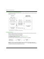
The technical characteristics of the devices described in this document also appear online. To
access this information online:
Step
Action
1
Go to the Schneider Electric home page www.schneider-electric.com.
2
In the Search box type the reference of a product or the name of a product range.
Do not include blank spaces in the model number/product range.
To get information on grouping similar modules, use asterisks (*).
3
If you entered a reference, go to the Product Datasheets search results and click on the
reference that interests you.
If you entered the name of a product range, go to the Product Ranges search results and click
on the product range that interests you.
4
If more than one reference appears in the Products search results, click on the reference that
interests you.
5
Depending on the size of your screen, you may need to scroll down to see the data sheet.
6
To save or print a data sheet as a .pdf file, click Download XXX product datasheet.
The characteristics that are presented in this manual should be the same as those characteristics
that appear online. In line with our policy of constant improvement, we may revise content over time
to improve clarity and accuracy. If you see a difference between the manual and online information,
use the online information as your reference.
35006188 10/2014
7
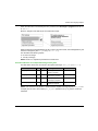
Related Documents
Title of Documentation
Reference Number
Modicon Modbus Plus Network, Planning and Installation Guide
31003525
Premium and Atrium using Unity Pro, Processors, racks and power
supply modules, Implementation manual
35010524 (English),
35010525 (French),
35006162 (German),
35012772 (Italian),
35006163 (Spanish),
35012773 (Chinese)
You can download these technical publications and other technical information from our website
at www.schneider-electric.com.
Product Related Information
WARNING
UNINTENDED EQUIPMENT OPERATION
The application of this product requires expertise in the design and programming of control
systems. Only persons with such expertise should be allowed to program, install, alter, and apply
this product.
Follow all local and national safety codes and standards.
Failure to follow these instructions can result in death, serious injury, or equipment
damage.
8
35006188 10/2014
Premium and Atrium Using Unity Pro
General
35006188 10/2014
Chapter 1
General
General
Aim of this Chapter
This chapter provides an overview of the main characteristics of a communication on Modbus Plus.
What Is in This Chapter?
This chapter contains the following topics:
Topic
Page
Introduction
10
Compatibility
11
Integration into an X-Way Architecture
12
Integration into a Modbus Plus Architecture
14
Peer Cop Service
15
Installation Phase Overview
18
35006188 10/2014
9
General
Introduction
Introduction
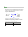
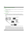
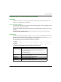
Modbus Plus communication is used to exchange data between all the devices connected on the
bus.
The Modbus Plus protocol is based on the principle of logical token passing. Each station of a
single network is identified by an address from 1 to 64, and each station accesses the network on
receiving a token. Duplicated addresses are not valid.
Example of network:
A Modbus Plus communication channel is made up of three main functions:
Point-to-point data exchanges via message system, using the Modbus protocol.
Global data broadcast exchanges between all of the stations taking part in the exchange.
Specific multidrop data exchanges via peer cop services.
Associated Manuals
For further information, you may consult the following manuals:
Title
Description
Modicon Modbus Plus Network, Planning and
Installation Guide (see page 8)
Detailed description of Modbus Plus
network implementation.
Hardware implementation for
Premium and Atrium using Unity Pro,
Processors, racks and power supply modules, Premium/Atrium processors.
Implementation manual
10
35006188 10/2014
General
Compatibility
Hardware
This type of communication is available for Premium and Atrium PLCs.
NOTE: Modbus Plus cards can only be used in slots located on the processors. It is impossible to
use SCY 21••• type modules.
Redundancy cannot be ensured on a Modbus network using Premium/Atrium PLCs.
Software
The Modbus Plus PCMCIA card TSX MBP 100 can process four communication functions
simultaneously.
The number of objects per communication function is from 1 to 125 words of useful read data and
from 1 to 120 words of useful write data (the maximum frame is 256 bytes).
For a communication from a Premium/Atrium PLC to a Quantum PLC, it is necessary to shift the
address settings. To access an address object n from a Quantum PLC, the communication
function on the Premium side must have the address n-1.
The Peer Cop service is supported only by Premium/Atrium PLCs.
When configuring the inputs and outputs for the Peer Cop service, it is possible to allocate up to
32 internal words for each connection point of the local bus. The total number of words must not
exceed 500 internal words.
35006188 10/2014
11
General
Integration into an X-Way Architecture
At a Glance
A Modbus Plus segment can be integrated into an X-Way network architecture.
Under certain operating conditions, communication is possible between stations on different
networks.
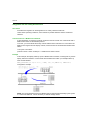
Communication to a Modbus Plus Network
A client application connected to a Fipway or Ethernet TCP/IP network can communicate with a
Modbus Plus station via the Modbus protocol.
To do this, you must indicate the X-Way network address of the Premium PLC connected to the
Modbus Plus segment and the Fipway network, and the number of the destination Modbus Plus
station.
The syntax is as follows:
{network number . station number}0. 0.1. Modbus Plus station number
Example
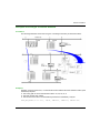
In this example, the Fipway station {5.3} has a Modbus Plus connection, meaning that any remote
Fipway station that wishes to communicate with a Modbus Plus station ( for example station 5)
must use this address.
READ_VAR(ADDR(’{5.3}0.0.1.5’), ’%MW’, 100, 10,%MW300:4, %MW200:10)
Configuration example
NOTE: The routing between Fipway and Modbus Plus is performed automatically by the system.
In a network architecture, it is not necessary to declare a bridge station.
12
35006188 10/2014
General
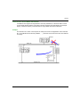
Communication from a Modbus Plus Network
If a Modbus Plus segment is integrated into an X-Way architecture, a Quantum station cannot
communicate with the stations connected on another network of the architecture (for example
Fipway or Ethernet TCP/IP). Communication is only possible with the local Premium.
Example
The Quantum PLC sends a write request to modify five words in the application of the Premium
PLC on the Modbus Plus network (%MW10, .....), but does not have access to the other stations
on Fipway.
35006188 10/2014
13
General
Integration into a Modbus Plus Architecture
At a Glance
In a Modbus Plus architecture, an application of a Quantum PLC can communicate with a Premium
or Atrium PLC or vice versa.
Premium to Quantum
Communication by a Premium/Atrium PLC to a remote station is described in the exchange service
on remote networks.
Quantum to Premium
Communication of a Quantum PLC to a Premium/Atrium PLC is available via MSTR blocks.
In this case, the Premium or Atrium PLCs are servers, meaning that all the Modbus Plus stations
connected in a network architecture, up to a maximum of five levels, can communicate with each
other.
Example
The Quantum station sends a read request to the Premium station using the following address
path: 8.5.1.0.0 (routing path).
The MSTR function block can be used to read or write internal words from a Premium or Atrium
station. The parameter of the MSTR function block’s slave register directly indicates the address
of the internal word %MW of the PLC application. This function block can also be used to read or
reset the statistic counters of a Premium or Micro station. This request is executed by the PCMCIA
card.
14
35006188 10/2014
General
Peer Cop Service
Introduction
The Peer Cop service is an automatic exchange mechanism between stations connected to the
same local Modbus Plus segment.
This service is used to maintain constant control over inputs / outputs which have been remoted
by implicit exchanges.
The Premium PLCs support two types of Peer Cop transfer:
specific inputs
specific outputs
Specific Inputs and Outputs
The specific inputs and outputs are point to point services which use the multicast protocol
(multistations). Each message contains one or several destination addresses for sending the data.
This function is used to exchange data to several stations without repetition.
Report
Three types of report are associated with the specific inputs and outputs:
activity bit: provides information on the availability and validity of the status bits
status bits (to the number of one bit per station):
ensure coherence between the number of specific inputs configured and the number of
specific inputs received
indicate if the specific inputs have been received during the Timeout
presence bits (to the number of one bit per station): indicate if the specific inputs have been
refreshed
NOTE: The presence bits are only valid for the specific inputs.
35006188 10/2014
15
General
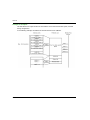
Example for the Inputs
The data blocks are copied in full from the PCMCIA card to the internal word space, reserved
during configuration.
In the following example, the address of the first internal word is %MW10.
16
35006188 10/2014
General
Example for the Outputs
The data blocks are copied in full from the internal word space, reserved during configuration, to
the PCMCIA card. The reports are copied from the PCMCIA card to the language objects.
In the following example, the address of the first internal word is %MW10.
35006188 10/2014
17
General
Installation Phase Overview
Introduction
The software installation of the application-specific modules is carried out from the various Unity
Pro editors:
in offline mode
in online mode
If you do not have a processor to connect to, Unity Pro allows you to carry out an initial test using
the simulator. In this case the installation (see page 19) is different.
The following order of installation phases is recommended but it is possible to change the order of
certain phases (for example, starting with the configuration phase).
Installation Phases with Processor
The following table shows the various phases of installation with the processor:
Phase
Description
Mode
Declaration of
variables
Declaration of IODDT-type variables for the applicationspecific modules and variables of the project.
Offline (1)
Programming
Project programming.
Offline (1)
Configuration
Declaration of modules.
Offline
Module channel configuration.
Entry of configuration parameters.
Association
Association of IODDTs with the channels configured
(variable editor).
Offline (1)
Generation
Project generation (analysis and editing of links).
Offline
Transfer
Transfer project to PLC.
Online
Adjustment/Debugging Project debugging from debug screens, animation tables.
Online
Modifying the program and adjustment parameters.
Documentation
Building documentation file and printing miscellaneous
information relating to the project.
Online (1)
Operation/Diagnostic
Displaying miscellaneous information necessary for
supervisory control of the project.
Online
Diagnostic of project and modules.
Key:
(1)
18
These various phases can also be performed in the other mode.
35006188 10/2014
General
Implementation Phases with Simulator
The following table shows the various phases of installation with the simulator.
Phase
Description
Mode
Declaration of variables
Declaration of IODDT-type variables for the applicationspecific modules and variables of the project.
Offline (1)
Programming
Project programming.
Offline (1)
Configuration
Declaration of modules.
Offline
Module channel configuration.
Entry of configuration parameters.
Association
Association of IODDTs with the modules configured
(variable editor).
Offline (1)
Generation
Project generation (analysis and editing of links).
Offline
Transfer
Transfer project to simulator.
Online
Simulation
Program simulation without inputs/outputs.
Online
Adjustment/Debugging
Project debugging from debug screens, animation tables.
Online
Modifying the program and adjustment parameters.
Key:
(1)
These various phases can also be performed in the other mode.
NOTE: The simulator is only used for the discrete or analog modules.
35006188 10/2014
19
General
20
35006188 10/2014
Premium and Atrium Using Unity Pro
PCMCIA TSX MBP 100 Card
35006188 10/2014
Chapter 2
Presentation of the PCMCIA TSX MBP 100 Card
Presentation of the PCMCIA TSX MBP 100 Card
35006188 10/2014
21
PCMCIA TSX MBP 100 Card
Section 2.1
Connection of the TSX MBP 100 Card
Connection of the TSX MBP 100 Card
Aim of this Section
This section deals with the hardware installation of TSX MBP 100 PCMCIA Modbus Plus cards.
What Is in This Section?
This section contains the following topics:
Topic
22
Page
Connecting the TSX MBP100 Card
23
General Principle for Connecting the PCMCIA Card
24
Grounding the TSX MBP CE 030/060 Cable
25
Connecting the TSX MBP CE 030/060 Cable to Modicon Connection Device 990 NAD 230 00
27
35006188 10/2014
PCMCIA TSX MBP 100 Card
Connecting the TSX MBP100 Card
General
The TSX MBP 100 PCMCIA card is connected to the Modbus Plus network using the
TSX MBP CE 030 branch cable, 3 m long, or the TSX MBP CE 060, 3 m long. This cable is
connected to Modicon branch device (local site tap) 990NA23000.
For information on how to install a Modbus Plus network, refer to the Modicon Modbus Plus
Network, Planning and Installation Guide (see page 8).
35006188 10/2014
23
PCMCIA TSX MBP 100 Card
General Principle for Connecting the PCMCIA Card
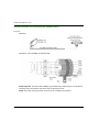
Principle
Illustration:
Description of the TSX MBP CE 030/060 cable:
NOTE: Important: The cable’s main shielding is grounded using a metal clamp in contact with the
screening braid, which itself is fixed to the frame supporting the rack.
NOTE: This cable must be grounded, even if there is no PCMCIA card present.
24
35006188 10/2014
PCMCIA TSX MBP 100 Card
Grounding the TSX MBP CE 030/060 Cable
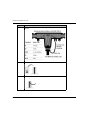
Procedure
The cable connecting the PCMCIA card to the Modicon branching device must be grounded as
shown below:
1
35006188 10/2014
Clip the loop clamp onto
the cable.
This loop clamp is
delivered with the
Modicon branching
device (Local Site Tap),
product reference 990
NAD 230 00.
25
PCMCIA TSX MBP 100 Card
2
26
Fix the clamp + cable unit
to the frame. The frame
itself is connected to the
ground.
35006188 10/2014
PCMCIA TSX MBP 100 Card
Connecting the TSX MBP CE 030/060 Cable to Modicon Connection Device 990
NAD 230 00
General
TSX MBP CE 030/060 cables are made up of two distinct sets of shielded twisted pair wires and
one external shielded ground wire, which makes a total of seven wires.
Connection Procedure
To connect the cable to the Modicon device follow the procedure below:
Step
1
Action
Identify the wires:
A first set of wires marked with the colors White and Orange, with one
stripped shielded wire.
A second set of wires marked with the colors White and Blue, with one
stripped shielded wire.
The external shielded wire
Note: It is important to correctly identify the two sets of twisted pairs since the
two white wires are not interchangeable
2
Set up the cable according to the dimensions given in the following illustration.
Illustration:
3
Insert the cable in the Modicon device and keep it in place using a clip.
35006188 10/2014
27
PCMCIA TSX MBP 100 Card
Step
28
Action
4
Connect the wires to the device, following the diagram below.
Diagram:
5
Remove the plastic hood from the terminal to connect each wire:
6
Place each wire in the corresponding terminal slot:
35006188 10/2014
PCMCIA TSX MBP 100 Card
Step
Action
7
Replace the hoods, and using a screwdriver press them to engage the wires in
their slots:
8
Finally, fix an open terminal to the external shielding wire either by soldering or
crimping, and connect it to the ground screw of the device as shown in stage 4
of the drawing.
35006188 10/2014
29
PCMCIA TSX MBP 100 Card
30
35006188 10/2014
Premium and Atrium Using Unity Pro
Software Installation
35006188 10/2014
Chapter 3
Software Installation
Software Installation
Aim of this Chapter
This chapter describes the different possibilities for configuring, supervising and diagnosing a
Modbus Plus station.
What Is in This Chapter?
This chapter contains the following sections:
Section
3.1
Topic
Page
Configuration
32
3.2
Programming
48
3.3
Debugging
59
35006188 10/2014
31
Software Installation
Section 3.1
Configuration
Configuration
Aim of this Section
This section describes the configuration of a PCMCIA card TSX MBP 100.
What Is in This Section?
This section contains the following topics:
Topic
32
Page
Method for Configuring a Modbus Plus Network
33
Modbus Plus Configuration Screen
41
Accessible Modbus Plus functions
43
Modbus Plus Configuration Parameters
44
Configuration of the Global data of the Peer Cop Utility
46
35006188 10/2014
Software Installation
Method for Configuring a Modbus Plus Network
At a Glance
The creation and configuration of a Modbus Plus network has four main steps:
creation of a Modbus Plus logic network
configuration of a Modbus Plus logic network
declaration of the Modbus Plus PCMCIA card
association of the card with the logic network
These four methods are presented in the remainder of this documentation.
NOTE: The advantage of this method is that from stage two onwards, you can devise your
communication application (you are not obliged to have the hardware to begin work) and use the
simulator to test its operation.
NOTE: The first two phases are run from the project browser and the next two from the hardware
configuration editor.
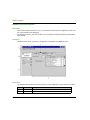
How to Create a Modbus Plus Logic Network
The following tables present the procedure for creating a Modbus Plus logic network.
Step
1
35006188 10/2014
Action
Right-click the Networks subdirectory of the Communication directory of the
Project browser and select the New network option.
Result:
33
Software Installation
Step
2
Action
Select Modbus Plus from the list of available networks and select a
meaningful name for it.
Result:
Note: If you click the Comments tab you can also enter a comment if you wish.
3
Click OK, and a new logic network is created.
Result: We have just created the Modbus Plus network which appears in the
project browser.
Note: As you can see, a small icon indicates that the logic network is not
associated with a PLC device.
34
35006188 10/2014
Software Installation
How to Access the Configuration of the Modbus Plus Logic Network
The following table presents the procedure for accessing the configuration of the Modbus Plus
logic network.
Step
1
Action
Open the project browser in order to see the logic networks of your application.
Result:
2
35006188 10/2014
Right-click the Modbus Plus logic network to be configured and select Open.
Result: The Modbus Plus configuration screen appears. This screen is described in the
remainder of this documentation
(see page 41).
35
Software Installation
How to Declare the Modbus Plus PCMCIA Card
The following table presents the procedure for physically declaring the Modbus Plus PCMCIA card
in the processor.
Step
36
Action
1
Open the hardware configuration editor.
2
Double click the PCMCIA communication card slot (bottom slot).
Result: The card type selection window appears.
3
Open up the Communication line by clicking the+ sign.
Result:
4
Select the Modbus Plus TSX MBP 100 card and then confirm with OK.
Result: The hardware configuration editor is displayed.
35006188 10/2014
Software Installation
Step
5
35006188 10/2014
Action
Double click the PCMCIA communication card of the processor.
Result:
37
Software Installation
Step
Action
6
Select the channel and choose the Modbus Plus function.
Result:
7
Confirm the modification and close the window.
Result: The Modbus Plus PCMCIA card is configured. All that remains now in
order for it to work is to associate it with a logic network.
Note: Confirmation is not mandatory, the modification is effective from step 6
onwards.
How to Associate the Logic Network
The following table presents the procedure for associating the Modbus Plus logic network to the
PCMCIA card that you have just declared.
Step
1
38
Action
Open the hardware configuration editor.
35006188 10/2014
Software Installation
Step
Action
2
Double click the PCMCIA card slot.
Result:
3
In the Function field select the network to be associated with the card.
Result:
35006188 10/2014
39
Software Installation
Step
4
40
Action
Confirm your choice and close the window.
Result: The Modbus Plus Atelier logical network is associated with the
TSX MBP 100 card. The address of the module is written in the logic network
configuration window. The icon associated with this logical network changes
and indicates the link with a PLC.
35006188 10/2014
Software Installation
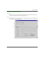
Modbus Plus Configuration Screen
Introduction
This screen is split into 5 zones that enable the declaration of the communication channel and
configuration of parameters necessary for a Modbus Plus link.
Figure
The figure below show a configuration screen for a PCMCIA TSX MBP 100 card accessible for the
communication tab of the project browser.
35006188 10/2014
41
Software Installation
Description
The following table presents the various elements of the configuration screen and their functions.
42
Address Element
Function
1
Address zone
The address zone is empty if the logic network has not been associated with the
hardware, it contains the address of the PCMCIA Modbus Plus card when the
association has been made (see page 38).
2
Configuration This zone allows configuration of the Modbus Plus link.
zone
It is broken down into two types of information:
the station address
the parameters of the Peer Cop utility
35006188 10/2014
Software Installation
Accessible Modbus Plus functions
Introduction
Depending on the communication media chosen, certain parameters cannot be modified. These
appear in gray.
Accessible Functions
The table below summarizes the various possible choices:
Functions
TSX MBP 100
Input fallback mode
Accessible if the Peer Cop checkbox is checked
Global inputs and outputs
This area is available only on Quantum PLCs.
Specific inputs and outputs
Accessible if the Peer Cop checkbox is checked (Premium
and Atrium PLCs)
35006188 10/2014
43
Software Installation
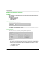
Modbus Plus Configuration Parameters
Introduction
After configuring the communication channel, you need to enter the parameters intended for the
Modbus Plus link.
These are split into two zones:
the Station number zone
the Peer Cop zone
Addressing Parameter
Illustration of the Station number zone:
This parameter allows the address (or connection point) of the station on the Modbus Plus network
to be defined; it is a number between 1 and 64.
Peer Cop Parameters
This window can only be accessed by checking the Peer Cop: checkbox
This allows you to:
44
enter the value of the Time Out: refresh time of inputs in milliseconds. This allows specification
of the maximum time for which the inputs coming from the remote stations must be updated in
the PCMCIA card. In the event that the data are not refreshed in the time stated, an error is
detected.
the default value is 500 ms,
values between 20 ms and 2 s,
the increment is 20 ms.
35006188 10/2014
Software Installation
enter the Input Fallback Mode:
maintained,
Reset to zero.
accessing the values of the specific inputs and specific outputs. Peer Cop Service, page 15
NOTE: The global inputs and outputs are not used on the Premium PLCs, they can be configured
on the Quantum PLCs.
35006188 10/2014
45
Software Installation
Configuration of the Global data of the Peer Cop Utility
Introduction
If you have checked the Peer Cop box, you must specify the starting address and the size of the
data to be exchanged.
These data are stored in the internal words of the application. Peer Cop Service, page 15
Configuration Rules
The input words field cannot superimpose on the output words field.
The internal words corresponding to the specific inputs or outputs are latched continuously.
The maximum size of the specific data must not exceed 1,000 words (500 words max. for the inputs
and 500 words max. for the outputs).
Specific Inputs
After selecting the Inputs button of the Specific zone, the following window appears.
For each connection point of the local bus segment, the user must define:
the starting address in the table of internal words (%MW)
the size of the exchanges, from 0 to 32 words per station, on the local bus segment
NOTE: The line of the local station (1 in this example) appears grayed out, it is not possible to
associate input words with it.
46
35006188 10/2014
Software Installation
Specific Outputs
After selecting the Specific outputs button, the following window appears.
For each connection point of the local bus segment, the user must define:
the starting address in the table of internal words (%MW)
the size of the exchanges, from 0 to 32 words per station, on the local bus segment
35006188 10/2014
47
Software Installation
Section 3.2
Programming
Programming
Aim of this Section
This section describes the tools available to program the operation of and to obtain information on
a Modbus Plus network managed by the TSX MBP 100 card.
What Is in This Section?
This section contains the following topics:
Topic
48
Page
Read and Write Service on a local Segment
49
Exchange Service on Remote Modbus Plus Networks
51
Examples of Exchanges on Remote Networks
53
Diagnostics Service
55
Global Data Exchange Service
57
35006188 10/2014
Software Installation
Read and Write Service on a local Segment
Introduction
A Premium or Atrium PLC can exchange data with stations connected on the local Modbus Plus
network.
Data Exchange
The READ_VAR and WRITE_VAR functions can be used to access bits, internal words or
input/output words on remote stations on a single local segment in read/write mode.
The address setting from a Premium station will be, for example:
in read
READ_VAR (ADDR(’0.0.1.10’), ’%MW’, 10, 20, %MW100:4, %MW10:20)
in write
WRITE_VAR (ADDR(‘0.0.1.10’), ‘%MW’, 10, 20, %MW10:20, %MW100:4)
The following table describes the different parameters of the function.
Parameter
Description
ADDR(‘0.0.1.10’)
Address of the destination device of the message:
0 : rack number (always 0 as the card is in the processor)
0 : processor slot: 0 or 1
1 : PCMCIA channel
10 : destination station number
‘%MW’
Type of object to read or write, for example: internal words
10
Address of the first word to read or write
20
Number of words to read or write
%MW10:20
When reading: content of the response
When writing: value of the words to be written
%MW100:4
Management table (see Unity Pro, Communication, Block Library),
containing:
the activity bit,
the operation report,
the communication report,
the time-out,
the number of bytes sent or received.
35006188 10/2014
49
Software Installation
Correspondence of the Types of Objects
The following tables describe the correspondence between types of objects between
Premium/Atrium and Quantum PLCs.
In the case where a Premium/Atrium PLC sends the request and a Quantum PLC receives it.
READ_VAR or WRITE_VAR
function
Premium/Atrium object
type
Responding Quantum object
‘%MW’
internal words
4x... memory area
‘%M’
Internal bits
0x... memory area
‘%IW’
input words
3x... memory area
‘%I’
input bits
1x... memory area
In the case where a Quantum PLC sends via a MSTR function block.
MSTR function block
Responding Premium/Atrium object
READ
%MW
WRITE
%MW
Example
The Premium application writes 10 internal words to the Quantum PLC (address 2) and reads 5
input words from the Quantum PLC (address 5).
The internal words to write to station 2 are located at address 10.
The input words to read from station 5 are located at address 5.
50
35006188 10/2014
Software Installation
Exchange Service on Remote Modbus Plus Networks
Introduction
A Premium or Atrium PLC can exchange data with stations connected on other Modbus Plus
segments, via BP85 Bridge Plus gateways.
Accessing a Remote Station
To access a remote station connected to another network segment, the full routing path must be
indicated in the information to be sent.
You must first indicate in the request the address of the first destination connection point on the
local bus.
You must then specify in the data to be sent each address of the devices which will enable
transmission to the destination station.
Data Exchange
This type of exchange is accessible using the SEND_REQ function. To differentiate between the
reading and writing of data from a remote station, a request code is associated with the SEND_REQ
function. These are explicit exchanges managed by the application.
The address setting from a Premium station will be, for example:
in read
SEND_REQ (ADDR(’0.0.1.61’), 16#36, %MW300:500, %MW600:4, %MW450:15)
in write
SEND_REQ (ADDR(’0.0.1.61’), 16#37, %MW300:50, %MW600:4, %MW450:150)
The following table describes the different parameters of the function.
Parameter
ADR#(‘0.0.1.61’)
Description
Address of the destination device of the message:
0 : rack number (always 0 as the card is in the processor)
0 : processor slot: 0 or 1
1 : PCMCIA channel
number of the destination connection point on the local bus: 61
16#36
16#37
Request code to read objects
Request code to write objects
%MW300:50
Address path, length, data to be transmitted
%MW600:4
Activity bit, exchange report, length
%MW450:150
Address, length of the data to be received
35006188 10/2014
51
Software Installation
Coding of Data
The read/write request data is coded in the internal words, to be sent as follows.
52
35006188 10/2014
Software Installation
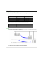
Examples of Exchanges on Remote Networks
At a Glance
The following illustration shows the two types of exchange which are processed as follows:
Example 1
Reading, using a Premium PLC, of 120 internal words at address 80 of the Quantum station (local
address 62) requires:
The routing path to access the Quantum station: 61, 30, 22, 62, 0.
The read request code: 16#36.
The real size of the data to be transmitted (memorized in %MW603): 10 bytes.
SEND_REQ(ADDR(’0.0.1.61’), 16#36, %MW300:5, %MW600:4, %MW450:120)
35006188 10/2014
53
Software Installation
Coding of the data to be transmitted:
Parameters
Values
Description
%MW300
0x161E
Second and third crossing point addresses (30, 22)
%MW301
0x003E
Fourth and fifth crossing point addresses (62, 0)
%MW302
0x0768
Segment 104 and type 7 (according to the type of variable to be read or written)
%MW303
80
Address of the first internal word to be read in the Quantum station
%MW304
120
Size of the data to be read (in number of bytes, the size of useful data is between
1 and 125 words in read mode)
No data
NOTE: After the execution of the SEND_REQ function, it is necessary to reclassify the bytes in the
correct order.
Example 2
Writing, using a Premium PLC, of 50 internal words at address 560 of slave 49 connected to port
4 of the multiplexer bridge requires:
The routing path to access the slave: 61, 25, 4, 49, 0.
The write request code: 16#37.
The real size of the data to be transmitted (memorized in %MW603): 110 bytes.
The values of the data to be written (memorized in %MW305 to %MW354).
The response (memorized in %MW450:1): does not contain any data to be received, but should
have a minimum length of one word.
SEND_REQ(ADDR(’0.0.1.61’), 16#37, %MW300:55, %MW600:4, %MW450:1)
Coding of the data to be transmitted:
Parameters
Values
Description
%MW300
0x0419
Second and third crossing point addresses (25, 4)
%MW301
0x0031
Fourth and fifth crossing point addresses (49, 0)
%MW302
0x0768
Segment 104 and type 7 (according to the type of variable to be read or written)
%MW303
560
Address of the first internal word to be written in the Quantum station
%MW304
50
Size of the data to be written (in number of bytes, the size of useful data is
between 1 and 120 words in write mode)
%MW305 to
%MW354
%MW603
54
Data to be written
110
Real size of the data to be transmitted with this function (in bytes)
35006188 10/2014
Software Installation
Diagnostics Service
Introduction
A Premium or Atrium PLC can read or reset to zero the local or remote error counters on a local
Modbus Plus network.
Data Exchange
This type of exchange is accessible using the SEND_REQ function. To differentiate between the
reading and writing of data from a remote station, a request code is associated with the SEND_REQ
function.
The address setting from a Premium station will be, for example:
to read the counters
SEND_REQ (ADDR(’0.0.1.5’), 16#A2, %MW100:1, %MW300:4, %MW200:20)
to reset the counters to zero
SEND_REQ (ADDR(’0.0.1.5’), 16#A4, %MW100:1, %MW300:4, %MW200:1)
The following table describes the different parameters of the function.
Parameter
ADDR(‘0.00.5.10’)
Description
Address of the destination device of the message:
0 : rack number (always 0 as the card is in the processor)
0 : processor slot: 0 or 1
1 : PCMCIA channel
5 : number of the destination connection point on the local bus
16#A2
16#A4
Request code to read the counters
Request code to reset the counters to zero
%MW100:1
No data to send
%MW200:20
%MW200:1
No response on reception
Content of the error counters
%MW300:4
Activity bit, exchange report, length
NOTE: The length parameter in the report words is initialized to 0 before the request is sent.
35006188 10/2014
55
Software Installation
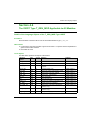
List of Counters
The following table shows all the counters.
Counter number
56
Meaning
1
Retransmit deferral error counter
2
Receive buffer DMA overrun error counter
3
Repeated command received counter
4
Frame size error counter
5
Receiver collision abort error counter
6
Receiver alignment error counter
7
Receiver CRC error counter
8
Bad-packet-length error counter
9
Bad link address error counter
10
Transmit buffer DMA underrun error counter
11
Bad internal packet length error counter
12
Bad mac function code error counter
13
Communication retry counter
14
Communication failed error counter
15
Good receive packet success counter
16
No response received error counter
17
Exception response received error counter
18
Unexpected path error counter
19
Unexpected response error counter
20
Forgotten transaction error counter
35006188 10/2014
Software Installation
Global Data Exchange Service
Introduction
The global data exchange service is a simple exchange mechanism used to send broadcast
messages between stations connected to the same Modbus Plus network.
During the course of an exchange, a station which has a token can broadcast words to other
stations connected to the network. A receiving station takes the content of the words sent by the
transmitting station, saves them to the PCMCIA card memory, then sends them back onto the
network. The same applies to each station which passes the token.
NOTE: The transfer of data from one station to another is performed automatically.
To read the transmitted global data, the application of the receiver station must read from its
PCMCIA card.
Precautions for Use
For Premium and Atrium PLCs, this service is provided by specific communication functions
(WRITE_GDATA and READ_GDATA), which carried out by the application periodically. It is not a
built-in feature of Peer Cop transactions.
A Premium or Atrium PLC can broadcast a maximum of 32 words.
Writing Global Data
This type of exchange is accessible using the WRITE_GDATA function.
The address setting from a Premium station will be, for example:
WRITE_GDATA (ADDR(‘0.0.1.SYS’), %MW100:x, %MW200:4)
The following table describes the different parameters of the function.
Parameter
Description
ADDR(‘0.0.1.SYS’)
Address for a broadcast:
0 : rack number (always 0 as the card is in the processor)
0 : processor slot: 0 or 1
1 : PCMCIA channel
system channel: transmission for all stations on the network
%MW100:x
Content of the global data to be sent (x = 1 to 32 words)
%MW200:4
Activity bit, exchange report, length
Reading Global Data
This type of exchange is accessible using the READ_GDATA function.
The address setting from a Premium station will be, for example:
READ_GDATA (ADDR(’0.0.1.10’), %MW300:4, %MW30:32)
35006188 10/2014
57
Software Installation
The following table describes the different parameters of the function.
Parameter
ADDR(‘0.0.1.10’)
Description
Address of the transmitting device of the message:
0 : rack number (always 0 as the card is in the processor)
0 : processor slot: 0 or 1
1 : PCMCIA channel
number of the station transmitting the data: 10
%MW300:4
Activity bit, exchange report, length
%MW30:32
Content of global data
NOTE: The length of the global data actually read is contained in the length word of the activity
report (e.g.: %MW304). When length = 0, this means there is no new global data available in the
station specified in the request.
58
35006188 10/2014
Software Installation
Section 3.3
Debugging
Debugging
Aim of this Section
This section describes the debugging of a TSX MBP 100 PCMCIA card.
What Is in This Section?
This section contains the following topics:
Topic
Page
Modbus Plus Debug Screen
60
Modbus Plus Debug Screen
62
35006188 10/2014
59
Software Installation
Modbus Plus Debug Screen
At a Glance
This screen is broken down into 5 zones, 3 zones that are identical to the configuration screen and
two zones specific to the debugging.
The Debug tab (zone 1) is a zone in which you can modify the debug parameters for the Modbus
Plus channel.
Illustration
The figure below shows a screen for configuration of a PCMCIA TSX MBP 100 card.
Description
The following table presents the various elements of the configuration screen and their functions.
60
Number
Element
Function
1
Tabs
The tab in the foreground indicates the current mode (Debug).
2
Module area
Contains the abbreviated title of the module.
35006188 10/2014
Software Installation
Number
Element
3
Channel area This zone indicates the channel on which the debugging is carried out.
In our case a single channel is available for the TSX MBP 100 card.
4
Global
Parameters
area
This zone allows the general parameters associated with the channel to
be chosen:
Function: for a TSX MBP 100 card a single function is available, the
Modbus Plus function
Task: defines the task (MAST or FAST or AUX0/1) in which the
channel’s explicit exchange objects will be exchanged
Net Link: defines the logic network with which the Modbus Plus card
is associated
5
Debug zone
This zone lets you debug the Modbus Plus link.
It is broken down into two types of information:
the station address
debug values
35006188 10/2014
Function
61
Software Installation
Modbus Plus Debug Screen
At a Glance
The three elements of the Modbus Plus debug zone are as follows:
the Station number zone
the Debug value zone
the Reset counters button
Station Number
The zone, identical to that in configuration, is used to select:
either the local station
or the remote station
Debug Values
The window looks like this:
This window displays the different fault counters of a station connected to the Modbus Plus
network.
By default, the screen proposes the default counters of the local station. It is possible to view the
fault counters of a local station or of a remote station.
NOTE: To access the fault counters of a remote station, you must first select the number of the
remote station.
Reset Counters
The Reset Counters button resets the default counters to zero.
62
35006188 10/2014
Premium and Atrium Using Unity Pro
Modbus Plus language objects
35006188 10/2014
Chapter 4
Modbus Plus Language Objects
Modbus Plus Language Objects
Aim of this Chapter
This chapter describes the language objects associated with the Modbus Plus communication
channel.
What Is in This Chapter?
This chapter contains the following sections:
Section
Topic
Page
4.1
Language Objects and IODDTs for Modbus Plus Communication
4.2
Language Objects and Generic IODDT Applicable to Communication Protocols
73
4.3
Language Objects of the IODDT Specific Modbus Plus
77
4.4
The IODDT Type T_GEN_MOD Applicable to All Modules
85
35006188 10/2014
64
63
Modbus Plus language objects
Section 4.1
Language Objects and IODDTs for Modbus Plus Communication
Language Objects and IODDTs for Modbus Plus
Communication
Aim of this Section
This section provides an overview of general points relating to Modbus Plus communication
language objects and IODDTs.
What Is in This Section?
This section contains the following topics:
Topic
64
Page
Introduction to Language Objects for Modbus Plus Communication
65
Implicit Exchange Language Objects Associated with the Application-Specific Function
66
Explicit Exchange Language Objects Associated with the Application-Specific Function
67
Management of Exchanges and Reports with Explicit Objects
69
35006188 10/2014
Modbus Plus language objects
Introduction to Language Objects for Modbus Plus Communication
General
The IODDTs are predefined by the manufacturer. They contain input/output language objects
belonging to a channel of an application-specific module.
Modbus Plus communication has two associated IODDTs:
T_COM_STS_GEN, which applies to communication protocols except Fipio and Ethernet,
T_COM_MBP, which is specific to Modbus Plus communication
NOTE: IODDT variables can be created in two different ways:
Using the I/O objects (see Unity Pro, Operating Modes) tab
Data Editor (see Unity Pro, Operating Modes)
Language Object Types
Each IODDT contains a group of language objects which are used to control them and check their
operation.
There are two types of language object:
implicit exchange objects, which are automatically exchanged on each cycle of the task
associated with the module
explicit exchange objects, which are exchanged on the application’s request, using explicit
exchange instructions
Implicit exchanges concern the status of the modules, the communication signals, the slaves, etc.
Explicit exchanges are used to set up the module’s parameters and for module diagnostics.
35006188 10/2014
65
Modbus Plus language objects
Implicit Exchange Language Objects Associated with the Application-Specific
Function
At a Glance
An integrated application-specific interface or the addition of a module automatically enhances the
language objects application used to program this interface or module.
These objects correspond to the input/output images and software data of the module or integrated
application-specific interface.
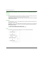
Reminders
The module inputs (%I and %IW) are updated in the PLC memory at the start of the task, the PLC
being in RUN or STOP mode.
The outputs (%Q and %QW) are updated at the end of the task, only when the PLC is in RUN mode.
NOTE: When the task occurs in STOP mode, either of the following are possible, depending on
the configuration selected:
outputs are set to fallback position (fallback mode)
outputs are maintained at their last value (maintain mode)
Figure
The following diagram shows the operating cycle of a PLC task (cyclical execution).
66
35006188 10/2014
Modbus Plus language objects
Explicit Exchange Language Objects Associated with the Application-Specific
Function
Introduction
Explicit exchanges are performed at the user program’s request using these instructions:
READ_STS (see Unity Pro, I/O Management, Block Library) (read status words)
WRITE_CMD (see Unity Pro, I/O Management, Block Library) (write command words)
WRITE_PARAM (see Unity Pro, I/O Management, Block Library) (write adjustment parameters)
READ_PARAM (see Unity Pro, I/O Management, Block Library) (read adjustment parameters)
SAVE_PARAM (see Unity Pro, I/O Management, Block Library) (save adjustment parameters)
RESTORE_PARAM (see Unity Pro, I/O Management, Block Library) (restore adjustment
parameters)
These exchanges apply to a set of %MW objects of the same type (status, commands or
parameters) that belong to a channel.
These objects can:
provide information about the module (for example, type of error detected in a channel)
have command control of the module (for example, switch command)
define the module’s operating modes (save and restore adjustment parameters in the process
of application)
NOTE: To avoid several simultaneous explicit exchanges for the same channel, it is necessary to
test the value of the word EXCH_STS (%MWr.m.c.0) of the IODDT associated to the channel
before calling any EF addressing this channel.
NOTE: Explicit Exchanges are not supported when Modicon M340 Analog and Digital I/O modules
are configured behind a M340 Ethernet Remote I/O adapter module in a Quantum EIO Ethernet
Configuration. As a consequence, it is not possible to setup a module’s parameters from the PLC
application during operation.
35006188 10/2014
67
Modbus Plus language objects
General Principle for Using Explicit Instructions
The diagram below shows the different types of explicit exchanges that can be made between the
application and module.
Managing Exchanges
During an explicit exchange, check performance to see that the data is only taken into account
when the exchange has been correctly executed.
To do this, two types of information is available:
information concerning the exchange in progress (see page 71)
the exchange report (see page 72)
The following diagram describes the management principle for an exchange.
NOTE: In order to avoid several simultaneous explicit exchanges for the same channel, it is
necessary to test the value of the word EXCH_STS (%MWr.m.c.0) of the IODDT associated to the
channel before calling any EF addressing this channel.
68
35006188 10/2014
Modbus Plus language objects
Management of Exchanges and Reports with Explicit Objects
At a Glance
When data is exchanged between the PLC memory and the module, the module may require
several task cycles to acknowledge this information. All IODDTs use two words to manage
exchanges:
EXCH_STS (%MWr.m.c.0): exchange in progress
EXCH_RPT (%MWr.m.c.1): report
NOTE:
Depending on the localization of the module, the management of the explicit exchanges
(%MW0.0.MOD.0.0 for example) will not be detected by the application:
For in-rack modules, explicit exchanges are done immediately on the local PLC Bus and are
finished before the end of the execution task. So, the READ_STS, for example, is always finished
when the %MW0.0.mod.0.0 bit is checked by the application.
For remote bus (Fipio for example), explicit exchanges are not synchronous with the execution
task, so the detection is possible by the application.
Illustration
The illustration below shows the different significant bits for managing exchanges:
35006188 10/2014
69
Modbus Plus language objects
Description of Significant Bits
Each bit of the words EXCH_STS (%MWr.m.c.0) and EXCH_RPT (%MWr.m.c.1) is associated with
a type of parameter:
Rank 0 bits are associated with the status parameters:
The STS_IN_PROGR bit (%MWr.m.c.0.0) indicates whether a read request for the status
words is in progress.
The STS_ERR bit (%MWr.m.c.1.0) specifies whether a read request for the status words is
accepted by the module channel.
Rank 1 bits are associated with the command parameters:
The CMD_IN_PROGR bit (%MWr.m.c.0.1) indicates whether command parameters are
being sent to the module channel.
The CMD_ERR bit (%MWr.m.c.1.1) specifies whether the command parameters are
accepted by the module channel.
Rank 2 bits are associated with the adjustment parameters:
The ADJ_IN_PROGR bit (%MWr.m.c.0.2) indicates whether the adjustment parameters are
being exchanged with the module channel (via WRITE_PARAM, READ_PARAM,
SAVE_PARAM, RESTORE_PARAM).
The ADJ_ERR bit (%MWr.m.c.1.2) specifies whether the adjustment parameters are
accepted by the module. If the exchange is correctly executed, the bit is set to 0.
Rank 15 bits indicate a reconfiguration on channel c of the module from the console
(modification of the configuration parameters + cold start-up of the channel).
The r, m and c bits indicates the following elements:
the r bit represents the rack number.
The m bit represents the position of the module in the rack.
The c bit represents the channel number in the module.
NOTE: r represents the rack number, m the position of the module in the rack, while c represents
the channel number in the module.
NOTE: Exchange and report words also exist at module level EXCH_STS (%MWr.m.MOD) and
EXCH_RPT (%MWr.m.MOD.1) as per IODDT type T_GEN_MOD.
Example
Phase 1: Sending data by using the WRITE_PARAM instruction
70
35006188 10/2014
Modbus Plus language objects
When the instruction is scanned by the PLC processor, the Exchange in progress bit is set to 1
in %MWr.m.c.
Phase 2: Analysis of the data by the I/O module and report.
When the data is exchanged between the PLC memory and the module, acknowledgement by the
module is managed by the ADJ_ERR bit (%MWr.m.c.1.2).
This bit makes the following reports:
0: correct exchange
1: faulty exchange)
NOTE: There is no adjustment parameter at module level.
Execution Indicators for an Explicit Exchange: EXCH_STS
The table below shows the control bits of the explicit exchanges: EXCH_STS (%MWr.m.c.0)
Standard symbol
Type
Access
Meaning
Address
STS_IN_PROGR
BOOL
R
Reading of channel status %MWr.m.c.0.0
words in progress
CMD_IN_PROGR
BOOL
R
Command parameters
exchange in progress
%MWr.m.c.0.1
ADJ_IN_PROGR
BOOL
R
Adjust parameters
exchange in progress
%MWr.m.c.0.2
RECONF_IN_PROGR
BOOL
R
Reconfiguration of the
module in progress
%MWr.m.c.0.15
NOTE: If the module is not present or is disconnected, explicit exchange objects (READ_STS for
example) are not sent to the module (STS_IN_PROG (%MWr.m.c.0.0) = 0), but the words are
refreshed.
35006188 10/2014
71
Modbus Plus language objects
Explicit Exchange Report: EXCH_RPT
The table below shows the report bits: EXCH_RPT (%MWr.m.c.1)
Standard symbol
Type
Access
Meaning
Address
STS_ERR
BOOL
R
Error reading channel status words %MWr.m.c.1.0
(1 = failure)
CMD_ERR
BOOL
R
Error during a command parameter %MWr.m.c.1.1
exchange
(1 = failure)
ADJ_ERR
BOOL
R
Error during an adjust parameter
exchange
(1 = failure)
%MWr.m.c.1.2
RECONF_ERR
BOOL
R
Error during reconfiguration of the
channel
(1 = failure)
%MWr.m.c.1.15
Counting Module Use
The following table describes the steps realised between a Couting Module and the system after
a power-on.
Step
Action
1
Power on.
2
The system sends the configuration parameters.
3
The system sends the adjust parameters by WRITE_PARAM method.
Note: When the operation is finished, the bit %MWr.m.c.0.2 switches to 0.
If, in the begining of your application, you use a WRITE_PARAM command, you must wait until the
bit %MWr.m.c.0.2 switches to 0.
72
35006188 10/2014
Modbus Plus language objects
Section 4.2
Language Objects and Generic IODDT Applicable to Communication Protocols
Language Objects and Generic IODDT Applicable to
Communication Protocols
About this Section
This section presents the language objects and generic IODDT applicable to all communication
protocols except Fipio and Ethernet.
What Is in This Section?
This section contains the following topics:
Topic
Page
Details of IODDT Implicit Exchange Objects of Type T_COM_STS_GEN
74
Details of IODDT Explicit Exchange Objects of Type T_COM_STS_GEN
75
35006188 10/2014
73
Modbus Plus language objects
Details of IODDT Implicit Exchange Objects of Type T_COM_STS_GEN
Introduction
The following table presents the IODDT implicit exchange objects of type T_COM_STS_GEN
applicable to all communication protocols except Fipio and Ethernet.
Error Bit
The table below presents the meaning of the detected error bit CH_ERROR (%Ir.m.c.ERR).
74
Standard Symbol
Type
Access
Meaning
Address
CH_ERROR
EBOOL
R
Communication channel error bit.
%Ir.m.c.ERR
35006188 10/2014
Modbus Plus language objects
Details of IODDT Explicit Exchange Objects of Type T_COM_STS_GEN
Introduction
This section presents the T_COM_STS_GEN type IODDT explicit exchange objects applicable to all
communication protocols except Fipio and Ethernet. It includes the word type objects whose bits
have a specific meaning. These objects are presented in detail below.
Sample Variable Declaration: IODDT_VAR1 of type T_COM_STS_GEN
Observations
In general, the meaning of the bits is given for bit status 1. In specific cases an explanation is
given for each status of the bit.
Not all bits are used.
Execution Flags of an Explicit Exchange: EXCH_STS
The table below shows the meaning of channel exchange control bits from channel EXCH_STS
(%MWr.m.c.0).
Standard Symbol Type
Access Meaning
Address
STS_IN_PROGR
R
%MWr.m.c.0.0
BOOL
Reading of channel status words in progress.
CMD_IN_PROGR
BOOL
R
Current parameter exchange in progress.
%MWr.m.c.0.1
ADJ_IN_PROGR
BOOL
R
Adjustment parameter exchange in progress.
%MWr.m.c.0.2
Explicit Exchange Report: EXCH_RPT
The table below presents the meaning of the exchange report bits EXCH_RPT (%MWr.m.c.1).
Standard Symbol Type
Access Meaning
Address
STS_ERR
R
Reading error for channel status words.
%MWr.m.c.1.0
BOOL
CMD_ERR
BOOL
R
Error during command parameter exchange.
%MWr.m.c.1.1
ADJ_ERR
BOOL
R
Error during adjustment parameter exchange.
%MWr.m.c.1.2
Standard Channel Faults, CH_FLT
The table below shows the meaning of the bits of the status word CH_FLT (%MWr.m.c.2). Reading
is performed by a READ_STS (IODDT_VAR1).
Standard Symbol
Type
Access Meaning
Address
NO_DEVICE
BOOL
R
No device is working on the channel.
%MWr.m.c.2.0
1_DEVICE_FLT
BOOL
R
A device on the channel is inoperative.
%MWr.m.c.2.1
BLK
BOOL
R
Terminal block not connected.
%MWr.m.c.2.2
TO_ERR
BOOL
R
Time out exceeded anomaly.
%MWr.m.c.2.3
35006188 10/2014
75
Modbus Plus language objects
Standard Symbol
76
Type
Access Meaning
Address
INTERNAL_FLT
BOOL
R
Internal detected error or channel self-testing.
%MWr.m.c.2.4
CONF_FLT
BOOL
R
Different hardware and software
configurations.
%MWr.m.c.2.5
COM_FLT
BOOL
R
Interruption of the communication with the PLC. %MWr.m.c.2.6
APPLI_FLT
BOOL
R
Application detected error (adjustment or
configuration).
%MWr.m.c.2.7
35006188 10/2014
Modbus Plus language objects
Section 4.3
Language Objects of the IODDT Specific Modbus Plus
Language Objects of the IODDT Specific Modbus Plus
Object of this Sub-chapter
This sub-chapter describes the implicit and explicit language objects of the IODDT specific Modbus
Plus, T_COM_MBP.
What Is in This Section?
This section contains the following topics:
Topic
Page
Details of the Implicit Exchange Objects of the IODDT of the T_COM_MBP Type
78
Details of the Explicit Exchange Objects of the IODDT of the T_COM_MBP Type
81
Language Objects Associated with Configuration
83
35006188 10/2014
77
Modbus Plus language objects
Details of the Implicit Exchange Objects of the IODDT of the T_COM_MBP Type
At a Glance
The tables below present the implicit exchange objects of the IODDT of the T_COM_MBP type that
are applicable to the Modbus Plus communication.
Error Bit
The following table shows the meaning of the error bit CH_ERROR (%I0.0.1.ERR).
Standard symbol
Type
Access
Meaning
Address
CH_ERROR
EBOOL
R
Communication channel error bit
%I0.0.1.ERR
Refresh Indicators
The following table presents the meanings of the word bits, the refresh indicators of the global data
of stations 1 to 64.
Standard symbol
Type
Access
Meaning
Address
STA_STS_1 to
STA_STS_16
BOOL
R
Presence of station 1 to 16 respectively when
exchanging data.
%IWr.m.c.2.0 to
%IWr.m.c.2.15
STA_STS_17 to
STA_STS_32
BOOL
R
Presence of station 17 to 32 respectively when
exchanging data.
%IWr.m.c.3.0 to
%IWr.m.c.3.15
STA_STS_33 to
STA_STS_48
BOOL
R
Presence of station 33 to 48 respectively when
exchanging data.
%IWr.m.c.4.0 to
%IWr.m.c.4.15
STA_STS_49 to
STA_STS_64
BOOL
R
Presence of station 49 to 64 respectively when
exchanging data.
%IWr.m.c.5.0 to
%IWr.m.c.5.15
NOTE: When set to 1, the bit from rank i indicates that the station’s global data is operational. The
station is participating in the token exchange.
NOTE: where i = 0 to 15 of word
%IWr.m.c.2.i for stations 1 to 16
%IWr.m.c.3.i for stations 17 to 32
%IWr.m.c.4.i for stations 33 to 48
%IWr.m.c.5.i for stations 49 to 64
NOTE: If station i is disconnected, the bit from rank i is reset to 0 only after the global data has
been read by the appplication using the EF "Read_Gdata" on this station or by a STOP/RUN from
PLC.
NOTE: The use of STA_STS_i to test the presence of station i on Modbus + is possible only if
EF Read_Gdata has been executed in the current cycle.
78
35006188 10/2014
Modbus Plus language objects
Indicators of Availability and Presence of Specific Inputs
The table below presents the indicators of availability and presence of specific inputs of stations
on the network.
Standard symbol
Type
Access
Meaning
Address
STS_IN_STAT_1_8
BOOL
R
Byte 0: the specific inputs of all remote stations are
available
Bit 0 = 0 : the specific inputs are not available
Bit 0 = 1 : the specific inputs are available
Bits 1 to 7 : reserved
%IWr.m.c.6
Byte 1: a bit at 1 indicates the presence of a station
that is transmitting specific inputs. Stations 1 to 8.
IN_STAT_9_24
BOOL
R
A bit at 1 indicates the presence of a station that is
transmitting specific inputs. Stations 9 to 24.
%IWr.m.c.7
IN_STAT_25_40
BOOL
R
A bit at 1 indicates the presence of a station that is
transmitting specific inputs. Stations 25 to 40.
%IWr.m.c.8
IN_STAT_41_56
BOOL
R
A bit at 1 indicates the presence of a station that is
transmitting specific inputs. Stations 41 to 56.
%IWr.m.c.9
IN_ST57_64_PRES1_8
BOOL
R
Byte 0: a bit at 1 indicates the presence of a station %IWr.m.c.10
that is transmitting specific inputs. Stations 57 to 64.
Byte 1: a bit at 1 indicates the presence of new
specific inputs. Stations 1 to 8.
IN_PRES_9_24
BOOL
R
A bit at 1 indicates the presence of new specific
inputs. Stations 9 to 24.
%IWr.m.c.11
IN_PRES_25_40
BOOL
R
A bit at 1 indicates the presence of new specific
inputs. Stations 25 to 40.
%IWr.m.c.12
IN_PRES_41_56
BOOL
R
A bit at 1 indicates the presence of new specific
inputs. Stations 41 to 56.
%IWr.m.c.13
IN_PRES_57_64
BOOL
R
A bit at 1 indicates the presence of new specific
inputs. Stations 57 to 64.
%IWr.m.c.14
Indicators of Availability and Presence of Specific Inputs
The table below presents the indicators of availability and presence of specific inputs of stations
on the network.
Standard symbol
Type
Access
Meaning
Address
STS_OUT_STAT_1_8
BOOL
R
Byte 0: the specific outputs of all remote stations are %IWr.m.c.15
available
Bit 0 = 0 : the specific inputs are not available
Bit 0 = 1 : the specific inputs are available
Bits 1 to 7 : reserved
Byte 1: a bit at 1 indicates the presence of a station
that is receiving specific outputs. Stations 1 to 8.
35006188 10/2014
79
Modbus Plus language objects
Standard symbol
Type
Access
Meaning
Address
OUTP_STAT_9_24
BOOL
R
A bit at 1 indicates the presence of a station that is
receiving specific outputs. Stations 9 to 24.
%IWr.m.c.16
OUTP_STAT_25_40
BOOL
R
A bit at 1 indicates the presence of a station that is
receiving specific outputs. Stations 25 to 40.
%IWr.m.c.17
OUTP_STAT_41_56
BOOL
R
A bit at 1 indicates the presence of a station that is
receiving specific outputs. Stations 41 to 56.
%IWr.m.c.18
OUTP_STAT_41_56
BOOL
R
A bit at 1 indicates the presence of a station that is
receiving specific outputs. Stations 57 to 64.
%IWr.m.c.19
80
35006188 10/2014
Modbus Plus language objects
Details of the Explicit Exchange Objects of the IODDT of the T_COM_MBP Type
At a Glance
This part presents the explicit exchange objects of the IODDT of the T_COM_MBP type that are
applicable to the Modbus Plus communication. This groups together word type objects, the bits of
which have a particular meaning. These objects are described in detail below.
Example of declaring a variable: IODDT_VAR1 of type T_COM_MBP
Notes
Generally speaking, the meaning of the bits is given for state 1 of this bit. In specific cases an
explanation is given for each status of the bit.
Not all bits are used.
Explicit Exchange Execution Indicator: EXCH_STS
The following table presents the meanings of the exchange control bits of the channel EXCH_STS
(%MWr.m.c.0).
Standard symbol Type
Access
Meaning
Address
STS_IN_PROGR
BOOL
R
Reading of the status words of the current
channel.
%MWr.m.0.0
CMD_IN_PROGR
BOOL
R
Command parameters exchange in progress.
%MWr.m.c.0.1
ADJ_IN_PROGR
BOOL
R
Command parameters adjustment in progress. %MWr.m.c.0.2
Explicit Exchange Report: EXCH_RPT
The table below presents the meanings of the report bitsEXCH_RPT (%MWr.m.c.1).
Standard symbol Type
Access
Meaning
Address
STS_ERR
BOOL
R
Channel status words reading error.
%MWr.m.c.1.0
CMD_ERR
BOOL
R
Fault during a command parameters exchange.
%MWr.m.c.1.1
ADJ_ERR
BOOL
R
Fault during an adjustment parameters
exchange.
%MWr.m.c.1.2
35006188 10/2014
81
Modbus Plus language objects
Standard Channel Faults, CH_FLT
The following table presents the meanings of the bits of the CH_FLT status word (%MWr.m.c.2).
The reading is performed by a READ_STS (IODDT_VAR1).
Standard symbol Type
NO_DEVICE
82
Access
BOOL R
Meaning
Address
No device is working on the channel.
%MWr.m.c.2.0
1_DEVICE_FLT
BOOL R
A device on the channel is faulty.
%MWr.m.c.2.1
BLK
BOOL R
Terminal strip error (not connected).
%MWr.m.c.2.2
TO_ERR
BOOL R
Timeout error (faulty wiring).
%MWr.m.c.2.3
INTERNAL_FLT
BOOL R
Internal fault or channel self-test.
%MWr.m.c.2.4
CONF_FLT
BOOL R
Different hardware and software configurations.
%MWr.m.c.2.5
COM_FLT
BOOL R
Problem communicating with the PLC.
%MWr.m.c.2.6
APPLI_FLT
BOOL R
Application fault (adjustment or configuration
fault).
%MWr.m.c.2.7
35006188 10/2014
Modbus Plus language objects
Language Objects Associated with Configuration
At a Glance
This page describes all configuration language objects enabling Modbus Plus communication
which can be displayed by the application program. These objects do not belong to the IODDT’s
of the channel.
Internal Constants
The following table describes the internal constants:
Object
Type
Access
Meaning
%KWr.m.c.0
INT
R
Type of channel: Byte 0 =38 for the Modbus Plus
communication
%KWr.m.c.1
INT
R
Byte 0: station address
%KWr.m.c.2
INT
R
Activation of the Peer Cop utility:
Byte 0 = 1: no Peer Cop utility
Byte 0 = 2: Peer Cop utility)
R
Behavior of Timeout
Byte 1 = 1: inputs reset to zero
Byte 1 = 2: inputs maintained at last value
R
Address of the first internal word %MW used for the
reception of specific inputs
%KWr.m.c.3
INT
%KWr.m.c.4
INT
%KWr.m.c.5
INT
R
Number of specific output words to be sent to
connection point 1 and 2
byte 0: connection point 1
byte 1: connection point 2
%KWr.m.c.6
INT
R
Number of specific output words to be sent to
connection point 3 and 4
byte 0: connection point 3
byte 1: connection point 4
%KWr.m.c.36 INT
R
Number of specific output words to be sent to
connection point 63 and 64
byte 0: connection point 63
byte 1: connection point 64
%KWr.m.c.37 INT
R
Number of specific input words to be received at
connection point 1 and 2
byte 0: connection point 1
byte 1: connection point 2
Address of the first internal word %MW used for the
sending of specific outputs
...
35006188 10/2014
...
83
Modbus Plus language objects
Object
Type
%KWr.m.c.38 INT
Access
Meaning
R
Number of specific input words to be received at
connection point 3 and 4
byte 0: connection point 3
byte 1: connection point 4
...
...
%KWr.m.c.36 INT
R
%KWr.m.c.69 INT
R
Number of specific input words to be received at
connection point 63 and 64
byte 0: connection point 63
byte 1: connection point 64
Time interval of the Timeout of the Peer Cop utility
be 0 = 1 to 100: from 20 ms to 2 s
84
35006188 10/2014
Modbus Plus language objects
Section 4.4
The IODDT Type T_GEN_MOD Applicable to All Modules
The IODDT Type T_GEN_MOD Applicable to All Modules
Details of the Language Objects of the T_GEN_MOD-Type IODDT
At a Glance
All the modules of Premium PLCs have an associated IODDT of type T_GEN_MOD.
Observations
In general, the meaning of the bits is given for bit status 1. In specific cases an explanation is
given for each status of the bit.
Not all bits are used.
List of Objects
The table below presents the objects of the IODDT:
Standard
symbol
Type
Access
Meaning
Address
MOD_ERROR
BOOL
R
Module error bit
%Ir.m.MOD.ERR
EXCH_STS
INT
R
Module exchange control word.
%MWr.m.MOD.0
STS_IN_PROGR
BOOL
R
Reading of status words of the module in
progress.
%MWr.m.MOD.0.0
EXCH_RPT
INT
R
Exchange report word.
%MWr.m.MOD.1
STS_ERR
BOOL
R
Fault when reading module status words.
%MWr.m.MOD.1.0
MOD_FLT
INT
R
Internal error word of the module.
%MWr.m.MOD.2
MOD_FAIL
BOOL
R
Internal error, module failure.
%MWr.m.MOD.2.0
CH_FLT
BOOL
R
Faulty channel(s).
%MWr.m.MOD.2.1
BLK
BOOL
R
Terminal block fault.
%MWr.m.MOD.2.2
CONF_FLT
BOOL
R
Hardware or software configuration fault.
%MWr.m.MOD.2.5
NO_MOD
BOOL
R
Module missing or inoperative.
%MWr.m.MOD.2.6
EXT_MOD_FLT
BOOL
R
Internal error word of the module (Fipio
extension only).
%MWr.m.MOD.2.7
MOD_FAIL_EXT
BOOL
R
Internal fault, module unserviceable (Fipio
extension only).
%MWr.m.MOD.2.8
CH_FLT_EXT
BOOL
R
Faulty channel(s) (Fipio extension only).
%MWr.m.MOD.2.9
35006188 10/2014
85
Modbus Plus language objects
Standard
symbol
86
Type
Access
Meaning
Address
BLK_EXT
BOOL
R
Terminal block fault (Fipio extension only).
%MWr.m.MOD.2.10
CONF_FLT_EXT
BOOL
R
Hardware or software configuration fault
(Fipio extension only).
%MWr.m.MOD.2.13
NO_MOD_EXT
BOOL
R
Module missing or inoperative (Fipio
extension only).
%MWr.m.MOD.2.14
35006188 10/2014
Premium and Atrium Using Unity Pro
Index
35006188 10/2014
Index
C
W
channel data structure for all modules
IODDT, 73
T_GEN_MOD, 85
channel data structure for communication
protocols
T_COM_MBP, 64
configuring, 32, 35
connecting, 22
WRITE_GDATA, 57
WRITE_VAR, 49
D
debugging, 59, 60
M
Modbus Plus, 9, 10
X-Way architectures, 12
P
parameter settings, 64
Peer Cop, 15
programming, 48
R
READ_GDATA, 57
READ_VAR, 49
S
SEND_REQ, 51
T
T_COM_MBP, 77, 81
T_COM_STS_GEN, 65
T_GEN_MOD, 85
TSXMBP100, 21
35006188 10/2014
87
Index
88
35006188 10/2014