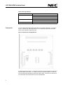
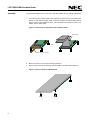
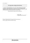
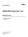
1
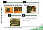
LCE-789014-EM Emulation Board for LCE-K0S Development System User’s Manual Introduction March 2000 The LCE-789014-EM is an emulation board or daughterboard for the LCE-K0S development system for NEC’s 8-bit µPD789014 subseries microcontrollers. Combining this board with the LCE-78K0S allows you to efficiently emulate any µPD789014 subseries device. The LCE789014-EM is shipped with the following contents: LCE-789014-EM daughterboard This manual One 50-pin ribbon cable CD-ROM containing debugger, compiler, assembler, and documentation Figure 1. System Configuration ID78K0S-LCE Debugger and Device File DF78K0S Host PC with Windows 95/98/NT Straight-Through Parallel Cable (sold separately) Power adapter (sold separately) Motherboard LCE-78K0S (sold separately) Daughterboard LCE-789014-EM Ribbon Cable Probe NP-28GT or NP-28CT (sold separately) Conversion Socket for Probe Only (sold separately) 50899-1 1 LCE-789014-EM Emulation Board Table 1. Basic Specification Parameter Description Target device µPD789011 µPD789012 µPD78P9014 Clock supply Internal: installed on the motherboard External: pulse input via an emulation probe from the target system Low-voltage compatible Components At least 2 volts The LCE-789014-EM daughterboard mates with the LCE-78K0S motherboard. As shown in Figure 2, a bottom view of the daughterboard, U1 is the Realchip that provides peripherals unique to the µPD789014 subseries devices. Figure 2. Bottom View of Daughterboard In thetop view shown in Figure 3, J1 and P1are connectors to the user target that contain all of the pins available on the device. J1 is a KEL connector for the probe, while P1 is a dual-row, male-shrouded header with latching levers for the ribbon cable. P3 and P4 are connectors for the motherboard, which attaches to the top of the daughterboard. 2 LCE-789014-EM Emulation Board Figure 3. Top View of Daughterboard Ribbon Cable The ribbon cable is a 50-pin female-to-female cable that connects the LCE-K0S to the user target. Alternatively, an emulation probe may be used. One end of the ribbon cable connects to the daughterboard and the other to the target. The side of the ribbon cable with a red stripe is pin 1. Table 2. P1 Pin Assignments P1 Connector µPD78901x Device Pin Signal Note 1 GND on probe cable 2 GND on probe cable 3 GND on probe cable 4 GND on probe cable 5 GND on probe cable 6 GND on probe cable 7 GND on probe cable 8 GND on probe cable 9 GND on probe cable 10 GND on probe cable 11 1 P31/INTP1/TI1/TO1 12 2 P32/INTP2 3 LCE-789014-EM Emulation Board Table 2. P1 Pin Assignments (continued) 4 P1 Connector µPD78901x Device Pin Signal 13 3 VPP 14 4 RESET 15 5 X2 16 6 X1 17 7 VSS 18 8 VDD 19 9 P00 20 10 P01 21 11 P02 22 12 P03 23 13 P04 24 14 P05 25 15 P06 26 16 P07 27 17 P10 28 18 P11 29 19 P12 30 20 P13 31 21 P14 32 22 P15 33 23 P16 34 24 P17 35 25 P20/ASCK/SCK0 36 26 P21/TXD/SO0 37 27 P22/RXD/SI0 38 28 P30/INTP0/TI0/TO0 Note 39 GND on probe cable 40 GND on probe cable 41 GND on probe cable 42 GND on probe cable 43 GND on probe cable 44 GND on probe cable 45 GND on probe cable 46 GND on probe cable 47 GND on probe cable 48 GND on probe cable 49 GND on probe cable 50 GND on probe cable LCE-789014-EM Emulation Board Emulation Probe (Optional) In place of ribbon cables, an emulation probe can be used to connect the LCE to the user target, provided the user target has a conversion socket/adapter installed. Table 3. Emulation Probe Pin Assignments Emulation Device Pin No. J1 Pin No. Emulation Device Pin No. J1 Pin No. 1 70 15 21 2 69 16 22 3 72 17 18 4 102 18 19 5 71 19 55 6 104 20 49 7 103 21 56 8 27 22 23 9 61 23 24 10 62 24 29 11 65 25 30 12 66 26 93 13 92 27 94 14 91 28 99 Table 4. Emulation Probe and Socket for µPD789014 Subseries Target Device Emulation Probe + Conversion Socket/Adapter µPD789011GT NP-28GT + 28GT-IC DUMMYSET µPD789012GT µPD78P9014GT µPD789011CT NP-28CT + generic DIP socket µPD789012CT µPD78P9014CT 5 LCE-789014-EM Emulation Board Assembly This procedure explains how to connect the LCE-789014-EM to the LCE-78K0S motherboard. 1. Connect the probe or ribbon cable to their respective connectors on the LCE-789014-EM (Figure 4). Note that the number of KEL connectors, headers, and ribbon cables shown in Figure 4 varies for each emulation board. The LCE-789014 has one KEL connector, one header, and one ribbon cable. Figure 4. Connections for Emulation Probe or Ribbon Cables Ribbon Cables OR Emulation Probe (sold separately) 2. Make sure power is off from the LCE-K0S motherboard. 3. Remove the two screws at the bottom of the standoffs on the motherboard (Figure 5). Figure 5. Screws on Bottom of Motherboard 6 LCE-789014-EM Emulation Board 4. With the daughterboard on a stable surface, connect the motherboard on the daughterboard by gently applying pressure on the mating connectors. Avoid applying pressure on the plastic cover (Figure 6). Figure 6. Daughterboard Mating Connectors A pply P ress ure o n th e M othe rbo ard 5. Replace the screws on the bottom of the daughterboard to securely connect it to the motherboard (Figure 7). Figure 7. Connection to Motherboard 6. Connect the loose end of the probe or ribbon cable to the user target. Refer to Table 2 and Table 3 for pin assignments. 7 7. With a 25-pin male-to-male parallel cable (not included), connect the LCE-K0S system to the host computer (Figure 8). Figure 8. Connection to Host PC Rear Side of the Motherboard Host PC Printer Port Straight-Through Parallel Cable 8. With the power adapter connected, turn the switch to the ON position. The green LED turns on when power is supplied to the system. 9. Launch the debugger from your PC. For literature, call 1-800-366-9782 7 a.m. to 6 p.m. Pacific time or FAX your request to 1-800-729-9288 or visit our web site at www.necel.com In North America: No part of this document may be copied or reproduced in any form or by any means without the prior written consent of NEC Electronics Inc. (NECEL). The information in this document is subject to change without notice. All devices sold by NECEL are covered by the provisions appearing in NECEL Terms and Conditions of Sales only. Including the limitation of liability, warranty, and patent provisions. NECEL makes no warranty, express, statutory, implied or by description, regarding information set forth herein or regarding the freedom of the described devices from patent infringement. NECEL assumes no responsibility for any errors that may appear in this document. NECEL makes no commitments to update or to keep current information contained in this document. The devices listed in this document are not suitable for use in applications such as, but not limited to, aircraft control systems, aerospace equipment, submarine cables, nuclear reactor control systems, and life support systems. “Standard” quality grade devices are recommended for computers, office equipment, communication equipment, test and measurement equipment, machine tools, industrial robots, audio and visual equipment, and other consumer products. For automotive and transportation equipment, traffic control systems, anti-disaster and anti-crime systems, it is recommended that the customer contact the responsible NECEL salesperson to determine the reliability requirements for any such application and any cost adder. NECEL does not recommend or approve use of any of its products in life support devices or systems or in any application where failure could result in injury or death. If customers wish to use NECEL devices in applications not intended by NECEL, customer must contact the responsible NECEL salespeople to determine NECEL's willingness to support a given application. ©2000 NEC Electronics Inc./Printed in U.S.A. 50899-1 For literature, call 1-800-366-9782 7 a.m. to 6 p.m. Pacific time or FAX your request to 1-800-729-9288 or visit our web site at www.necel.com In North America: No part of this document may be copied or reproduced in any form or by any means without the prior written consent of NEC Electronics Inc. (NECEL). The information in this document is subject to change without notice. All devices sold by NECEL are covered by the provisions appearing in NECEL Terms and Conditions of Sales only. Including the limitation of liability, warranty, and patent provisions. NECEL makes no warranty, express, statutory, implied or by description, regarding information set forth herein or regarding the freedom of the described devices from patent infringement. NECEL assumes no responsibility for any errors that may appear in this document. NECEL makes no commitments to update or to keep current information contained in this document. The devices listed in this document are not suitable for use in applications such as, but not limited to, aircraft control systems, aerospace equipment, submarine cables, nuclear reactor control systems, and life support systems. “Standard” quality grade devices are recommended for computers, office equipment, communication equipment, test and measurement equipment, machine tools, industrial robots, audio and visual equipment, and other consumer products. For automotive and transportation equipment, traffic control systems, anti-disaster and anti-crime systems, it is recommended that the customer contact the responsible NECEL salesperson to determine the reliability requirements for any such application and any cost adder. NECEL does not recommend or approve use of any of its products in life support devices or systems or in any application where failure could result in injury or death. If customers wish to use NECEL devices in applications not intended by NECEL, customer must contact the responsible NECEL salespeople to determine NECEL's willingness to support a given application. ©2000 NEC Electronics Inc./Printed in U.S.A. 50899-1 For literature, call 1-800-366-9782 7 a.m. to 6 p.m. Pacific time or FAX your request to 1-800-729-9288 or visit our web site at www.necel.com In North America: No part of this document may be copied or reproduced in any form or by any means without the prior written consent of NEC Electronics Inc. (NECEL). The information in this document is subject to change without notice. All devices sold by NECEL are covered by the provisions appearing in NECEL Terms and Conditions of Sales only. Including the limitation of liability, warranty, and patent provisions. NECEL makes no warranty, express, statutory, implied or by description, regarding information set forth herein or regarding the freedom of the described devices from patent infringement. NECEL assumes no responsibility for any errors that may appear in this document. NECEL makes no commitments to update or to keep current information contained in this document. The devices listed in this document are not suitable for use in applications such as, but not limited to, aircraft control systems, aerospace equipment, submarine cables, nuclear reactor control systems, and life support systems. “Standard” quality grade devices are recommended for computers, office equipment, communication equipment, test and measurement equipment, machine tools, industrial robots, audio and visual equipment, and other consumer products. For automotive and transportation equipment, traffic control systems, anti-disaster and anti-crime systems, it is recommended that the customer contact the responsible NECEL salesperson to determine the reliability requirements for any such application and any cost adder. NECEL does not recommend or approve use of any of its products in life support devices or systems or in any application where failure could result in injury or death. If customers wish to use NECEL devices in applications not intended by NECEL, customer must contact the responsible NECEL salespeople to determine NECEL's willingness to support a given application. ©2000 NEC Electronics Inc./Printed in U.S.A. 50899-1