1
To our customers,
Old Company Name in Catalogs and Other Documents
On April 1st, 2010, NEC Electronics Corporation merged with Renesas Technology
Corporation, and Renesas Electronics Corporation took over all the business of both
companies. Therefore, although the old company name remains in this document, it is a valid
Renesas Electronics document. We appreciate your understanding.
Renesas Electronics website: http://www.renesas.com
April 1st, 2010
Renesas Electronics Corporation
Issued by: Renesas Electronics Corporation (http://www.renesas.com)
Send any inquiries to http://www.renesas.com/inquiry.
Note that the following URLs in this document are not available:
http://www.necel.com/
http://www2.renesas.com/
Please refer to the following instead:
Development Tools | http://www.renesas.com/tools
Download | http://www.renesas.com/tool_download
For any inquiries or feedback, please contact your region.
http://www.renesas.com/inquiry
Notice
1.
2.
3.
4.
5.
6.
7.
All information included in this document is current as of the date this document is issued. Such information, however, is
subject to change without any prior notice. Before purchasing or using any Renesas Electronics products listed herein, please
confirm the latest product information with a Renesas Electronics sales office. Also, please pay regular and careful attention to
additional and different information to be disclosed by Renesas Electronics such as that disclosed through our website.
Renesas Electronics does not assume any liability for infringement of patents, copyrights, or other intellectual property rights
of third parties by or arising from the use of Renesas Electronics products or technical information described in this document.
No license, express, implied or otherwise, is granted hereby under any patents, copyrights or other intellectual property rights
of Renesas Electronics or others.
You should not alter, modify, copy, or otherwise misappropriate any Renesas Electronics product, whether in whole or in part.
Descriptions of circuits, software and other related information in this document are provided only to illustrate the operation of
semiconductor products and application examples. You are fully responsible for the incorporation of these circuits, software,
and information in the design of your equipment. Renesas Electronics assumes no responsibility for any losses incurred by
you or third parties arising from the use of these circuits, software, or information.
When exporting the products or technology described in this document, you should comply with the applicable export control
laws and regulations and follow the procedures required by such laws and regulations. You should not use Renesas
Electronics products or the technology described in this document for any purpose relating to military applications or use by
the military, including but not limited to the development of weapons of mass destruction. Renesas Electronics products and
technology may not be used for or incorporated into any products or systems whose manufacture, use, or sale is prohibited
under any applicable domestic or foreign laws or regulations.
Renesas Electronics has used reasonable care in preparing the information included in this document, but Renesas Electronics
does not warrant that such information is error free. Renesas Electronics assumes no liability whatsoever for any damages
incurred by you resulting from errors in or omissions from the information included herein.
Renesas Electronics products are classified according to the following three quality grades: “Standard”, “High Quality”, and
“Specific”. The recommended applications for each Renesas Electronics product depends on the product’s quality grade, as
indicated below. You must check the quality grade of each Renesas Electronics product before using it in a particular
application. You may not use any Renesas Electronics product for any application categorized as “Specific” without the prior
written consent of Renesas Electronics. Further, you may not use any Renesas Electronics product for any application for
which it is not intended without the prior written consent of Renesas Electronics. Renesas Electronics shall not be in any way
liable for any damages or losses incurred by you or third parties arising from the use of any Renesas Electronics product for an
application categorized as “Specific” or for which the product is not intended where you have failed to obtain the prior written
consent of Renesas Electronics. The quality grade of each Renesas Electronics product is “Standard” unless otherwise
expressly specified in a Renesas Electronics data sheets or data books, etc.
“Standard”:
8.
9.
10.
11.
12.
Computers; office equipment; communications equipment; test and measurement equipment; audio and visual
equipment; home electronic appliances; machine tools; personal electronic equipment; and industrial robots.
“High Quality”: Transportation equipment (automobiles, trains, ships, etc.); traffic control systems; anti-disaster systems; anticrime systems; safety equipment; and medical equipment not specifically designed for life support.
“Specific”:
Aircraft; aerospace equipment; submersible repeaters; nuclear reactor control systems; medical equipment or
systems for life support (e.g. artificial life support devices or systems), surgical implantations, or healthcare
intervention (e.g. excision, etc.), and any other applications or purposes that pose a direct threat to human life.
You should use the Renesas Electronics products described in this document within the range specified by Renesas Electronics,
especially with respect to the maximum rating, operating supply voltage range, movement power voltage range, heat radiation
characteristics, installation and other product characteristics. Renesas Electronics shall have no liability for malfunctions or
damages arising out of the use of Renesas Electronics products beyond such specified ranges.
Although Renesas Electronics endeavors to improve the quality and reliability of its products, semiconductor products have
specific characteristics such as the occurrence of failure at a certain rate and malfunctions under certain use conditions. Further,
Renesas Electronics products are not subject to radiation resistance design. Please be sure to implement safety measures to
guard them against the possibility of physical injury, and injury or damage caused by fire in the event of the failure of a
Renesas Electronics product, such as safety design for hardware and software including but not limited to redundancy, fire
control and malfunction prevention, appropriate treatment for aging degradation or any other appropriate measures. Because
the evaluation of microcomputer software alone is very difficult, please evaluate the safety of the final products or system
manufactured by you.
Please contact a Renesas Electronics sales office for details as to environmental matters such as the environmental
compatibility of each Renesas Electronics product. Please use Renesas Electronics products in compliance with all applicable
laws and regulations that regulate the inclusion or use of controlled substances, including without limitation, the EU RoHS
Directive. Renesas Electronics assumes no liability for damages or losses occurring as a result of your noncompliance with
applicable laws and regulations.
This document may not be reproduced or duplicated, in any form, in whole or in part, without prior written consent of Renesas
Electronics.
Please contact a Renesas Electronics sales office if you have any questions regarding the information contained in this
document or Renesas Electronics products, or if you have any other inquiries.
(Note 1) “Renesas Electronics” as used in this document means Renesas Electronics Corporation and also includes its majorityowned subsidiaries.
(Note 2) “Renesas Electronics product(s)” means any product developed or manufactured by or for Renesas Electronics.
User’s Manual
®
MINICUBE OCD Checker
MINICUBE Utility
Target Devlopment Tool
QB-MINI2
QB-78K0MINI
QB-78K0SKX1MINI
Document No. U18591EJ2V0UM00 (2nd edition)
Date Published October 2008 NS
2007
Printed in Japan
[MEMO]
2
User’s Manual U18591EJ2V0UM
MINICUBE is a registered trademark of NEC Electronics Corporation in Japan and Germany.
Windows is either a registered trademark or a trademark of Microsoft Corporation in the United States and/or
other countries.
The names of other companies and products are the registered trademarks or trademarks of their companies.
• The information in this document is current as of October, 2008. The information is subject to
change without notice. For actual design-in, refer to the latest publications of NEC Electronics data
sheets or data books, etc., for the most up-to-date specifications of NEC Electronics products. Not
all products and/or types are available in every country. Please check with an NEC Electronics sales
representative for availability and additional information.
• No part of this document may be copied or reproduced in any form or by any means without the prior
written consent of NEC Electronics. NEC Electronics assumes no responsibility for any errors that may
appear in this document.
• NEC Electronics does not assume any liability for infringement of patents, copyrights or other intellectual
property rights of third parties by or arising from the use of NEC Electronics products listed in this document
or any other liability arising from the use of such products. No license, express, implied or otherwise, is
granted under any patents, copyrights or other intellectual property rights of NEC Electronics or others.
• Descriptions of circuits, software and other related information in this document are provided for illustrative
purposes in semiconductor product operation and application examples. The incorporation of these
circuits, software and information in the design of a customer's equipment shall be done under the full
responsibility of the customer. NEC Electronics assumes no responsibility for any losses incurred by
customers or third parties arising from the use of these circuits, software and information.
• While NEC Electronics endeavors to enhance the quality, reliability and safety of NEC Electronics products,
customers agree and acknowledge that the possibility of defects thereof cannot be eliminated entirely. To
minimize risks of damage to property or injury (including death) to persons arising from defects in NEC
Electronics products, customers must incorporate sufficient safety measures in their design, such as
redundancy, fire-containment and anti-failure features.
• NEC Electronics products are classified into the following three quality grades: "Standard", "Special" and
"Specific".
The "Specific" quality grade applies only to NEC Electronics products developed based on a customerdesignated "quality assurance program" for a specific application. The recommended applications of an NEC
Electronics product depend on its quality grade, as indicated below. Customers must check the quality grade of
each NEC Electronics product before using it in a particular application.
"Standard": Computers, office equipment, communications equipment, test and measurement equipment, audio
and visual equipment, home electronic appliances, machine tools, personal electronic equipment
and industrial robots.
"Special": Transportation equipment (automobiles, trains, ships, etc.), traffic control systems, anti-disaster
systems, anti-crime systems, safety equipment and medical equipment (not specifically designed
for life support).
"Specific": Aircraft, aerospace equipment, submersible repeaters, nuclear reactor control systems, life
support systems and medical equipment for life support, etc.
The quality grade of NEC Electronics products is "Standard" unless otherwise expressly specified in NEC
Electronics data sheets or data books, etc. If customers wish to use NEC Electronics products in applications
not intended by NEC Electronics, they must contact an NEC Electronics sales representative in advance to
determine NEC Electronics' willingness to support a given application.
(Note)
(1) "NEC Electronics" as used in this statement means NEC Electronics Corporation and also includes its
majority-owned subsidiaries.
(2) "NEC Electronics products" means any product developed or manufactured by or for NEC Electronics (as
defined above).
M8E 02. 11-1
User’s Manual U18591EJ2V0UM
3
INTRODUCTION
Target Readers
This manual is intended for users who use the MINICUBE OCD Checker when designing
and developing a system using an NEC Electronics on-chip flash memory microcontroller.
Purpose
This manual is intended to give users an understanding of the basic specifications and
correct use of the MINICUBE OCD Checker.
Organization
This manual includes the following sections.
• Overview
• Installation and startup
• OCD check for MINICUBE2 and 78K0 microcontroller
• OCD check for MINICUBE2 and V850 microcontroller
• OCD check for MINICUBE2 and 78K0S microcontroller
• OCD check for MINICUBE2 and 78K0R microcontroller
• OCD check for 78K0 MINICUBE
• OCD check for 78K0S MINICUBE+
• OCD checker version indication
• Uninstallation
How to Read This Manual It is assumed that the readers of this manual have general knowledge of electricity, logic
circuits, and microcontrollers. In the explanations of the operation of the applications, it is
also assumed that the readers have sufficient knowledge of WindowsTM. For the usage
and terminology of Windows 98, Windows Me, Windows 2000, and Windows XP, refer to
each Windows manual.
The mark <R> shows major revised points.
The revised points can be easily searched by copying an "<R>" in the PDF file and
specifying it in the "Find what:" field.
To understand the overall operation of the MINICUBE OCD Checker
→ Read this manual according to the CONTENTS.
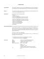
Conventions
Note:
Footnote for item marked with Note in the text
Caution:
Information requiring particular attention
Remark:
Supplementary information
Numeric representation:
Binary ... xxxx or xxxxB
Decimal ... xxxx
Hexadecimal ... xxxxH
“ ”:
Indicates an arbitrary message or item on the screen.
[ ]:
indicates the name of a button, command, dailog box, or
area.
4
User’s Manual U18591EJ2V0UM
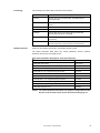
Terminology
The meanings of the terms used in this manual are as follows.
Term
Meaning
General name that means MINICUBE2, 78K0 MINICUBE and
Emulator
78K0S MINICUBE+
MINICUBE2
Indicates QB-MINI2, an on-chip debug emulator with programming
78K0 MINICUBE
Indicates 78K0 on-chip debug emulator QB-78K0MINI.
78K0S MINICUBE+
Indicates 78K0S/Kx1+ in-circuit emulator QB-78K0SKX1MINI.
Debugger
Indicates NEC Electronics integrated debugger ID78K0-QB,
function.
ID78K0S-QB, ID78K0R-QB, or ID850QB.
Indicates the QB-Programmer, GUI software used for flash
QBP
programming.
Binary file that contains device-dependent information. It is prepared
Device file
for each target device or group of devices in the same lineup.
Related Documents
Please use the following documents in combination with this manual.
The related documents listed below may include preliminary versions. However,
preliminary versions are not marked as such.
{ Documents Related to Development Tools (User’s Manuals)
Document Name
Document Number
MINICUBE OCD Checker
This manual
QB-MINI2 On-Chip Debug Emulator with Programming Function
U18371E
QB-78K0MINI On-Chip Debug Emulator
U17029E
ID78K0-QB Ver. 2.90 Integrated Debugger Operation
U17437E
QB-78K0SKX1MINI In-Circuit Emulator
U17272E
ID78K0S-QB Ver. 2.90 Integrated Debugger Operation
U18247E
ID78K0R-QB Ver. 3.20 Integrated Debugger Operation
U17839E
ID850QB Ver. 3.20 Integrated Debugger Operation
U17435E
QB-Programmer Programming GUI Operation
U18527E
MINICUBE2 Diagnostic Tool
U18588E
Caution The related documents listed above are subject to change without notice.
Be sure to use the latest version of each document for designing, etc.
User’s Manual U18591EJ2V0UM
5
CONTENTS
CHAPTER 1 OVERVIEW............................................................................................................................8
1.1
1.2
1.3
MINICUBE OCD Checker ............................................................................................................. 8
Target Emulators and Items to Be Checked.............................................................................. 8
Notes Before Using OCD Checker.............................................................................................. 9
CHAPTER 2 INSTALLATION AND STARTUP........................................................................................10
2.1
2.2
2.3
When NEC Electronics Tool Is Used ........................................................................................ 10
2.1.1
Installation...................................................................................................................................... 10
2.1.2
Startup ........................................................................................................................................... 10
When Tools Manufactured by Partner Companies (GHS and IAR) are Used....................... 11
2.2.1
Installation...................................................................................................................................... 11
2.2.2
Startup ........................................................................................................................................... 11
Explanation of Each Area.......................................................................................................... 12
CHAPTER 3 OCD CHECK FOR MINICUBE2 AND 78K0 MICROCONTROLLER .................................14
3.1
3.2
3.3
3.4
Execution of OCD Check ........................................................................................................... 14
Format of Log File ...................................................................................................................... 16
Error Output................................................................................................................................ 17
Action for Error........................................................................................................................... 18
CHAPTER 4 OCD CHECK FOR MINICUBE2 AND V850 MICROCONTROLLER .................................20
4.1
4.2
4.3
4.4
Execution of OCD Check ........................................................................................................... 20
Format of Log File ...................................................................................................................... 22
Error Output................................................................................................................................ 23
Action for Error........................................................................................................................... 24
CHAPTER 5 OCD CHECK FOR MINICUBE2 AND 78K0S MICROCONTROLLER...............................26
5.1
5.2
5.3
5.4
Execution of OCD Check ........................................................................................................... 26
Format of Log File ...................................................................................................................... 28
Error Output................................................................................................................................ 29
Action for Error........................................................................................................................... 30
CHAPTER 6 OCD CHECK FOR MINICUBE2 AND 78K0R MICROCONTROLLER...............................32
6.1
6.2
6.3
6.4
Execution of OCD Check ........................................................................................................... 32
Format of Log File ...................................................................................................................... 34
Error Output................................................................................................................................ 35
Action for Error........................................................................................................................... 36
CHAPTER 7 OCD CHECK FOR 78K0 MINICUBE ..................................................................................38
7.1
7.2
7.3
7.4
6
Execution of OCD Check ........................................................................................................... 38
Format of Log File ...................................................................................................................... 40
Error Output................................................................................................................................ 41
Action for Error........................................................................................................................... 43
User’s Manual U18591EJ2V0UM
CHAPTER 8 OCD CHECK FOR 78K0S MINICUBE+ .............................................................................44
8.1
8.2
8.3
8.4
Execution of OCD Check........................................................................................................... 44
Format of Log File...................................................................................................................... 46
Error Output................................................................................................................................ 47
Action for Error .......................................................................................................................... 48
CHAPTER 9 OCD CHECKER VERSION INDICATION...........................................................................50
CHAPTER 10 UNINSTALLATION ...........................................................................................................51
APPENDIX A REVISION HISTORY ..........................................................................................................52
A.1
Major Revisions in This Edition................................................................................................ 52
User’s Manual U18591EJ2V0UM
7
CHAPTER 1 OVERVIEW
1.1
MINICUBE OCD Checker
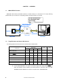
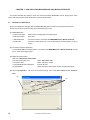
MINICUBE OCD Checker (hereinafter referred to as OCD Checker) is a self-check tool for simply detecting
problems that may occur when an on-chip debug emulator and target system are connected.
The OCD Checker checks if
the communication circuits
operate normally.
Communication circuits
must be mounted on
the target system.
Target device
USB
communication
Serial communication
MINICUBE2
Host machine
Target system
1.2
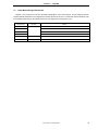
Target Emulators and Items to Be Checked
The following table lists the items that can be checked with the OCD Checker.
MINICUBE2
Check Items
78K0
V850
78K0S
78K0
78K0S
MINICUBE
MINICUBE+
√
√
√
√
√
78K0R
Status of main clock
√
Status of target power supply
√
√
Status of RESET pin
√
√
√
√
√
√
Hardware version indication
√
√
√
√
√
√
ID verification
√
√
√
√
Download of flash memory data
√
√
√
√
√
Program execution and stop operation
√
√
√
√
√
√
√
√
√
Erasure of flash memory data
Remark 1.
2.
√ : Available
blank : Unavailable
For the 78K0S MINICUBE+, the system clock status, target power supply status, RESET pin
status and hardware version indication are checked, based on connection check of the QB78K0SMINI and QB-78K0SKX1-DA, both are components of the 78K0S MINICUBE+.
8
User’s Manual U18591EJ2V0UM
CHAPTER 1 OVERVIEW
1.3
Notes Before Using OCD Checker
Chapters 1 and 2 present an overview and basic specifications of the OCD Checker, and the following sections
provide separate description for the target device and the emulator to be used. To utilize this manual effectively, refer
to the following table and see the relevant section for your target device and purpose of use.
Target Device
78K0
Emulator
MINICUBE2
Refer to:
CHAPTER 3 OCD CHECK FOR MINICUBE2 AND 78K0 MICROCONTROLLER
V850
CHAPTER 4 OCD CHECK FOR MINICUBE2 AND V850 MICROCONTROLLER
78K0S
CHAPTER 5 OCD CHECK FOR MINICUBE2 AND 78K0S MICROCONTROLLER
78K0R
CHAPTER 6 OCD CHECK FOR MINICUBE2 AND 78K0R MICROCONTROLLER
78K0
78K0 MINICUBE
CHAPTER 7 OCD CHECK FOR 78K0 MINICUBE
78K0S
78K0S MINICUBE+
CHAPTER 8 OCD CHECK FOR 78K0S MINICUBE+
User’s Manual U18591EJ2V0UM
9
CHAPTER 2 INSTALLATION AND STARTUP
This section explains how to install and start the OCD Checker.
2.1
When NEC Electronics Tool Is Used
2.1.1 Installation
• Select the “Emulator Utilities” check box when installing CubeSuite V1.00 or later. The MINICUBE OCD
<R>
Checker is then installed automatically.
• Select the “MINICUBE Utilities Vx.xx” check box when installing ID78K0-QB V2.93 or later. The OCD Checker
is then installed automatically.
• Select the “MINICUBE Utilities Vx.xx” check box when installing ID850QB V3.20 or later. The OCD Checker is
then installed automatically.
• Select the “MINICUBE Utilities Vx.xx” check box when installing QBP V1.00 or later. The OCD Checker is then
installed automatically.
• Select the “MINICUBE Utilities Vx.xx” check box when installing ID78K0S-QB V2.82 or later. The OCD Checker
is then installed automatically.
• Select the “MINICUBE Utilities Vx.xx” check box when installing ID78K0R-QB V3.20 or later.
The OCD
Checker is then installed automatically.
Caution
If multiple debuggers are installed, “MINICUBE Utilities Vx.xx MINICUBE OCD Checker” in the
[Latest Version] folder is overwritten. When an ID78K0-QB or ID78K0S-QB earlier than V3.00
is installed, the OCD Checker in the [NEC Tools32] folder is overwritten.
Remark
The MINICUBE2 diagnostic tool is installed when the OCD Checker is installed.
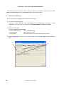
<R> 2.1.2 Startup
Start the OCD Checker using either of the following procedure.
• When using CubeSuite
Click the Start menu of Windows, point to “Programs”, “NEC Electronics CubeSuite”, “Emulator Utilities”,
“<Target Device>”and then click “OCD Checker”.
• When using the ID850QB, ID78K0-QB, ID78K0S-QB, ID78K0R-QB, or QB-Programmer
Start OCD Checker by using either of the following methods.
• Click the Start menu of Windows, point to “Programs”, “NEC Electronics Tools”, “Latest Version”, and then
click “MINICUBE Utilities Vx.xx OCD Checker”.
• Click the Start menu of Windows, point to “Programs”, “NEC Tools32”, and then click “OCD Checker”. (For
an ID78K0-QB or ID78K0S-QB earlier than V3.00)
10
User’s Manual U18591EJ2V0UM
CHAPTER 2 INSTALLATION AND STARTUP
Caution
If the debugger, QBP, or MINICUBE2 diagnostic tool is running, terminate it before starting the
OCD Checker.
Remark
When an ID78K0-QB or ID78K0S-QB earlier than V3.00, a link file for startup is created in the [NEC
Tools32] and [NEC Electronics Utilities] folders.
2.2
When Tools Manufactured by Partner Companies (GHS and IAR) are Used
2.2.1 Installation
• Download MINICUBE Utilities (MINICUBE_Utilities_Vxxx.lzh) from one of the following websites.
http://www.necel.com/micro/ghs/jpn/exec/execindex.html (Japanese version)
http://www.necel.com/micro/ghs/eng/exec/ (English version)
<1> Download MINICUBE_Utilities_Vxxx.lzh into an arbitrary folder from the website.
<2> Execute MINICUBE_Utilities_Vxxx.lzh in the arbitrary folder.
<3> The following folders and files will be created in the arbitrary folder.
MINICUBE_Utilities_Vxxx
MINICUBE_Utilities_Vxxx
MINICUBE_Utilities_Document_Vxxx
readme_j.txt
readme_e.txt
<4> Install MINICUBE_Utilities_Vxxx main unit as follows.
• If the OS is Japanese Windows, execute setup.exe in the MINICUBE_Utilities_Vxxx\Japanese\DISK1
folder and install the software according to the installer instructions.
• If the OS is not Japanese Windows, execute setup.exe in the MINICUBE_Utilities_Vxxx\English\DISK1
folder and install the software according to the installer instructions.
Caution
Specify C:\Program Files\NEC Electronics Tools as an installation destination folder.
Remarks 1. The MINICUBE OCD Checker and MINICUBE2 diagnostic tool can be installed by installing
MINICUBE Utilities Vxxx.
2. GHS: Green Hills Software, Inc
IAR: IAR Systems AB
2.2.2 Startup
• Click the Start menu of Windows, point to “Programs”, “NEC Electronics Tools”, “Latest Version”, and then click
“MINICUBE Utilities Vx.xx OCD Checker”.
Caution
If the debugger, QBP, or MINICUBE2 diagnostic tool is running, terminate it before starting
the OCD Checker.
User’s Manual U18591EJ2V0UM
11
CHAPTER 2 INSTALLATION AND STARTUP
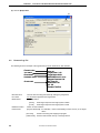
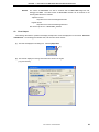
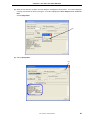
2.3
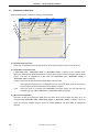
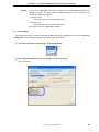
Explanation of Each Area
When the OCD Checker is started, the following window appears.
(11)
(3)
(1)
(4)
(2)
(5)
(10)
(7)
(6)
(8)
(9)
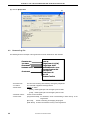
(1) Emulator mode select area
Select from the drop-down list the emulator mode for which target connection check is to be performed.
(2) Target Device Connection area
If “MINICUBE2 V850”, “MINICUBE2 78K0S” or “MINICUBE2 78K0R” is selected for the emulator mode,
specify from the drop-down list the device file for the target device and the mode for connection with the target
system.
This menu is unavailable if an item other than “MINICUBE2 V850”, “MINICUBE2 78K0S” or
“MINICUBE2 78K0R” is selected.
• Device: Select from the drop-down list the target device to be connected.
If the target device (device file) is not displayed in the list, specify the folder where the device file is
• Port:
saved, using the (3) [Device file folder] button in the above window.
Select the mode for connection with MINICUBE2 and target system from the drop-down list
(available only when “MINICUBE2 V850” or “MINICUBE2 78K0R” is selected)
(3) [Device file folder] button
This button is used for searching the folder where the device file is saved to define the device file to be
connected when “MINICUBE2 V850”, “MINICUBE2 78K0S”, or “MINICUBE2 78K0R” is selected. When the
device file has been installed using the device file installer (DFINDT), the saved folder is automatically
specified.
12
User’s Manual U18591EJ2V0UM
CHAPTER 2 INSTALLATION AND STARTUP
(4) Clock select area
Select with the radio button the clock supplied to the emulator.
• internal:
When a clock mounted in the emulator is used.
• socket:
When a clock mounted in the CLK1 socket of the MINICUBE2 78K0-OCD board and a
clock mounted in the CLK1 socket of the 78K0 MINICUBE or 78K0S MINICUBE+ are used.
• Main OSC(MHz): Input the target system clock frequency when “MINICUBE2 V850” is selected.
(5) Internal ROM Security setting area
To set the ID code, select the “ID Code” check box; otherwise, the ID code is handled as 0xFF.
If “MINICUBE2 V850” is selected, this area is available only when a debug monitor program has been written
to the target device.
This area is unavailable if “MINICUBE2 78K0S” or “78K0S MINICUBE+” is selected for the emulator mode.
(6) [Log file] button
Specifies the file to which the check log will be output (log file).
The location for saving the log file can be changed by clicking the [Log file] button. The log file is created as
“IEOCDUTL.log” in a temporary folder by default. Normally, the temporary folder is specified in the tmp or
temp environmental variable.
(7) [Test] button
Starts checking. The checked items and their result are output to the log file.
(8) Log view window
Displays the check result. The contents displayed in this area are also output to the log file that is specified
using the (6) [Log file] button.
(9) [Clear] button
Clears the log view window. The contents output to the log file are not cleared.
(10) [Exit] button
Terminates the OCD Checker.
(11) System menu
Version can be checked by clicking “About OCD Checker...” on the System menu.
Remark
Settings for the OCD Checker are maintained when the OCD Checker is started the next time,
except for the setting in the Internal ROM Security setting area.
User’s Manual U18591EJ2V0UM
13
CHAPTER 3 OCD CHECK FOR MINICUBE2 AND 78K0 MICROCONTROLLER
This section describes the method to check the connection between MINICUBE2 and the target system, which
uses a 78K0 microcontroller as the target device, using the OCD Checker.
3.1
Execution of OCD Check
Be sure to terminate the debugger, QBP and MINICUBE2 diagnostic tool before executing the OCD Checker.
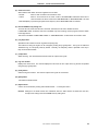
Perform the connection check according to the following steps (1) to (6).
(1) MINICUBE2 setup
• Power select switch:
• Mode select switch:
Set the switch corresponding to the target system.
Set to “M2”.
• 78K0-OCD board:
Connect the board in accordance with MINICUBE2 User’s Manual (U18371E).
• Target cable:
Connect the cable having a pin count corresponding to the target system (16- pin or
10-pin).
(2) Connection and power application
Connect MINICUBE2 to the target system in accordance with MINICUBE2 User’s Manual (U18371E), and the
turn on power to the target system.
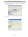
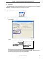
(3) Setting the OCD Checker
Refer to 2.3 Explanation of Each Area.
• Emulator mode select area:
Select “MINICUBE2 78K0”.
• Clock select area:
Select “internal” or “socket”.
• Internal ROM Security setting area:
Input the ID code.
• [Log file] button:
Specify the log file name and the location for saving the log file.
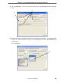
(4) Click the [Test] button. If an error occurs during checking, refer to 3.3 Error Output and 3.4 Action for
Error.
(4)
(3)
14
User’s Manual U18591EJ2V0UM
CHAPTER 3 OCD CHECK FOR MINICUBE2 AND 78K0 MICROCONTROLLER
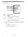
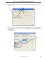
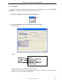
(5) When all of the tests are complete, the result dialog box is displayed as shown below. The contents displayed
in the log view window are saved in the log file. If an NG is displayed, refer to 3.3 Error Output and 3.4
Action for Error. Click the [OK] button.
(5)
(6) Click the [Exit] button.
(6)
User’s Manual U18591EJ2V0UM
15
CHAPTER 3 OCD CHECK FOR MINICUBE2 AND 78K0 MICROCONTROLLER
3.2
Format of Log File
The following shows an example of the log file when the check results show “OK” statuses.
Execution time
Clock status
VDD status
Reset status
tt:mm:ss
Target Clock: 20.00MHz [OK]
Target Power: 5.1V [OK]
Target Reset: HIGH
OCD Control Code Vx.xx
MINICUBE2 4100 x xx.xx
Program Download: OK
Run Test: OK
Flash Erase: OK
ALL OK
Emulator Test End
Hardware version
Check result
• Execution time:
The time when checking was started by clicking the [Test] button
• Clock status:
Frequency of the selected clock
• VDD status:
VDD value that is applied to the target device
• Reset status:
RESET pin status
[HIGH]
Reset signal input from the target system is HIGH
• Hardware version:
[LOW]
Reset signal input from the target system is LOW
Version of each hardware.
• Check result:
[Program Download] ID verification, result of downloading to flash memory in the target
device
Remark
[Run Test]
Result of executing and stopping the program
[Flash Erase]
Erasure result of flash memory in the target device
The version of MINICUBE2 can also be checked with the MINICUBE2 diagnostic tool, debugger and
QBP. The latest version of MINICUBE2 firmware can be checked on the following NEC Electronics
websites.
Japanese version:
http://www.necel.com/micro/ods/jpn/index.html
English version:
http://www.necel.com/micro/ods/eng/index.html
See Version-up service → MINICUBE2_Software.
16
User’s Manual U18591EJ2V0UM
CHAPTER 3 OCD CHECK FOR MINICUBE2 AND 78K0 MICROCONTROLLER
3.3
Error Output
The following describes the operation and display example when an NG is displayed as a result of 3.1 Execution
of OCD Check. The message just indicates “NG”, but there are various causes.
(1) The result is displayed in the dialog box. Click the [OK] button.
(1)
(2) The contents displayed in the log view window are saved in the log file.
[Log view window]
[Log file]
Execution time
Clock status = OK
Error indication
Hardware version
tt:mm:ss
Target Clock: 20.00MHz [OK]
Monitor Command(3FH) Error
Communication Error
MINICUBE2 4100 x xx.xx
Emulator Test End
In this NG example, the monitor command (3FH) error and communication error are output.
The communication failure between the target device and MINICUBE2 is detected. The cause is an error in
the target cable connection between the target system and MINICUBE2.
User’s Manual U18591EJ2V0UM
17
CHAPTER 3 OCD CHECK FOR MINICUBE2 AND 78K0 MICROCONTROLLER
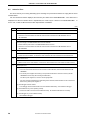
3.4
Action for Error
The errors that may occur during self-testing (such as setting error) and relevant actions for coping with the errors
are listed below.
If an error other than below is displayed, the cause may be a defect in MINICUBE2. If the same error is displayed
even after the relevant action is implemented, the cause may be a defect in MINICUBE2. In such a case, consult an
NEC Electronics sales representative or distributor.
(1/2)
No.
Error message and action
1
Communication error
There is no response from the target device.
→ Address 0x84 (on-chip debug emulator use enable flag) is set to 0x00 (disable use) or the target system and
MINICUBE2 are not connected correctly.
Confirm the file of the program written to the target device and connection between the target system and
MINICUBE2.
2
Target Power : 0.0V [NG]
The power supply to the target system cannot be detected.
→ Confirm that the power for the target system is on.
→ Check the connection between the target system and MINICUBE2
3
78K0 OCD board is not connected
The 78K0-OCD board is not connected.
→ Confirm that the 78K0-OCD board is connected.
4
Target Clock: 0.00MHz [NG]
The clock mounted in the CLK1 socket may not be operating.
→ Confirm the clock oscillation, or remove the clock mounted in the CLK1 socket in the 78K0-OCD board and
use the internal clock.
5
Select Socket Clock
The clock mounted in the CLK1 socket is not selected.
→ Select “socket” for the clock setting, or remove the clock mounted in the CLK1 socket and select “internal”.
6
Driver open error
(1) There is no response from MINICUBE2.
→ Check the connections between the host machine and the USB cable, and the USB cable and the
MINICUBE2.
→ Turn all the power supplies off according to the procedures described in the user’s manual. (MINICUBE2 is
turned off by disconnecting the USB cable.)
Turn all the power supplies on, and then click the [Test] button.
If an error message is displayed even after taking these measures, restart Windows on the host machine
before turning all the power supplies on.
(2) The debugger has been started.
→ The debugger and the OCD Checker cannot be started simultaneously, so terminate the debugger.
(3) The USB driver may not be operating normally.
→ Confirm the cable connection and the USB driver setup. Re-install the USB driver as necessary.
(4) The debugger may not be installed normally.
→ Re-install the debugger.
18
User’s Manual U18591EJ2V0UM
CHAPTER 3 OCD CHECK FOR MINICUBE2 AND 78K0 MICROCONTROLLER
(2/2)
No.
Error message and action
7
Incorrect ID code
The input ID code is incorrect.
→ Confirm the ID code written to the target device and re-input the ID code.
8
Log file write error
The specified log file cannot be accessed.
→ Confirm that the folder, path, and file are write-enabled.
9
Test Rom Command(xxH) Error, Monitor Command(xxH) Error
Communication between the target device and MINICUBE2 has failed.
→ The cause may be a problem in the electrical specifications of the cable or the target system, or the USB
driver may not be operating normally.
Confirm the connection and restart Windows on the host machine.
10
Write Memory, Read Memory, Data verify error
The internal RAM cannot be accessed. The target device may be damaged.
→ Exchange the target device.
11
_Flash Env Error, _Flash Get Info Error, _Flash Block Blank Check Error, _Flash Block Erase Error, _Flash Word
Write Error, _Flash Block Verify Error, _Flash Word Read Error, Data Verify Error
An error occurred while writing to the flash memory.
→ The cause may be the security flag setting, so clear the security flag setting via the QBP.
The target device may be damaged, so exchange the target device.
12
Break Timeout, ERROR: SP Break Test, ERROR: Execute Break Test1, ERROR: SFR Access Break Test,
ERROR: Read Access Break Test1, ERROR: Read Access Break Test2, ERROR: Write Access Break Test1,
ERROR: Write Access Break Test2, ERROR: Step Break Test, ERROR: Execute Break Test2
The target device may be damaged, so exchange the target device.
User’s Manual U18591EJ2V0UM
19
CHAPTER 4 OCD CHECK FOR MINICUBE2 AND V850 MICROCONTROLLER
This section describes the method to check the connection between MINICUBE2 and the target system, which
uses a V850 microcontroller as the target device, using the OCD Checker.
4.1
Execution of OCD Check
Be sure to terminate the debugger, QBP and MINICUBE2 diagnostic tool before executing the OCD Checker.
The 78K0-OCD board and 10-pin target cable (accessories of MINICUBE2) are not used.
Perform the connection check according to the following steps (1) to (6).
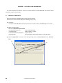
(1) MINICUBE2 setup
• Power select switch:
Set the switch corresponding to the target system.
• Mode select switch:
Set to “M2”.
• Target cable:
Connect the 16- pin target cable.
(2) Connection and power application
Connect MINICUBE2 to the target system in accordance with MINICUBE2 User’s Manual (U18371E), and the
turn on power to the target system.
(3) Setting the OCD Checker
Refer to 2.3 Explanation of Each Area.
• Emulator mode select area:
Select “MINICUBE2 V850”.
• Target Device Connection area:
[Device] Select the target device to be connected from the drop-down
list.
If the target device name is not displayed, specify the device
file saving destination folder using the [Device file folder] button.
[Port]
• Clock select area:
Select the mode for connection with target system from the
drop-down list.
Input the original main clock frequency in the “Main OSC(MHz)” text box.
• Internal ROM Security setting area: Input the ID code.
• [Log file] button:
20
Specify the log file name and the location for saving the log file.
User’s Manual U18591EJ2V0UM
CHAPTER 4 OCD CHECK FOR MINICUBE2 AND V850 MICROCONTROLLER
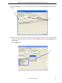
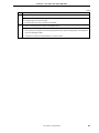
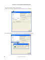
(4) Click the [Test] button. If an error occurs during checking, refer to 4.3 Error Output and 4.4 Action for
Error.
(3)
(4)
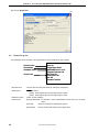
(5) When all of the tests are complete, the result dialog box is displayed as shown below. The contents displayed
in the log view window are saved in the log file. If an NG is displayed, refer to 4.3 Error Output and 4.4
Action for Error.
Click the [OK] button.
(5)
User’s Manual U18591EJ2V0UM
21
CHAPTER 4 OCD CHECK FOR MINICUBE2 AND V850 MICROCONTROLLER
(6) Click the [Exit] button.
(6)
4.2
Format of Log File
The following shows an example of the log file when the check results show “OK” statuses.
Execution time
VDD status
Reset status
Hardware version
tt:mm:ss
Target Power: 3.2V
Target Reset: HIGH
MINICUBE2 4100 x xx.xx
Program Download: OK
Run Test: OK
Flash Erase: OK
ALL OK
Emulator Test End
Check result
• Execution time:
The time when checking was started by clicking the [Test] button
• VDD status:
VDD value that is applied to the target device
• Reset status:
RESET pin status
[HIGH]
Reset signal input from the target system is HIGH
• Hardware version:
[LOW]
Reset signal input from the target system is LOW
Version of each hardware.
• Check result:
[Program Download] ID verification, result of downloading to flash memory in the target
device
22
[Run Test]
Result of executing and stopping the program
[Flash Erase]
Erasure result of flash memory in the target device
User’s Manual U18591EJ2V0UM
CHAPTER 4 OCD CHECK FOR MINICUBE2 AND V850 MICROCONTROLLER
Remark
The version of MINICUBE2 can also be checked with the MINICUBE2 diagnostic tool,
debugger and QBP. The latest version of MINICUBE2 firmware can be checked on the
following NEC Electronics websites.
Japanese version:
http://www.necel.com/micro/ods/jpn/index.html
English version:
http://www.necel.com/micro/ods/eng/index.html
See Version-up service → MINICUBE2_Software.
4.3
Error Output
The following describes the operation and display example when an NG is displayed as a result of 4.1 Execution
of OCD Check. The message just indicates “NG”, but there are various causes.
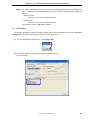
(1) The result is displayed in the dialog box. Click the [OK] button.
(1)
(2) The contents displayed in the log view window are saved in the log file.
[Log view window]
User’s Manual U18591EJ2V0UM
23
CHAPTER 4 OCD CHECK FOR MINICUBE2 AND V850 MICROCONTROLLER
[Log file]
Execution time
VDD status = OK
Reset status = OK
Hardware version
Error indication
tt:mm:ss
Target Power: 3.2V
Target Reset: HIGH
MINICUBE2 4100 x xx.xx
Program Download: NG
Emulator Test End
In this NG example, the error “Program Download” is detected.
An error during flash memory programming is detected. The cause is an error in pin connection on the board
for connecting MINICUBE2 on the target system (pin 5 (SO) is shorted with GND).
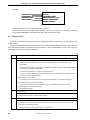
4.4
Action for Error
The errors that may occur during self-testing (such as setting error) and relevant actions for coping with the errors
are listed below.
If an error other than below is displayed, the cause may be a defect in MINICUBE2. If the same error is displayed
even after the relevant action is implemented, the cause may be a defect in MINICUBE2. In such a case, consult an
NEC Electronics sales representative or distributor.
(1/2)
No.
Error message and action
1
Driver open error
(1) There is no response from MINICUBE2.
→ Check the connections between the host machine and the USB cable, and the USB cable and the
MINICUBE2.
→ Turn all the power supplies off according to the procedures described in the user’s manual. (MINICUBE2 is
turned off by disconnecting the USB cable.)
Turn all the power supplies on, and then click the [Test] button.
If an error message is displayed even after taking these measures, restart Windows on the host machine
before turning all the power supplies on.
(2) The debugger has been started.
→ The debugger and the OCD Checker cannot be started simultaneously, so terminate the debugger.
(3) The USB driver may not be operating normally.
→ Confirm the cable connection and the USB driver setup. Re-install the USB driver as necessary.
(4) The debugger may not be installed normally.
→ Re-install the debugger.
2
Incorrect ID code
The input ID code is incorrect.
→ Confirm the ID code written to the target device and re-input the ID code.
3
Log file write error
The specified log file cannot be accessed.
→ Confirm that the folder, path, and file are write-enabled.
24
User’s Manual U18591EJ2V0UM
CHAPTER 4 OCD CHECK FOR MINICUBE2 AND V850 MICROCONTROLLER
(2/2)
No.
Error message and action
4
Cannot find monitor file
Check if an unsupported device or unsupported port is selected.
5
Monitor Command(xxH) Error
Communication between the target device and MINICUBE2 has failed.
→ The cause may be a problem in the electrical specifications of the cable or the target system, or the USB
driver may not be operating normally.
Confirm the connection and restart Windows on the host machine.
6
Emulator Command(xxH) Error
Communication between the host machine and MINICUBE2 has failed.
(1) Check the connections between the host machine and the USB cable, and the USB cable and the
MINICUBE2.
(2) Turn all the power supplies off according to the procedures described in the user’s manual. (MINICUBE2 is
turned off by disconnecting the USB cable.)
Turn all the power supplies on, and then click the [Test] button.
If an error message is displayed even after taking these measures, restart Windows on the host machine
before turning all the power supplies on.
7
Program Download : NG
An error occurred while writing to the flash memory.
(1) Check if the items specified in the Target Device Connection area and clock select area satisfy the target
device specifications.
(2) Check the connections between the target device and MINICUBE2.
(3) Check the power supply to the target system.
(4) The cause may be the security flag setting, so clear the security flag setting via the flash memory
programmer.
(5) The target device may be damaged, so exchange the target device.
(6) Check the MINICUBE2 settings.
(7) Check the circuit for connecting MINICUBE2.
8
Break Timeout, ERROR: Execute Break Test1, ERROR: Read Access Break Test, ERROR: Write Access Break
Test, ERROR: Execute Break Test2
The target device may be damaged, so exchange the target device.
9
Target Power : 0.0V [NG]
The power supply to the target system cannot be detected.
→ Confirm that the power for the target system is on.
→ Check the connection between the target system and MINICUBE2
10
Use the firmware version Vx.xx or later
Update MINICUBE2 firmware to Vx.xx or later.
User’s Manual U18591EJ2V0UM
25
CHAPTER 5 OCD CHECK FOR MINICUBE2 AND 78K0S MICROCONTROLLER
This section describes the method to check the connection between MINICUBE2 and the target system, which
uses a 78K0S microcontroller as the target device, using the OCD Checker.
5.1
Execution of OCD Check
Be sure to terminate the debugger, QBP and MINICUBE2 diagnostic tool before executing the OCD Checker.
The 78K0-OCD board and 10-pin target cable (accessories of MINICUBE2) are not used.
Perform the connection check according to the following steps (1) to (6).
(1) MINICUBE2 setup
• Power select switch:
Set the switch corresponding to the target system.
• Mode select switch:
Set to “M2”.
• Target cable:
Connect the 16- pin target cable.
(2) Connection and power application
Connect MINICUBE2 to the target system in accordance with MINICUBE2 User’s Manual (U18371E), and the
turn on power to the target system.
(3) Setting the OCD Checker
Refer to 2.3 Explanation of Each Area.
• Emulator mode select area:
Select “MINICUBE2 78K0S”.
• Target Device Connection area:
[Device]
Select the target device to be connected from the drop-down
list.
If the target device name is not displayed, specify the device
file saving destination folder using the [Device file folder]
• [Log file] button:
26
button.
Specify the log file name and the location for saving the log file.
User’s Manual U18591EJ2V0UM
CHAPTER 5 OCD CHECK FOR MINICUBE2 AND 78K0S MICROCONTROLLER
(4) Click the [Test] button. If an error occurs during checking, refer to 5.3 Error Output and 5.4 Action for
Error.
(4)
(3)
(5) When all of the tests are complete, the result dialog box is displayed as shown below. The contents displayed
in the log view window are saved in the log file. If an NG is displayed, refer to 5.3 Error Output and 5.4
Action for Error.
Click the [OK] button.
(5)
User’s Manual U18591EJ2V0UM
27
CHAPTER 5 OCD CHECK FOR MINICUBE2 AND 78K0S MICROCONTROLLER
(6) Click the [Exit] button.
5.2
(6)
Format of Log File
The following shows an example of the log file when the check results show “OK” statuses.
Execution time
Reset status
Hardware version
tt:mm:ss
Target Reset: HIGH
MINICUBE2 4100 x xx.xx
Program Download: OK
Run Test: OK
Flash Erase: OK
ALL OK
Emulator Test End
Check result
• Execution time:
The time when checking was started by clicking the [Test] button
• Reset status:
RESET pin status
[HIGH]
Reset signal input from the target system is HIGH
• Hardware version:
[LOW] Reset signal input from the target system is LOW
Version of each hardware.
• Check result:
[Program Download] ID verification, result of downloading to flash memory in the target
device
28
[Run Test]
Result of executing and stopping the program
[Flash Erase]
Erasure result of flash memory in the target device
User’s Manual U18591EJ2V0UM
CHAPTER 5 OCD CHECK FOR MINICUBE2 AND 78K0S MICROCONTROLLER
Remark The version of MINICUBE2 can also be checked with the MINICUBE2 diagnostic tool, debugger and
QBP. The latest version of MINICUBE2 firmware can be checked on the following NEC Electronics
websites.
Japanese version:
http://www.necel.com/micro/ods/jpn/index.html
English version:
http://www.necel.com/micro/ods/eng/index.html
See Version-up service → MINICUBE2_Software.
5.3
Error Output
The following describes the operation and display example when an NG is displayed as a result of 5.1 Execution
of OCD Check. The message just indicates “NG”, but there are various causes.
(1) The result is displayed in the dialog box. Click the [OK] button.
(1)
(2) The contents displayed in the log view window are saved in the log file.
[Log view window]
User’s Manual U18591EJ2V0UM
29
CHAPTER 5 OCD CHECK FOR MINICUBE2 AND 78K0S MICROCONTROLLER
[Log file]
Execution time
Reset status = OK
Hardware version
Error indication
tt:mm:ss
Target Reset: HIGH
MINICUBE2 4100 x xx.xx
Program Download:NG
Emulator Test End
In this NG example, the error “Program Download” is detected.
An error during flash memory programming is detected. The cause is an error in pin connection on the board
for connecting MINICUBE2 on the target system (pin 5 (SO) is shorted with GND).
5.4
Action for Error
The errors that may occur during self-testing (such as setting error) and relevant actions for coping with the errors
are listed below.
If an error other than below is displayed, the cause may be a defect in MINICUBE2. If the same error is displayed
even after the relevant action is implemented, the cause may be a defect in MINICUBE2. In such a case, consult an
NEC Electronics sales representative or distributor.
(1/2)
No.
Error message and action
1
Driver open error
(1) There is no response from MINICUBE2.
→ Check the connections between the host machine and the USB cable, and the USB cable and the
MINICUBE2.
→ Turn all the power supplies off according to the procedures described in the user’s manual. (MINICUBE2 is
turned off by disconnecting the USB cable.)
Turn all the power supplies on, and then click the [Test] button.
If an error message is displayed even after taking these measures, restart Windows on the host machine
before turning all the power supplies on.
(2) The debugger has been started.
→ The debugger and the OCD Checker cannot be started simultaneously, so terminate the debugger.
(3) The USB driver may not be operating normally.
→ Confirm the cable connection and the USB driver setup. Re-install the USB driver as necessary.
(4) The debugger may not be installed normally.
→ Re-install the debugger.
2
Log file write error
The specified log file cannot be accessed.
→ Confirm that the folder, path, and file are write-enabled.
3
Monitor Command(xxH) Error
Communication between the target device and MINICUBE2 has failed.
→ The cause may be a problem in the electrical specifications of the cable or the target system, or the USB
driver may not be operating normally.
Confirm the connection and restart Windows on the host machine.
30
User’s Manual U18591EJ2V0UM
CHAPTER 5 OCD CHECK FOR MINICUBE2 AND 78K0S MICROCONTROLLER
(2/2)
No.
Error message and action
4
Emulator Command(xxH) Error
Communication between the host machine and MINICUBE2 has failed.
(1) Check the connections between the host machine and the USB cable, and the USB cable and the
MINICUBE2.
(2) Turn all the power supplies off according to the procedures described in the user’s manual. (MINICUBE2 is
turned off by disconnecting the USB cable.)
Turn all the power supplies on, and then click the [Test] button.
If an error message is displayed even after taking these measures, restart Windows on the host machine
before turning all the power supplies on.
(3) Check if the target device name matches the name specified in the [Device] drop-down list in the Target
Device Connection area.
5
Program Download : NG
An error occurred while writing to the flash memory.
(1) Check the connections between the target device and MINICUBE2.
(2) Check the power supply to the target system.
(3) The cause may be the security flag setting, so clear the security flag setting via the flash memory
programmer.
(4) The target device may be damaged, so exchange the target device.
(5) Check the MINICUBE2 settings.
(6) Check the circuit for connecting MINICUBE2.
6
Break Timeout, ERROR: Execute Break Test1
The target device may be damaged, so exchange the target device.
7
Use the firmware version Vx.xx or later
Update MINICUBE2 firmware to Vx.xx or later.
User’s Manual U18591EJ2V0UM
31
CHAPTER 6 OCD CHECK FOR MINICUBE2 AND 78K0R MICROCONTROLLER
This section describes the method to check the connection between MINICUBE2 and the target system, which
uses a 78K0R microcontroller as the target device, using the OCD Checker.
6.1
Execution of OCD Check
Be sure to terminate the debugger, QBP and MINICUBE2 diagnostic tool before executing the OCD Checker.
The 78K0-OCD board and 10-pin target cable (accessories of MINICUBE2) are not used.
Perform the connection check according to the following steps (1) to (6).
(1) MINICUBE2 setup
• Power select switch:
Set the switch corresponding to the target system.
• Mode select switch:
Set to “M1”.
• Target cable:
Connect the 16- pin target cable.
(2) Connection and power application
Connect MINICUBE2 to the target system in accordance with MINICUBE2 User’s Manual (U18371E), and the
turn on power to the target system.
(3) Setting the OCD Checker
Refer to 2.3 Explanation of Each Area.
• Emulator mode select area:
Select “MINICUBE2 78K0R”.
• Target Device Connection area:
[Device]
Select the target device to be connected from the dropdown list.
If the target device name is not displayed, specify the
device file saving destination folder using the [Device file
folder] button.
[Port]
32
Select the mode for connection with target system from the
• Clock select area:
drop-down list.
Input the original main clock frequency in the “Main OSC(MHz)” text
• Internal ROM Security setting area:
box.
Input the ID code.
• [Log file] button:
Specify the log file name and the location for saving the log file.
User’s Manual U18591EJ2V0UM
CHAPTER 6 OCD CHECK FOR MINICUBE2 AND 78K0R MICROCONTROLLER
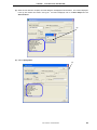
(4) Click the [Test] button. If an error occurs during checking, refer to 6.3 Error Output and 6.4 Action for
Error.
(3)
(4)
(5) When all of the tests are complete, the result dialog box is displayed as shown below. The contents displayed
in the log view window are saved in the log file. If an NG is displayed, refer to 6.3 Error Output and 6.4
Action for Error.
Click the [OK] button.
(5)
User’s Manual U18591EJ2V0UM
33
CHAPTER 6 OCD CHECK FOR MINICUBE2 AND 78K0R MICROCONTROLLER
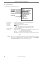
(6) Click the [Exit] button.
6.2
(6)
Format of Log File
The following shows an example of the log file when the check results show “OK” statuses.
Execution time
VDD status
Reset status
Hardware version
tt:mm:ss
Target Power: 3.2V [OK]
Target Reset: HIGH
MINICUBE2 4100 x xx.xx
Program Download: OK
Run Test: OK
Flash Erase: OK
ALL OK
Emulator Test End
Check result
• Execution time:
The time when checking was started by clicking the [Test] button
• VDD status:
VDD value that is applied to the target device
• Reset status:
RESET pin status
[HIGH] Reset signal input from the target system is HIGH
• Hardware version:
[LOW] Reset signal input from the target system is LOW
Version of each hardware.
• Check result:
[Program Download]
ID verification, result of downloading to flash memory in the
target device
34
[Run Test]
Result of executing and stopping the program
[Flash Erase]
Erasure result of flash memory in the target device
User’s Manual U18591EJ2V0UM
CHAPTER 6 OCD CHECK FOR MINICUBE2 AND 78K0R MICROCONTROLLER
Remark
The version of MINICUBE2 can also be checked with the MINICUBE2 diagnostic tool,
debugger and QBP. The latest version of MINICUBE2 firmware can be checked on the
following NEC Electronics websites.
Japanese version:
http://www.necel.com/micro/ods/jpn/index.html
English version:
http://www.necel.com/micro/ods/eng/index.html
See Version-up service → MINICUBE2_Software.
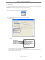
6.3
Error Output
The following describes the operation and display example when an NG is displayed as a result of 6.1 Execution
of OCD Check. The message just indicates “NG”, but there are various causes.
(1) The result is displayed in the dialog box. Click the [OK] button.
(1)
(2) The contents displayed in the log view window are saved in the log file.
[Log view window]
User’s Manual U18591EJ2V0UM
35
CHAPTER 6 OCD CHECK FOR MINICUBE2 AND 78K0R MICROCONTROLLER
[Log file]
Execution time
VDD status = OK
Reset status = OK
Hardware version
Error indication
tt:mm:ss
Target Power: 3.2V [OK]
Target Reset: HIGH
MINICUBE2 4100 x xx.xx
Program Download: NG
Emulator Test End
In this NG example, the error “Program Download” is detected.
An error during flash memory programming is detected. The cause is an error in pin connection on the board
for connecting MINICUBE2 on the target system (pin 3 (RXD) is shorted with GND).
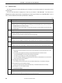
6.4
Action for Error
The errors that may occur during self-testing (such as setting error) and relevant actions for coping with the errors
are listed below.
If an error other than below is displayed, the cause may be a defect in MINICUBE2. If the same error is displayed
even after the relevant action is implemented, the cause may be a defect in MINICUBE2. In such a case, consult an
NEC Electronics sales representative or distributor.
(1/2)
No.
Error message and action
1
Driver open error
(1) There is no response from MINICUBE2.
→ Check the connections between the host machine and the USB cable, and the USB cable and the
MINICUBE2.
→ Turn all the power supplies off according to the procedures described in the user’s manual. (MINICUBE2 is
turned off by disconnecting the USB cable.)
Turn all the power supplies on, and then click the [Test] button.
If an error message is displayed even after taking these measures, restart Windows on the host machine
before turning all the power supplies on.
(2) The debugger has been started.
→ The debugger and the OCD Checker cannot be started simultaneously, so terminate the debugger.
(3) The USB driver may not be operating normally.
→ Confirm the cable connection and the USB driver setup. Re-install the USB driver as necessary.
(4) The debugger may not be installed normally.
→ Re-install the debugger.
2
Target Power : 0.0V [NG]
The power supply to the target system cannot be detected.
→ Confirm that the power for the target system is on.
→ Check the connection between the target system and MINICUBE2
3
Incorrect ID code
The input ID code is incorrect.
→ Confirm the ID code written to the target device and re-input the ID code.
36
User’s Manual U18591EJ2V0UM
CHAPTER 6 OCD CHECK FOR MINICUBE2 AND 78K0R MICROCONTROLLER
(2/2)
No.
Error message and action
4
Log file write error
The specified log file cannot be accessed.
→ Confirm that the folder, path, and file are write-enabled.
5
Monitor Command(xxH) Error
Communication between the target device and MINICUBE2 has failed.
→ The cause may be a problem in the electrical specifications of the cable or the target system, or the USB
driver may not be operating normally.
Confirm the connection and restart Windows on the host machine.
6
Emulator Command(xxH) Error
Communication between the host machine and MINICUBE2 has failed.
(1) Check the connections between the host machine and the USB cable, and the USB cable and the
MINICUBE2.
(2) Turn all the power supplies off according to the procedures described in the user’s manual. (MINICUBE2 is
turned off by disconnecting the USB cable.)
Turn all the power supplies on, and then click the [Test] button.
If an error message is displayed even after taking these measures, restart Windows on the host machine
before turning all the power supplies on.
(3) Check if the target device name matches the name specified in the [Device] drop-down list in the Target
Device Connection area.
7
Program Download : NG
An error occurred while writing to the flash memory.
(1) Check if the items specified in the Target Device Connection area and clock select area satisfy the target
device specifications.
(2) Check the connections between the target device and MINICUBE2.
(3) Check the power supply to the target system.
(4) The cause may be the security flag setting, so clear the security flag setting via the flash memory
programmer.
(5) The target device may be damaged, so exchange the target device.
(6) Check the MINICUBE2 settings.
(7) Check the circuit for connecting MINICUBE2.
8
Break Timeout, ERROR: Execute Break Test1
The target device may be damaged, so exchange the target device.
9
Use the firmware version Vx.xx or later
Update MINICUBE2 firmware to Vx.xx or later.
User’s Manual U18591EJ2V0UM
37
CHAPTER 7 OCD CHECK FOR 78K0 MINICUBE
This section describes the method to check the connection between the 78K0 MINICUBE and self-check board
(accessory), using the OCD Checker.
7.1
Execution of OCD Check
Be sure to terminate the debugger before executing the OCD Checker.
Perform the connection check according to the following steps (1) to (4).
(1) Connection
Connect the 78K0 MINICUBE to the self-check board in accordance with the 78K0 MINICUBE user’s manual.
(2) Setting the OCD Checker
Refer to 2.3 Explanation of Each Area.
• Emulator mode select area:
Select “78K0 MINICUBE”.
• Clock select area:
Select “internal” or “socket”.
• Internal ROM Security setting area:
Input the ID code.
• [Log file] button:
Specify the log file name and the location for saving the log file.
(3) Click the [Test] button. If an error occurs during checking, refer to 7.3 Error Output and 7.4 Action for
Error.
(3)
(2)
38
User’s Manual U18591EJ2V0UM
CHAPTER 7 OCD CHECK FOR 78K0 MINICUBE
(4) When all of the tests are complete, the result dialog box is displayed as shown below. The contents displayed
in the log view window are saved in the log file. If an NG is displayed, refer to 7.3 Error Output and 7.4
Action for Error.
(4)
(5) Click the [Exit] button.
(5)
User’s Manual U18591EJ2V0UM
39
CHAPTER 7 OCD CHECK FOR 78K0 MINICUBE
7.2
Format of Log File
The following shows an example of the log file.
Execution time
Clock status
VDD status
Reset status
tt:mm:ss
Target Clock: 5.00MHz [OK]
Target Power: 4.8V [OK]
Target Reset: HIGH
OCD Control Code Vx.xx
MINICUBE 78K0 4000 x x.xx
Program Download: OK
Run Test: OK
Flash Erase: OK
ALL OK
Emulator Test End
Hardware version
Check result
• Execution time:
The time when checking was started by clicking the [Test] button.
• Clock status:
Frequency of the selected clock
• VDD status:
VDD value that is applied to the self-check board
• Reset status:
RESET pin status
[HIGH]
Reset signal input from the self-check board is HIGH
• Hardware version:
[LOW] Reset signal input from the self-check board is LOW
Version of each hardware.
• Check result:
[Program Download]
ID verification, result of downloading to flash memory in the
target device (self-check board)
[Run Test]
Result of executing and stopping the program
[Flash Erase]
Erasure result of flash memory in the target device (self-check
board)
Remark
The version of the 78K0 MINICUBE can also be checked with the debugger. For the latest
version, consult an NEC Electronics sales representative or distributor. See QB-78K0MINI
User’s Manual (U17029E) for the control code of the OCD Checker.
40
User’s Manual U18591EJ2V0UM
CHAPTER 7 OCD CHECK FOR 78K0 MINICUBE
7.3
Error Output
The following describes the operation and display example when an NG is displayed as a result of 7.1 Execution
of OCD Check. The message just indicates “NG”, but there are various causes.
(1) The result is displayed in the dialog box. Click the [OK] button.
(1)
(2) The contents displayed in the log view window are saved in the log file.
[Log view window]
[Log file]
Execution time
Clock status = NG (error)
VDD status
Hardware version
tt:mm:ss
Target Clock: 0.00MHz [NG]
Target Power: 4.9V [OK]
MINICUBE 78K0 4000 x xx.xx
Emulator Test End
In this NG example, the clock status 0.00MHz is detected as an error.
The clock frequency 0.00 MHz is detected. This is because no oscillator is mounted in the CLK1 socket but
“socket” is selected in the clock select area.
User’s Manual U18591EJ2V0UM
41
CHAPTER 7 OCD CHECK FOR 78K0 MINICUBE
7.4
Action for Error
The errors that may occur during self-testing (such as setting error) and relevant actions for coping with the errors
are listed below.
If an error other than below is displayed, the cause may be a defect in 78K0 MINICUBE. If the same error is
displayed even after the relevant action is implemented, the cause may be a defect in the 78K0 MINICUBE. In such a
case, consult an NEC Electronics sales representative or distributor.
(1/2)
No.
Error message and action
1
Communication error
There is no response from the target device.
→ Address 0x84 (on-chip debug emulator use enable flag) is set to 0x00 (disable use) or the self-check board
and MINICUBE are not connected correctly.
Confirm the file of the program written to the self-check board and connection between the self-check board
and MINICUBE.
2
Target Power : OFF
The power supply to the self-check board cannot be detected.
→ Confirm that LED1 on the self-check board glows.
→ Check the connection between the self-check board and MINICUBE
3
Target Clock: 0.00MHz [NG]
The clock mounted in the CLK1 socket may not be operating.
→ Confirm the clock oscillation, or remove the clock mounted in the CLK1 socket and use the internal clock.
4
Select Socket Clock
The clock mounted in the CLK1 socket is not selected.
→ Select “socket” for the clock setting, or remove the clock mounted in the CLK1 socket and select “internal”.
5
Driver open error
(1) There is no response from the 78K0 MINICUBE.
→ Check the connections between the host machine and the USB cable, and the USB cable and the 78K0
MINICUBE.
→ Turn all the power supplies off according to the procedures described in the user's manual.
(The 78K0 MINICUBE is turned off by disconnecting the USB cable.)
Turn all the power supplies on, and then click the [Test] button.
If an error message is displayed even after taking these measures, restart Windows on the host machine
before turning all the power supplies on.
(2) The debugger has been started.
→ The debugger and the OCD Checker cannot be started simultaneously, so terminate the debugger.
(3) The USB driver may not be operating normally.
→ Confirm the cable connection and the USB driver setup. Re-install the USB driver as necessary.
(4) The debugger may not be installed normally.
→ Re-install the debugger.
6
Incorrect ID code
The input ID code is incorrect.
→ Confirm the ID code written to the target device and re-input the ID code.
42
User’s Manual U18591EJ2V0UM
CHAPTER 7 OCD CHECK FOR 78K0 MINICUBE
(2/2)
No.
Error message and action
7
Log file write error
The specified log file cannot be accessed.
→ Confirm that the folder, path, and file are write-enabled.
8
Test Rom Command(xxH) Error, Monitor Command(xxH) Error
Communication between the target device on the self-check board and MINICUBE has failed.
→ The cause may be a problem in the electrical specifications of the cable or the self-check board, or the USB
driver may not be operating normally.
Confirm the connection and restart Windows on the host machine.
9
Write Memory, Read Memory, Data verify error
The internal RAM cannot be accessed. The target device on the self-check board may be damaged.
→ Exchange the target device.
10
_Flash Env Error, _Flash Get Info Error, _Flash Block Blank Check Error, _Flash Block Erase Error, _Flash Word
Write Error, _Flash Block Verify Error, _Flash Word Read Error, Data Verify Error
An error occurred while writing to the flash memory.
→ The cause may be the security flag setting, so clear the security flag setting via the QBP.
The target device on the self-check board may be damaged, so exchange the target device.
11
Break Timeout, ERROR: SP Break Test, ERROR: Execute Break Test1, ERROR: SFR Access Break Test,
ERROR: Read Access Break Test1, ERROR: Read Access Break Test2, ERROR: Write Access Break Test1,
ERROR: Write Access Break Test2, ERROR: Step Break Test, ERROR: Execute Break Test2
The target device on the self-check board may be damaged, so exchange the target device.
User’s Manual U18591EJ2V0UM
43
CHAPTER 8 OCD CHECK FOR 78K0S MINICUBE+
This section describes the method to perform a simple test based on checking the connection between the QB78K0SMINI and QB-78K0SKX1-DA of the 78K0S MINICUBE+, using the OCD Checker.
8.1
Execution of OCD Check
Be sure to terminate the debugger before executing the OCD Checker.
(1) Connection and power application
Connect the 78K0S MINICUBE+ (with QB-78K0SMINI and QB-78K0SKX1-DA connected) or 78K0S
MINICUBE+ to the target system in accordance with QB-78K0SKX1MINI User’s Manual (U17272E).
(2) Setting the OCD Checker
Refer to 2.3 Explanation of Each Area.
• Emulator mode select area:
Select “78K0S MINICUBE+”.
• Clock select area:
Select “internal” or “socket”.
• [Log file] button:
Specify the log file name and the location for saving the log file.
(3) Click the [Test] button. If an error occurs during checking, refer to 8.3 Error Output and 8.4 Action for
Error.
(3)
44
(2)
User’s Manual U18591EJ2V0UM
CHAPTER 8 OCD CHECK FOR 78K0S MINICUBE+
(4) When all of the tests are complete, the result dialog box is displayed as shown below. The contents displayed
in the log view window are saved in the log file. If an NG is displayed, 8.3 Error Output and 8.4 Action for
Error.
Click the [OK] button.
(4)
(5) Click the [Exit] button.
(5)
User’s Manual U18591EJ2V0UM
45
CHAPTER 8 OCD CHECK FOR 78K0S MINICUBE+
8.2
Format of Log File
The following shows an example of the log file when the check results show “OK” statuses.
Execution time
Clock status
VDD status
Reset status
tt:mm:ss
Target Clock: 10.00MHz [OK]
Target Power: POC
Target Reset: HIGH
OCD Control Code Vx.xx
MINICUBE 78K0S 2000 x xx.xx
Control Board
0001 xx.xx
I/O Board
0100 00.03 xx.xx
ALL OK
Emulator Test End
Hardware
version
Check result
• Execution time:
The time when checking was started by clicking the [Test] button.
• Clock status:
Frequency of the selected clock
• VDD status:
[ON]
Power supply to the QB-78K0SKX1-DA and target system are on
[POC]
Power supply to the QB-78K0SKX1-DA is on and power supply to the
target system is off
[OFF] Power supply to the QB-78K0SKX1-DA is off (NG)
RESET pin status
• Reset status:
[HIGH]
• Hardware version:
Remark
Reset signal input from the target system is HIGH
[LOW]
Reset signal input from the target system is LOW
Version of each hardware.
The version of the 78K0S MINICUBE+ can be checked on the following NEC Electronics
websites. For the latest version, consult an NEC Electronics sales representative or distributor.
Japanese version:
http://www.necel.com/micro/ods/jpn/index.html
English version:
http://www.necel.com/micro/ods/eng/index.html
See Version-up service → MINICUBE2_Software.
46
User’s Manual U18591EJ2V0UM
CHAPTER 8 OCD CHECK FOR 78K0S MINICUBE+
8.3
Error Output
The following describes the operation and display example when an NG is displayed as a result of 8.1 Execution
of OCD Check. The message just indicates “NG”, but there are various causes.
(1) The result is displayed in the dialog box. Click the [OK] button.
(1)
(2) The contents displayed in the log view window are saved in the log file.
[Log view window]
[Log file]
Execution time
Clock status
VDD status
Hardware
version
tt:mm:ss
Target Clock: 10.00MHz [OK]
Target Power: OFF
MINICUBE 78K0S 2000 x xx.xx
Control Board
0001 xx.xx
Emulator Test End
In this NG example, the error “Target Power: OFF” is detected.
Shutdown of the power supplied to the QB-78K0SKX1-DA is detected. This is because the check is performed
without turning on the power to the QB-78K0SKX1-DA.
User’s Manual U18591EJ2V0UM
47
CHAPTER 8 OCD CHECK FOR 78K0S MINICUBE+
8.4
Action for Error
The errors that may occur during self-testing (such as setting error) and relevant actions for coping with the errors
are listed below.
If an error other than below is displayed, the cause may be a defect in the 78K0S MINICUBE+. If the same error is
displayed even after the relevant action is implemented, the cause may be a defect in the 78K0S MINICUBE+. In
such a case, consult an NEC Electronics sales representative or distributor.
(1/2)
No.
Error message and action
1
Communication Error
There is no response from the QB-78K0SKX1-DA.
→ Check the connection between the OCD I/F board or OCD I/F cable and the QB-78K0SKX1-DA and
QB-78K0SMINI.
2
Target Power : OFF
The power supply to the QB-78K0SKX1-DA cannot be detected.
→ Confirm that the power switch on the QB-78K0SKX1-DA is turned on.
→ Check the connection between the OCD I/F board or OCD I/F cable and the QB-78K0SKX1-DA and
QB-78K0SMINI.
3
Target Clock: 0.00MHz [NG]
The clock mounted in the CLK1 socket may not be operating.
→ Confirm the clock oscillation, or remove the clock mounted in the CLK1 socket and use the internal clock.
4
Select Socket Clock
The clock mounted in the CLK1 socket is not selected.
→ Select “socket” for the clock selection, or remove the clock mounted in the CLK1 socket and select “internal”.
5
Driver Open Error
(1) There is no response from the 78K0S MINICUBE+.
→ Check the connections between the host machine and the USB cable, and the USB cable and the QB78K0SMINI.
→ Turn all the power supplies off according to the procedures described in the user's manual. (The QB78K0SMINI is turned off by disconnecting the USB cable.)
Turn all the power supplies on, and then click the [Test] button.
If an error message is displayed even after taking these measures, restart Windows on the host machine
before turning all the power supplies on.
(2) The debugger has been started.
→ The debugger and the OCD Checker cannot be started simultaneously, so terminate the debugger.
(3) The USB driver may not be operating normally.
→ Confirm the cable connection and the USB driver setup. Re-install the USB driver as necessary.
(4) The debugger may not be installed normally.
→ Re-install the debugger.
48
User’s Manual U18591EJ2V0UM
CHAPTER 8 OCD CHECK FOR 78K0S MINICUBE+
(2/2)
No.
Error message and action
6
Log file write error
The cause may be:
The specified log file cannot be accessed.
→ Confirm that the folder, path, and file are write-enabled.
7
Test Rom Command(xxH) Error, Monitor Command(xxH) Error
Communication between the QB-78K0SKX1-DA and QB-78K0SMINI has failed.
→ The cause may be a problem in the electrical specifications of the cable or the target board, or the USB driver
may not be operating normally.
Confirm the connection and restart Windows on the host machine.
User’s Manual U18591EJ2V0UM
49
CHAPTER 9 OCD CHECKER VERSION INDICATION
This section describes the method to check the version.
Click the icon on the title bar or right-click the title bar; the system menu is then displayed.
Click “About OCD Checker…” on the system menu; the version information window then appears.
50
User’s Manual U18591EJ2V0UM
CHAPTER 10 UNINSTALLATION
This section explains how to uninstall the OCD Checker.
Note the following points when uninstalling the OCD Checker.
• The MINICUBE2 diagnostic tool is uninstalled at the same time.
• The log files are not deleted by uninstalling the OCD Checker.
Perform uninstallation according to the following steps (1) to (5).
(1) Turn on power to the host machine and start Windows.
(2) Start "Add/Remove Programs" or "Add or Remove Programs" in the Control Panel.
(3) Select the relevant item from the list displayed on the Install/Uninstall tab, and then click the [Add/Remove...]
or [Change/Remove] button.
• To uninstall the OCD Checker: “NEC EL MINICUBE Utilities Vx.xx”
• To uninstall this document: “NEC EL MINICUBE Utilities Vx.xx Documents”
(4) A dialog box for confirming deletion of files will be displayed. Click the [Yes] button, deleting the files will then
be started.
(5) When the completion message is displayed, click the [OK] button. This completes uninstalling the OCD
Checker.
User’s Manual U18591EJ2V0UM
51
APPENDIX A REVISION HISTORY
<R>
A.1
Major Revisions in This Edition
Page
Description
CHAPTER 2 INSTALLATION AND STARTUP
p.10
Addition of description in 2.1.1 Installation
Addition of description in 2.1.2 Startup
APPENDIX A REVISION HISTORY
p.52
52
Addition of APPENDIX A REVISION HISTORY
User’s Manual U18591EJ2V0UM
[MEMO]
User’s Manual U18591EJ2V0UM
53
[MEMO]
54
User’s Manual U18591EJ2V0UM
[MEMO]
User’s Manual U18591EJ2V0UM
55
For further information,
please contact:
NEC Electronics Corporation
1753, Shimonumabe, Nakahara-ku,
Kawasaki, Kanagawa 211-8668,
Japan
Tel: 044-435-5111
http://www.necel.com/
[America]
[Europe]
[Asia & Oceania]
NEC Electronics America, Inc.
2880 Scott Blvd.
Santa Clara, CA 95050-2554, U.S.A.
Tel: 408-588-6000
800-366-9782
http://www.am.necel.com/
NEC Electronics (Europe) GmbH
Arcadiastrasse 10
40472 Düsseldorf, Germany
Tel: 0211-65030
http://www.eu.necel.com/
NEC Electronics (China) Co., Ltd
7th Floor, Quantum Plaza, No. 27 ZhiChunLu Haidian
District, Beijing 100083, P.R.China
Tel: 010-8235-1155
http://www.cn.necel.com/
Hanover Office
Podbielskistrasse 166 B
30177 Hannover
Tel: 0 511 33 40 2-0
Munich Office
Werner-Eckert-Strasse 9
81829 München
Tel: 0 89 92 10 03-0
Stuttgart Office
Industriestrasse 3
70565 Stuttgart
Tel: 0 711 99 01 0-0
United Kingdom Branch
Cygnus House, Sunrise Parkway
Linford Wood, Milton Keynes
MK14 6NP, U.K.
Tel: 01908-691-133
Succursale Française
9, rue Paul Dautier, B.P. 52
78142 Velizy-Villacoublay Cédex
France
Tel: 01-3067-5800
Sucursal en España
Juan Esplandiu, 15
28007 Madrid, Spain
Tel: 091-504-2787
Tyskland Filial
Täby Centrum
Entrance S (7th floor)
18322 Täby, Sweden
Tel: 08 638 72 00
Filiale Italiana
Via Fabio Filzi, 25/A
20124 Milano, Italy
Tel: 02-667541
Shanghai Branch
Room 2509-2510, Bank of China Tower,
200 Yincheng Road Central,
Pudong New Area, Shanghai, P.R.China P.C:200120
Tel:021-5888-5400
http://www.cn.necel.com/
Shenzhen Branch
Unit 01, 39/F, Excellence Times Square Building,
No. 4068 Yi Tian Road, Futian District, Shenzhen,
P.R.China P.C:518048
Tel:0755-8282-9800
http://www.cn.necel.com/
NEC Electronics Hong Kong Ltd.
Unit 1601-1613, 16/F., Tower 2, Grand Century Place,
193 Prince Edward Road West, Mongkok, Kowloon, Hong Kong
Tel: 2886-9318
http://www.hk.necel.com/
NEC Electronics Taiwan Ltd.
7F, No. 363 Fu Shing North Road
Taipei, Taiwan, R. O. C.
Tel: 02-8175-9600
http://www.tw.necel.com/
NEC Electronics Singapore Pte. Ltd.
238A Thomson Road,
#12-08 Novena Square,
Singapore 307684
Tel: 6253-8311
http://www.sg.necel.com/
NEC Electronics Korea Ltd.
11F., Samik Lavied’or Bldg., 720-2,
Yeoksam-Dong, Kangnam-Ku,
Seoul, 135-080, Korea
Tel: 02-558-3737
http://www.kr.necel.com/
Branch The Netherlands
Steijgerweg 6
5616 HS Eindhoven
The Netherlands
Tel: 040 265 40 10
G0706