1
MI 024-495
Instruction
October 2010
Intelligent Field Device Configurator (IFDC)
For Use with I/A Series® Systems
and
PC20 for Use with Windows® Based PCs
MI 024-495 – October 2010
Contents
Figures................................................................................................................................. xiii
Tables................................................................................................................................... xix
Preface.................................................................................................................................. xxi
1. Introduction ...................................................................................................................... 1
Overview ................................................................................................................................... 1
Field Devices Supported ....................................................................................................... 2
IFDC ................................................................................................................................... 3
PC20 .................................................................................................................................... 5
Standard Equipment with FoxCom Modem ................................................................... 6
Standard Equipment with HART Modem ...................................................................... 6
Optional Equipment ....................................................................................................... 6
Field Device Restrictions ...................................................................................................... 7
IFDC .............................................................................................................................. 7
PC20 ............................................................................................................................... 7
Software Version 2.0 Enhancements ..................................................................................... 8
Software Version 2.2 Enhancements ..................................................................................... 8
Software Version 2.3 Enhancements ..................................................................................... 9
Software Version 3.0 ............................................................................................................ 9
Software Version 3.1 ............................................................................................................ 9
Reference Documents ............................................................................................................. 10
2. Installation ......................................................................................................................
PC20 Hardware Installation ....................................................................................................
Attaching the Modem to the Serial Port .............................................................................
Connecting the Modem to a Field Device ..........................................................................
Connecting a Printer ..........................................................................................................
Hardware Installation for Profibus Device ..........................................................................
PC20 Software Installation ......................................................................................................
Software Installation for Profibus Cards .............................................................................
IFDC Software Installation .....................................................................................................
PC20 Instruction Book CD-ROM Installation .......................................................................
13
13
13
14
16
16
17
17
17
18
3. Operation........................................................................................................................ 19
Running the PC20 Program ....................................................................................................
Running the IFDC Program ...................................................................................................
General Information ...............................................................................................................
Database Files .........................................................................................................................
File Management ................................................................................................................
19
19
20
20
21
iii
MI 024-495 – October 2010
Contents
File Location for PC20 .......................................................................................................
Database File Compatibility ...............................................................................................
PC20 to PC20 ...............................................................................................................
PC20 to IFDC ..............................................................................................................
IFDC to PC20 .............................................................................................................
ABO991 to PC20/IFDC ...............................................................................................
PC10 to PC20 ...............................................................................................................
HART Model 275 Hand Held Configurator to PC20/IFDC ........................................
HHT to PC20 ...............................................................................................................
PC20 to PC10/ABO991 ...............................................................................................
Import/Export PC20 Database Files to Popular Database Software Programs ...............
Device Output Protection .......................................................................................................
Toolbar ...................................................................................................................................
Status Bar ................................................................................................................................
Info Window ..........................................................................................................................
Device Characteristic Tab ..................................................................................................
Audit Trail Tab ..................................................................................................................
Example for Microsoft Excel Software ...........................................................................
Example for Microsoft Access® Software ......................................................................
Error Trace Tab .................................................................................................................
Top Level Menu Screen .........................................................................................................
Settings ..............................................................................................................................
Directories .....................................................................................................................
IFD Modem Setup ........................................................................................................
Password/Security Options ............................................................................................
Startup Options .............................................................................................................
Initial Settings using the INI File .......................................................................................
Beginning a New Configuration Database ..............................................................................
Device Selection and File Operations ......................................................................................
IFDC Operation on Solaris with “windows off” ......................................................................
Preconfiguring a Device ..........................................................................................................
Connecting to a Device ...........................................................................................................
Device Top Level Menu Screen ...............................................................................................
Workshop Environment .....................................................................................................
Trend Dialog Box ..............................................................................................................
Save Trend Data ............................................................................................................
Load Trend Data ...........................................................................................................
Clear Trend Data ..........................................................................................................
Print Trend Data ...........................................................................................................
Monitor Trend Data .....................................................................................................
Export Trend Data ........................................................................................................
Save as Default ...................................................................................................................
Reading Device Data ..........................................................................................................
Downloading Database Information to a Device ................................................................
ASCII Format for Import and Export .................................................................................
File Header ....................................................................................................................
Parameter List ...............................................................................................................
iv
21
21
21
21
22
23
23
23
23
23
24
24
24
25
26
26
26
27
28
28
28
30
30
30
30
33
33
36
38
40
40
41
41
45
45
45
45
45
46
46
46
47
47
47
48
48
48
Contents
MI 024-495 – October 2010
Comments .....................................................................................................................
IFDC/PC20 Export - Format .............................................................................................
IFDC/PC20 Import - Format ............................................................................................
Example of the IFDC/PC20 - ASCII Format .....................................................................
Configuration Function .....................................................................................................
Compare Function .............................................................................................................
Comments Function ..........................................................................................................
Calibration Function ..........................................................................................................
Field Device Status Function ..............................................................................................
Set Update Time Function .................................................................................................
Set mA/Pulse Output Function (Loop Cal) ........................................................................
Set Digital Output Function ..............................................................................................
Display Raw Input Function ..............................................................................................
Go On-Line Function ........................................................................................................
Go Off-Line Function ........................................................................................................
Help Function ....................................................................................................................
Help Menu ....................................................................................................................
Help Via the Toolbar ....................................................................................................
Help Via the F1 Function Key ......................................................................................
Previewing or Printing a Device Database Report ...............................................................
IFDC Printing on Station with Solaris Operating System ..................................................
Print Setup ....................................................................................................................
Print Font ......................................................................................................................
Print Preview .................................................................................................................
IFDC Printing on Station with Windows Operating System ..............................................
Profibus Configuration (PC20 only) .......................................................................................
Profibus Master Page ..........................................................................................................
Profibus Slave Page .............................................................................................................
48
48
49
49
49
50
50
51
51
53
53
54
54
55
55
55
55
55
56
56
56
56
58
58
58
58
59
61
4. Troubleshooting..............................................................................................................
IFDC/PC20 Error Messages ...................................................................................................
Device Status Error Messages ..................................................................................................
Device Diagnostic Error Messages ...........................................................................................
PC20 Trace Function ..............................................................................................................
IFDC Trace Function .............................................................................................................
PC20 Fault Analysis of Communication Failures ....................................................................
FoxCom Protocol ...............................................................................................................
HART Protocol ..................................................................................................................
65
65
65
66
66
66
68
68
70
Appendix A. 820, 860, and I/A Series Pressure Transmitters ............................................... 71
Device Data Screen ................................................................................................................. 71
Error Messages ........................................................................................................................
Status Error Messages .........................................................................................................
Diagnostic Error Messages ..................................................................................................
Calibration ..............................................................................................................................
ReZero ...............................................................................................................................
Point Calibration ................................................................................................................
72
72
72
74
74
76
v
MI 024-495 – October 2010
Contents
ReRange .............................................................................................................................
FoxCom Device .............................................................................................................
HART Device ...............................................................................................................
Restore Default ..................................................................................................................
mA Calibration ..................................................................................................................
Procedure for a FoxCom Device ....................................................................................
Procedure for a HART Device .......................................................................................
Configuration .........................................................................................................................
Identifier Tab Screen ..........................................................................................................
FoxCom Device .............................................................................................................
Hart Device ...................................................................................................................
Transmitter Parameter Configuration Tab Screen ..............................................................
FoxCom Device .............................................................................................................
HART Device ...............................................................................................................
Database Report ......................................................................................................................
77
77
77
78
79
79
80
81
81
81
82
83
83
84
86
Appendix B. RTT10 Temperature Transmitters ..................................................................
Device Data Screen .................................................................................................................
Error Messages .......................................................................................................................
Calibration ..............................................................................................................................
ReZero ...............................................................................................................................
N-Point Calibration ...........................................................................................................
ReRange .............................................................................................................................
Custom Input Curve ..........................................................................................................
Enable Custom Curve ........................................................................................................
Restore Factory Calibration ................................................................................................
Restore Factory mA ............................................................................................................
mA Calibration ..................................................................................................................
Configuration .........................................................................................................................
Identifier Tab Screen ..........................................................................................................
Transmitter Parameters Tab Screen ....................................................................................
Database Report ......................................................................................................................
89
89
90
90
91
91
92
93
94
95
95
95
97
97
98
99
Appendix C. RTT20/TI20 Temperature Transmitters.......................................................
Device Data Screen ...............................................................................................................
Error Messages ......................................................................................................................
Calibration ............................................................................................................................
N-Point Calibration .........................................................................................................
1-Point Calibration .....................................................................................................
2-Point Calibration .....................................................................................................
3- and 5- Point Calibration .........................................................................................
N-Point Calibration Procedure ....................................................................................
Custom Input Curve ........................................................................................................
ReRange ...........................................................................................................................
Restore Factory mA ..........................................................................................................
mA Calibration ................................................................................................................
Procedure for a FoxCom Device ..................................................................................
101
101
102
103
104
104
104
104
104
105
107
107
108
108
vi
Contents
MI 024-495 – October 2010
Procedure for a HART Device .....................................................................................
Configuration .......................................................................................................................
Identifier Tab Screen ........................................................................................................
FoxCom Device ...........................................................................................................
HART Device .............................................................................................................
Input Tab Screen ..............................................................................................................
Options Tab Screen .........................................................................................................
FoxCom Device ...........................................................................................................
HART Device .............................................................................................................
Display Tab Screen ..........................................................................................................
Database Report ....................................................................................................................
109
110
110
111
112
113
114
114
115
116
117
Appendix D. IMT10/IMT20 Magnetic Flow Transmitters ...............................................
Device Data Screen ...............................................................................................................
Error Messages ......................................................................................................................
Status Error Messages .......................................................................................................
Diagnostic Error Messages ................................................................................................
Calibration ............................................................................................................................
ReRange ...........................................................................................................................
mA Calibration ................................................................................................................
Configuration .......................................................................................................................
Identifier Tab Screen ........................................................................................................
Transmitter Parameters IMT Tab Screen .........................................................................
Database Report ....................................................................................................................
119
119
120
120
120
121
122
122
124
124
125
126
Appendix E. IMT25 Magnetic Flow Transmitters .............................................................
Device Data Screen ...............................................................................................................
Error Messages ......................................................................................................................
FoxCom Device ...............................................................................................................
HART Device ..................................................................................................................
Calibration ............................................................................................................................
Empty Pipe ......................................................................................................................
mA Output ......................................................................................................................
FoxCom Device ...........................................................................................................
HART Device .............................................................................................................
Reset Totals ......................................................................................................................
Pulse Preset ...........................................................................................................................
Reset Change Flag .................................................................................................................
Master Reset ..........................................................................................................................
Acknowledge Alarms .............................................................................................................
Acknowledge Prior Diagnostic ..............................................................................................
Configuration .......................................................................................................................
Identifier Tab Screen ........................................................................................................
Flow Tab Screen ...............................................................................................................
Alarms Tab Screen ...........................................................................................................
129
129
130
130
132
134
134
134
135
135
136
137
137
137
137
138
138
138
139
140
vii
MI 024-495 – October 2010
Contents
Contacts Tab Screen ........................................................................................................
Options Tab Screen .........................................................................................................
Display/Totalizer Tab Screen ...........................................................................................
Database Report ....................................................................................................................
141
142
143
144
Appendix F. CFT10 Mass Flowmeters ...............................................................................
Device Data Screen ...............................................................................................................
Error Messages ......................................................................................................................
Status Error Messages .......................................................................................................
Diagnostic Error Messages ................................................................................................
Calibration ............................................................................................................................
ReZero Transmitter ..........................................................................................................
Startup Zero .....................................................................................................................
Zero Total ........................................................................................................................
Restore Factory mA ..........................................................................................................
mA Calibration ................................................................................................................
Configuration .......................................................................................................................
Identifier Tab Screen ........................................................................................................
Units Tab Screen ..............................................................................................................
Pulse Output Tab Screen .................................................................................................
mA Mode Tab Screen ......................................................................................................
Alarms Tab Screen ...........................................................................................................
Solids Configuration Tab Screen ......................................................................................
Flowtube Parameters Tab Screen ......................................................................................
Database Report ....................................................................................................................
147
147
148
148
149
150
150
151
152
152
152
154
154
155
156
157
158
159
160
161
Appendix G. CFT15 Mass Flowmeters..............................................................................
Device Data Screen ...............................................................................................................
Error Messages ......................................................................................................................
Status Error Messages .......................................................................................................
Diagnostic Error Messages ................................................................................................
Calibration ............................................................................................................................
ReZero Transmitter ..........................................................................................................
Startup Zero .....................................................................................................................
Zero Total ........................................................................................................................
Configuration .......................................................................................................................
Identifier Tab Screen ........................................................................................................
Units Tab Screen ..............................................................................................................
Outputs Tab Screen .........................................................................................................
Current Tab Screen ..........................................................................................................
Solids Tab Screen .............................................................................................................
Flowtube Tab Screen ........................................................................................................
Modbus Tab Screen .........................................................................................................
Database Report ....................................................................................................................
163
163
164
164
165
167
167
168
168
169
169
170
171
172
173
174
175
176
Appendix H. 83 Series Vortex Flowmeters ......................................................................... 179
viii
Contents
MI 024-495 – October 2010
Device Data Screen ...............................................................................................................
Error Messages ......................................................................................................................
Status Error Messages .......................................................................................................
Diagnostic Error Messages ................................................................................................
Calibration ............................................................................................................................
ReRange ...........................................................................................................................
Zero Total ........................................................................................................................
Set Low Flow Cut-In ........................................................................................................
mA Calibration ................................................................................................................
FoxCom Device ...........................................................................................................
HART Device .............................................................................................................
Configuration .......................................................................................................................
Identifier Tab Screen ........................................................................................................
Flow Parameters Tab Screen .............................................................................................
Options and Piping Tab Screen ........................................................................................
Database Report ....................................................................................................................
179
180
180
181
181
182
182
183
184
184
185
186
186
188
189
191
Appendix I. 870ITEC Transmitters ...................................................................................
Device Data Screen ...............................................................................................................
Error Messages ......................................................................................................................
Calibration ............................................................................................................................
Bench Calibration ............................................................................................................
Solution 1-Point Offset ....................................................................................................
Solution 1-Point Span ......................................................................................................
Solution 2-Point ...............................................................................................................
Temperature Sensor Calibration .......................................................................................
mA Calibration ................................................................................................................
Configuration .......................................................................................................................
Identifier Tab Screen ........................................................................................................
Sensor Tab Screen ............................................................................................................
Measurement Tab Screen .................................................................................................
Misc Tab Screen ...............................................................................................................
Application Tab Screen ....................................................................................................
Database Report ....................................................................................................................
193
193
194
195
196
197
197
198
199
200
202
202
203
204
205
206
207
Appendix J. 870ITPH pH/ORP/ISE Transmitters ............................................................
Device Data Screen ...............................................................................................................
Error Messages ......................................................................................................................
Calibration ............................................................................................................................
1-Point Manual Calibration .............................................................................................
2-Point Manual Calibration .............................................................................................
Automatic Calibration ......................................................................................................
Temperature Sensor .........................................................................................................
mA Calibration ................................................................................................................
Configuration .......................................................................................................................
Identifier Tab Screen ........................................................................................................
213
213
214
216
216
217
217
218
219
220
220
ix
MI 024-495 – October 2010
Contents
Sensor Tab Screen ............................................................................................................
Output Tab Screen ...........................................................................................................
Measurement Tab Screen .................................................................................................
Diagnostic Tab Screen ......................................................................................................
Database Report ....................................................................................................................
221
223
224
225
227
Appendix K. Intelligent Positioners (SRD991, SRD960, and Others)...............................
Device Data Screen ...............................................................................................................
Additional Profibus Data Screen ...........................................................................................
Status Error Messages ............................................................................................................
Calibration ............................................................................................................................
Autostart Calibration ........................................................................................................
Endpoints Calibration ......................................................................................................
Analog Setpoint Calibration .............................................................................................
Angle Calibration .............................................................................................................
Temperature Calibration ..................................................................................................
Position Feedback Calibration ..........................................................................................
Air Supply Pressure Calibration ........................................................................................
Output Pressure Calibration .............................................................................................
Restore Valve-Specific Parameter ......................................................................................
Restore Factory Settings ...................................................................................................
Test .......................................................................................................................................
Go On-Line .....................................................................................................................
Go Off-Line .....................................................................................................................
Go Local ..........................................................................................................................
Set Setpoint ......................................................................................................................
Reset Status ......................................................................................................................
Reset Counters .................................................................................................................
Reboot Device ..................................................................................................................
Write Protect ....................................................................................................................
Configuration .......................................................................................................................
Identifier Tab Screen ........................................................................................................
Parameters Tab Screen .....................................................................................................
Configuration Tab Screen ................................................................................................
Characterization Tab Screen .............................................................................................
Travel Tab Screen ............................................................................................................
Alarms Tab Screen ...........................................................................................................
Tuning Tab Screen ...........................................................................................................
Pressure Tab Screen ..........................................................................................................
Options Tab Screen .........................................................................................................
Bin In Tab Screen ............................................................................................................
Bin Out Tab Screen .........................................................................................................
Profibus Function Block Tab Screen ................................................................................
Database Report ....................................................................................................................
231
231
232
233
235
235
236
236
237
237
238
238
238
239
239
239
239
239
239
240
240
240
240
240
241
241
242
243
244
245
246
247
248
249
250
251
252
253
Appendix L. 140/130 Series Pressure and Level Transmitters ............................................ 257
x
Contents
MI 024-495 – October 2010
140 Series with FoxCom Protocol and with I/A Series
Intelligent Pressure Transmitter Compatibility ......................................................................
How to Change the 140 Series Compatibility Type .........................................................
140 Series with FoxCom or HART Protocol .........................................................................
Device Data Screen ..........................................................................................................
Device Status Screen .........................................................................................................
Diagnostic Codes .............................................................................................................
Raw Input Value ..............................................................................................................
Return from Fail-Safe State ..............................................................................................
Reset Change Flag ............................................................................................................
Master Reset .....................................................................................................................
Write Protect ....................................................................................................................
Configuration ...................................................................................................................
Identifier Tab Screen ...................................................................................................
Input Tab Screen / Profibus PV Tab Screen ................................................................
Characterization Tab Screen ........................................................................................
Output Tab Screen ......................................................................................................
Profibus Out Tab Screen .............................................................................................
Density Tab Screen .....................................................................................................
Failsafe Handling Tab Screen ......................................................................................
Device Tab Screen .......................................................................................................
Profibus Alarms Tab Screen .............................................................................................
Calibration .......................................................................................................................
ReZero ........................................................................................................................
Point Calibration .........................................................................................................
mA Calibration ............................................................................................................
Restore Factory Calibration .........................................................................................
Specification .....................................................................................................................
Sensor Tab Screen .......................................................................................................
Displacer Tab Screen ...................................................................................................
257
259
262
262
263
264
265
265
265
265
266
266
266
267
270
271
273
274
274
275
276
278
278
279
280
281
282
282
282
Appendix M. 870ITCR Conductivity/Resistivity Transmitters..........................................
Device Data Screen ...............................................................................................................
Error Messages ......................................................................................................................
Calibration ............................................................................................................................
Bench Calibration ............................................................................................................
Calibration Pure H2O .....................................................................................................
Solution 1-Point Offset ....................................................................................................
Solution 1-Point Span ......................................................................................................
Solution 2-Point ...............................................................................................................
Temperature Sensor .........................................................................................................
mA Calibration ................................................................................................................
Configuration .......................................................................................................................
Identifier Tab Screen ........................................................................................................
Sensor Tab Screen ............................................................................................................
Measurement Tab Screen .................................................................................................
Misc Tab Screen ...............................................................................................................
Application Tab Screen ....................................................................................................
Database Report ....................................................................................................................
285
285
286
287
288
288
288
289
290
291
292
294
294
295
296
297
298
299
xi
MI 024-495 – October 2010
Contents
Appendix N. Non Foxboro Devices Using HART Communication Protocol.....................
Device Data Screen ...............................................................................................................
Configuration .......................................................................................................................
Identifier Tab Screen ........................................................................................................
Input Tab Screen ..............................................................................................................
Output Tab Screen ...........................................................................................................
HART Tab Screen ...........................................................................................................
Commands Dialog Box ....................................................................................................
Calibration ............................................................................................................................
Test .......................................................................................................................................
305
305
306
306
307
308
309
310
311
312
Appendix O. IMT96 Magnetic Flow Transmitters ............................................................
Device Data Screen ...............................................................................................................
Error Messages ......................................................................................................................
Calibration ............................................................................................................................
mA Output ......................................................................................................................
Reset Totals ......................................................................................................................
Zero Flow .........................................................................................................................
Restore Zero Flow Default ...............................................................................................
Pulse Preset ...........................................................................................................................
Configuration .......................................................................................................................
Identifier Tab Screen ........................................................................................................
Flow Tab Screen ...............................................................................................................
Alarms Tab Screen ...........................................................................................................
Contacts Tab Screen ........................................................................................................
Options Tab Screen .........................................................................................................
Display/Totalizer Tab Screen ...........................................................................................
Database Report ....................................................................................................................
313
313
313
315
315
316
317
317
317
318
318
319
320
321
322
323
324
Index .................................................................................................................................. 327
xii
Figures
1
2
3
4
5
6
7
8
9
10
11
12
13
14
15
16
17
18
19
20
21
22
23
24
25
26
27
28
A-1
A-2
A-3
A-4
A-5
A-6
A-7
A-8
A-9
A-10
A-11
B-1
B-2
Relationships Among Processors and Field Devices ......................................................
Analog FoxCom or HART Device with Remote Power ...............................................
FoxCom Device with Optional Power Supply ..............................................................
HART Device with Optional Power Supply ................................................................
Analog FoxCom or HART Device Connected to I/A Series System FBM01 or FBM04
Digital FoxCom Device Connected to I/A Series System
FBM18, 39, 43, 44, 46, 243, or 246 ............................................................................
Analog or Digital FoxCom Device Connected to I/A Series System
FBM43, 44, or 243 with Remote Power ......................................................................
Toolbar Icons ...............................................................................................................
Communications Toolbar Icons ...................................................................................
Info Window ...............................................................................................................
Top Level Menu Screen ...............................................................................................
Sample Password Security Options Screen ...................................................................
Sample Startup Options Screen ....................................................................................
Device Type Selection Dialog Box ...............................................................................
Model Selection Dialog Box .........................................................................................
IFDC Device Selection Screen .....................................................................................
Sample Device Toolbar ................................................................................................
Sample Device Top Level Menu and Data Screen ........................................................
Sample Compare Screen ...............................................................................................
Comments Screen ........................................................................................................
Sample Field Device Status Screen ...............................................................................
Sample Diagnostic Codes Screen ..................................................................................
Sample Set mA/Pulse Screen ........................................................................................
Help Topics Index Screen - Index Tab .........................................................................
Sample Profibus Master Configuration Screen .............................................................
Sample Profibus Slave Configuration Screen ................................................................
PC20 Fault Analysis - Repeated Communication Failures (FoxCom Protocol) ............
PC20 Fault Analysis - Repeated Communication Failures (HART Protocol) ...............
Sample Device Data Screen ...........................................................................................
Sample ReZero Screen...................................................................................................
Sample Point Calibration Screen ...................................................................................
Sample ReRange Screen (FoxCom Device)....................................................................
Sample ReRange Screen (HART Device) ......................................................................
Sample mA Calibration Screen......................................................................................
Sample RTT20 mA Calibration Screen (HART Device) ...............................................
Sample Identifier Tab Screen (FoxCom Device) ............................................................
Sample Identifier Tab Screen (HART Device) ...............................................................
Sample Transmitter Parameter Configuration Tab Screen (FoxCom Device) .................
Sample Transmitter Parameter Configuration Tab Screen (HART Device)....................
Sample RTT10 Device Data Screen ..............................................................................
Sample RTT10 N-Point Calibration Screen ..................................................................
4
14
14
15
15
16
16
24
25
26
29
31
33
37
37
39
41
42
50
51
52
52
54
56
59
63
69
70
71
75
76
77
78
79
80
81
82
83
84
89
92
xiii
MI 024-495 – October 2010
B-3
B-4
B-5
B-6
B-7
B-8
C-1
C-2
C-3
C-4
C-5
C-6
C-7
C-8
C-9
C-10
C-11
C-12
C-13
D-1
D-2
D-3
D-4
D-5
E-1
E-2
E-3
E-4
E-5
E-6
E-7
E-8
E-9
E-10
F-1
F-2
F-3
F-4
F-5
F-6
F-7
F-8
F-9
F-10
G-1
G-2
G-3
G-4
xiv
Figures
Sample RTT10 ReRange Screen....................................................................................
Sample RTT10 Custom Input Curve Screen.................................................................
RTT10 Enable Custom Curve Screen ...........................................................................
Sample RTT10 mA Calibration Screen .........................................................................
Sample RTT10 Identifier Tab Screen ............................................................................
Sample RTT10 Transmitter Parameters Tab Screen.......................................................
Sample RTT20 Device Data Screen ..............................................................................
Sample RTT20 N-Point Calibration Screen ..................................................................
Sample RTT20 Custom Input Curve Screen.................................................................
Sample RTT20 ReRange Screen....................................................................................
Sample RTT20 Restore Factory Calibration Screen.......................................................
Sample RTT20 mA Calibration Screen (FoxCom Device) ............................................
Sample RTT20 mA Calibration Screen (HART Device) ...............................................
Sample RTT20 Identifier Tab Screen (FoxCom Device) ...............................................
Sample RTT20 Identifier Tab Screen (HART Device) ..................................................
Sample RTT20 Input Tab Screen..................................................................................
Sample RTT20 Options Tab Screen (FoxCom Device) .................................................
Sample RTT20 Options Tab Screen (HART Device)....................................................
Sample RTT20 Display Tab Screen...............................................................................
Sample IMT20 Device Data Screen ..............................................................................
Sample IMT20 ReRange Screen....................................................................................
Sample IMT20 mA Calibration Screen .........................................................................
Sample IMT20 Identifier Tab Screen ............................................................................
Sample IMT20 Transmitter Parameters IMT Tab Screen ..............................................
Sample IMT25 Device Data Screen ..............................................................................
Sample IMT25 mA Calibration Screen (FoxCom Device) ............................................
Sample mA Calibration Screen (HART Device)............................................................
Sample IMT25 Reset Totals Screen ...............................................................................
Sample IMT25 Identifier Tab Screen ............................................................................
Sample IMT25 Flow Tab Screen ...................................................................................
Sample IMT25 Alarms Tab Screen................................................................................
Sample IMT25 Contacts Tab Screen.............................................................................
Sample IMT25 Options Tab Screen..............................................................................
Sample IMT25 Display/Totalizer Tab Screen ................................................................
Sample CFT10 Device Data Screen ..............................................................................
Sample CFT10 ReZero Calibration Screen ...................................................................
Sample CFT10 mA Calibration Screen .........................................................................
Sample CFT10 Identifier Tab Screen ............................................................................
Sample CFT10 Units Tab Screen ..................................................................................
Sample CFT10 Pulse Output Tab Screen ......................................................................
Sample CFT10 mA Mode Tab Screen ...........................................................................
Sample CFT10 Alarms Tab Screen................................................................................
Sample CFT10 Solids Configuration Tab Screen ..........................................................
Sample CFT10 Flowtube Parameters Tab Screen ..........................................................
Sample CFT15 Device Data Screen ..............................................................................
Sample CFT15 ReZero Calibration Screen ...................................................................
Sample CFT15 Identifier Tab Screen ............................................................................
Sample CFT15 Units Tab Screen ..................................................................................
93
94
95
96
97
98
101
105
106
107
108
109
110
111
112
113
114
115
116
119
122
123
124
125
129
135
136
137
138
139
140
141
142
143
147
151
153
154
155
156
157
158
159
160
163
167
169
170
Figures
G-5
G-6
G-7
G-8
G-9
H-1
H-2
H-3
H-4
H-5
H-6
H-7
H-8
H-9
H-10
H-11
H-12
I-1
I-2
I-3
I-4
I-5
I-6
I-7
I-8
I-9
I-10
I-11
I-12
J-1
J-2
J-3
J-4
J-5
J-6
J-7
J-8
J-9
J-10
J-11
J-12
J-13
K-1
K-2
K-3
K-4
K-5
K-6
MI 024-495 – October 2010
Sample CFT15 Outputs Tab Screen..............................................................................
Sample CFT15 Current Tab Screen ..............................................................................
Sample CFT15 Solids Tab Screen..................................................................................
Sample CFT15 Flowtube Tab Screen ............................................................................
Sample CFT15 Modbus Tab Screen..............................................................................
Sample Vortex Device Data Screen (FoxCom Device) ...................................................
Sample Vortex Device Data Screen (HART Device)......................................................
Sample Vortex ReRange Screen .....................................................................................
Sample Vortex Low Flow Cut-In Screen (FoxCom Device) ...........................................
Sample Vortex Low Flow Cut-In Screen (HART Device) ..............................................
Sample Vortex mA Calibration Screen (FoxCom Device) ..............................................
Sample mA Calibration Screen (HART Device)............................................................
Sample Vortex Flowmeter Identifier Tab Screen (FoxCom Device)................................
Sample Vortex Flowmeter Identifier Tab Screen (HART Device) ..................................
Sample Vortex Flow Parameters Tab Screen...................................................................
Sample Vortex Options and Piping Tab Screen (FoxCom Device).................................
Sample Vortex Options and Piping Tab Screen (HART Device)....................................
Sample 870ITEC Device Data Screen...........................................................................
Sample 870ITEC Bench Calibration Screen..................................................................
Sample 870ITEC Solution 1-Point Offset Screen..........................................................
Sample 870ITEC Solution 1-Point Span Screen............................................................
Sample 870ITEC Solution 2-Point Calibration Screen..................................................
Sample 870ITEC Temperature Calibration...................................................................
Sample 870ITEC mA Calibration Screen......................................................................
Sample 870ITEC Identifier Tab Screen.........................................................................
Sample 870ITEC Sensor Tab Screen .............................................................................
Sample 870ITEC Measurement Tab Screen ..................................................................
Sample 870ITEC Misc Tab Screen................................................................................
Sample 870ITEC App1 Tab Screen...............................................................................
Sample 870ITPH Device Data Screen...........................................................................
Sample 870ITPH 1-Point Manual Calibration Screen...................................................
Sample 870ITPH 2-Point Manual Calibration Screen...................................................
Sample 870ITPH Temperature Calibration Screen .......................................................
Sample 870ITPH mA Calibration Screen .....................................................................
Sample 870ITPH Identifier Tab Screen.........................................................................
Sample 870ITPH Sensor Tab Screen.............................................................................
Custom Buffers Screen ..................................................................................................
Custom Temperature Compensation Screen..................................................................
Custom Chemical Compensation Screen ......................................................................
Sample 870ITPH Output Tab Screen ...........................................................................
Sample 870ITPH Measurement Tab Screen..................................................................
Sample 870ITPH Diagnostic Tab Screen ......................................................................
Sample SRD991 Device Data Screen ............................................................................
Standard Profibus Data Screen ......................................................................................
Sample SRD991 Identifier Tab Screen ..........................................................................
Sample SRD991 Parameters Tab Screen........................................................................
Sample SRD991 Configuration Tab Screen...................................................................
Sample SRD991 Characterization Tab Screen ...............................................................
171
172
173
174
175
179
180
182
183
184
185
186
186
187
188
189
190
193
196
197
198
199
200
201
202
203
204
205
206
213
216
217
218
219
220
221
222
222
223
223
224
225
231
232
241
242
243
244
xv
MI 024-495 – October 2010
K-7
K-8
K-9
K-10
K-11
K-12
K-13
K-14
L-1
Figures
Sample SRD991 Travel Tab Screen ...............................................................................
Sample SRD991 Alarms Tab Screen..............................................................................
Sample SRD991 Tuning Tab Screen .............................................................................
Sample SRD991 Pressure Tab Screen ............................................................................
Sample SRD991 Options Tab Screen............................................................................
Sample SRD991 Bin In Tab Screen...............................................................................
Sample SRD991 Bin Out Tab Screen............................................................................
Sample Profibus Function Tab Screen ...........................................................................
Identification of a 140 Series Transmitter
Running in IPD10-B Compatibility Mode
L-2 Sample Device Data Screen for a 140 Series Transmitter
in IDP10-B Compatibility Mode.
L-3 Change Device Type Message Screen.............................................................................
L-4 Model Identification Message Screen.............................................................................
L-5 Model Selection Screen .................................................................................................
L-6 Sample Device Data Screen for a 140 Series Transmitter in the 140 Series Mode ..........
L-7 Sample Device Data Screen ...........................................................................................
L-8 Sample Device Status Screen .........................................................................................
L-9 Sample Diagnostic Codes Screen...................................................................................
L-10 Sample Raw Input Value Screen ....................................................................................
L-11 Sample Identifier Tab Screen for a HART Transmitter ..................................................
L-12 Sample Profibus PV Tab Screen.....................................................................................
L-13 Sample Input Tab Screen...............................................................................................
L-14 Sample Characterization Tab Screen..............................................................................
L-15 Sample Output Tab Screen............................................................................................
L-16 Sample Profibus Out Tab Screen ...................................................................................
L-17 Sample Density Tab Screen ...........................................................................................
L-18 Sample Failsafe Handling Tab Screen ............................................................................
L-19 Sample Device Tab Screen.............................................................................................
L-20 Sample Profibus Alarms Tab Screen...............................................................................
L-21 Sample ReZero Calibration Screen ................................................................................
L-22 Sample Point Calibration Screen ...................................................................................
L-23 Sample mA Calibration Screen......................................................................................
L-24 Sample Specification Sensor Tab Screen ........................................................................
L-25 Sample Specification Displacer Tab Screen ....................................................................
M-1 Sample 870ITCR Device Data Screen...........................................................................
M-2 Sample 870ITCR Solution 1-Point Offset Screen..........................................................
M-3 Sample 870ITCR Solution 1-Point Span Screen ...........................................................
M-4 Sample 870ITCR Solution 2-Point Calibration Screen .................................................
M-5 Sample 870ITCR Temperature Calibration...................................................................
M-6 Sample 870ITCR mA Calibration Screen......................................................................
M-7 Sample 870ITCR Identifier Tab Screen.........................................................................
M-8 Sample 870ITCR Sensor Tab Screen.............................................................................
M-9 Sample 870ITCR Measurement Tab Screen ..................................................................
M-10 Sample 870ITCR Misc Tab Screen................................................................................
M-11 Sample 870ITCR App1 Tab Screen...............................................................................
N-1 Sample Non Foxboro Device Data Screen .....................................................................
N-2 Sample Non Foxboro Identifier Tab Screen ...................................................................
xvi
245
246
247
248
249
250
251
252
258
258
259
260
260
261
262
263
265
265
266
268
269
271
272
273
274
275
276
278
279
280
281
282
283
285
289
290
291
292
293
294
295
296
297
298
305
306
Figures
N-3
N-4
N-5
N-6
O-1
O-2
O-3
O-4
O-5
O-6
O-7
O-8
O-9
MI 024-495 – October 2010
Generic HART Input Screen.........................................................................................
Sample Non Foxboro Output Tab Screen......................................................................
Generic HART Screen ..................................................................................................
Generic HART Commands Dialog Box to Execute Universal and
Common Practice Commands.
Sample IMT96 Device Data Screen ..............................................................................
Sample IMT96 mA Calibration Screen .........................................................................
Sample IMT96 Reset Totals Screen ...............................................................................
Sample IMT96 Identifier Tab Screen ............................................................................
Sample IMT96 Flow Tab Screen ...................................................................................
Sample IMT96 Alarms Tab Screen................................................................................
Sample IMT96 Contacts Tab Screen.............................................................................
Sample IMT96 Options Tab Screen..............................................................................
Sample IMT96 Display/Totalizer Tab Screen ................................................................
307
308
309
310
313
316
317
318
319
320
321
322
323
xvii
MI 024-495 – October 2010
xviii
Figures
Tables
1
2
3
4
5
6
7
8
9
10
11
12
13
14
15
16
17
18
19
20
21
22
23
24
25
26
27
28
29
30
31
32
33
34
35
36
37
38
39
40
41
42
43
PC20 and IFDC Feature and Use Differences ..............................................................
Devices Supported .......................................................................................................
Reference Documents ..................................................................................................
Toolbar Features and Descriptions ...............................................................................
Communications Toolbar Features and Descriptions ...................................................
Top Level Menu – Description of Functions ................................................................
Device Top Level Menu – Description of Functions ....................................................
Compare Function Possibilities ....................................................................................
Raw Inputs Displayed for Various Devices ...................................................................
Profibus Master Configuration Screen – Field Descriptions .........................................
Profibus Slave Page – Actions .......................................................................................
Transmitter Status Error Messages ...............................................................................
Transmitter Diagnostic Error Messages ........................................................................
Sample Database Report ..............................................................................................
Transmitter Status Error Messages ...............................................................................
Sample Database Report ..............................................................................................
Transmitter Status Error Messages for a FoxCom Transmitter .....................................
Transmitter Status Error Messages for a HART Transmitter ........................................
Sample Database Report ..............................................................................................
Transmitter Status Error Messages ...............................................................................
Transmitter Diagnostic Error Messages ........................................................................
Sample Database Report ..............................................................................................
Transmitter Status Error Messages (FoxCom Devices) .................................................
Transmitter Status Error Messages (HART Devices) ....................................................
Sample Database Report ..............................................................................................
Status Error Messages ...................................................................................................
Diagnostic Error Messages ...........................................................................................
Sample Database Report ..............................................................................................
Transmitter Status Error Messages ...............................................................................
Sample Database Report ..............................................................................................
Transmitter Status Error Messages ...............................................................................
Sample Database Report ..............................................................................................
Field Device Status Error Messages ..............................................................................
Sample Database Report ..............................................................................................
HART Transmitter Status ............................................................................................
Device Specific Transmitter Status ...............................................................................
Transmitter Status Error Messages ...............................................................................
1
2
10
24
25
29
43
50
54
60
62
72
73
86
90
99
102
102
117
120
120
126
130
132
144
148
149
161
164
165
176
180
181
191
194
207
214
227
233
253
263
264
286
xix
MI 024-495 – October 2010
44
45
46
47
48
xx
Sample Database Report ..............................................................................................
Universal Commands ...................................................................................................
Common Usage Commands ........................................................................................
Transmitter Status Error Messages ...............................................................................
Sample Database Report ..............................................................................................
Tables
299
310
311
313
324
Preface
This manual on the Intelligent Field Device Configurators (IFDC/PC20) explains how to install,
operate, and troubleshoot the configurator and how to operate, calibrate, configure, and
troubleshoot Foxboro® Intelligent Devices using the IFDC/PC20 software package.
Chapters 1, 2, 3, and 4 introduce the IFDC/PC20 and explain how to install IFDC/PC20, how
to operate the IFDC/PC20 program, and how to troubleshoot the IFDC/PC20 respectively.
This is followed by appendixes on each Foxboro Intelligent Device. Each appendix shows an
example of the device’s data screen, gives an explanation of the device’s status/diagnostic error
messages with recommended actions, explains how to calibrate and configure the device, and
shows a sample database report.
Therefore, to use this manual, refer to Chapter 1., “Introduction” to gain an understanding of
the IFDC and PC20 capabilities, to Chapter 2., “Installation” for an explanation of how to install
IFDC/PC20, and to Chapter 4., “Troubleshooting” for IFDC/PC20 troubleshooting
procedures. Refer to Chapter 3., “Operation” and the appropriate appendix for procedures on
how to communicate with your specific Foxboro Intelligent Device.
Device
®
820, 860, and I/A Series systems Pressure Transmitters
RTT10 Temperature Transmitters
RTT20 (TI20) Temperature Transmitters
IMT10/IMT20 Magnetic Flow Transmitters
IMT25/IMT25L Magnetic Flow Transmitters
CFT10 Mass Flow Transmitters
CFT15 Mass Flow Transmitters
83 Series Vortex Flowmeters
870ITEC Electrodeless Conductivity Transmitters
870ITPH pH/ORP/ISE Transmitters
SRD991 Intelligent Positioner
130/140 Series Pressure and Level Transmitters
870ITCR Conductivity/Resistivity Transmitters
Non Foxboro Devices
IMT96 Magnetic Flow Transmitters
Appendix
A
B
C
D
E
F
G
H
I
J
K
L
M
N
O
xxi
MI 024-495 – October 2010
xxii
Preface
1. Introduction
Overview
The Foxboro Intelligent Field Device Configurator is a software package providing remote
bidirectional communications with the Foxboro and Foxboro Eckardt Intelligent Field Devices.
The software is available in two different versions as follows:
♦
Model PC20, which includes an external modem for use on a user-supplied personal
computer
♦
The Intelligent Field Device Configurator (IFDC), which is a software component of
an I/A Series system.
Features of the Intelligent Field Device Configurators include:
♦
Accurate reranging without recalibration
♦
Unlimited device database storage on diskette or hard disk
♦
Full screen device database display
♦
Enhanced device diagnostic capability
♦
On-line Help and context-sensitive Help screens
♦
Direct access to Microsoft® Word and Excel® software (if installed)
♦
Field-proven FSK communication
♦
RFI/EMI protection
♦
Communications that do not affect output
♦
Remotely set device output to calibrate other devices in the loop
♦
Capability to reconfigure, copy, and clone databases
♦
Capability to upload and download device databases
♦
Capability to print out device databases
♦
User-configurable measurement data graphical trend display (PC20 only).
Both the PC20 and IFDC are functionally equivalent, but there are a few differences
regarding the features and use as shown in Table 1.
Table 1. PC20 and IFDC Feature and Use Differences
Subject
PC20
Support for FoxCom™ protocol devices See “Field Device
Restrictions” on page 7.
Support for Foxboro HART™ devices
Yes.
Support for non Foxboro HART devices Yes.
(universal and common practice
commands)
IFDC
See “Field Device Restrictions”
on page 7.
Yes.
Yes.
1
MI 024-495 – October 2010
1. Introduction
Table 1. PC20 and IFDC Feature and Use Differences (Continued)
Subject
PC20
Trending display
Yes.
Modem
External modem attaches
to serial port of PC.
Clip wires onto leads.
Attachment to field device
IFDC
No - use the I/A Series
system trending package.
Integral in the Intelligent
FBM.
Automatic connection
through the Intelligent FBMs
(18, 39, 43, 44, 46, 243, 246,
214, 215, 216, 218).
Field Devices Supported
The configurators support the devices shown in Table 2.
Table 2. Devices Supported
Version
PC20
Protocol
FoxCom
HART
Profibus
2
Devices Supported
Pressure: 140, 820, 860, and I/A Series system Pressure
Temperature: RTT10, RTT20, and TI20 Series
Magnetic Flow: IMT10, IMT20, IMT25, IMT25L, and IMT96 Series
Mass Flow: CFT10 and CFT15 Series
Vortex: 83 Series
Electrochemical: 870ITEC, 870ITPH, and 870ITCR Series
Buoyancy: 140 Series
Intelligent Positioner: SRD991, SRD960, SRD970, and NAF LinkIT
Pressure: 130, 140, Foxboro I/A Series system Pressure, Invensys I/A Series
system Pressure, and Viatran I/A Series system Pressure
Temperature: RTT10, RTT20, and TI20 Series
Magnetic Flow: IMT25 and IMT25L Series
Vortex: 83 Series
Buoyancy: 130 and 140 Series
Intelligent Positioner: SRD991, SRD960, SRD970, and NAF LinkIT
Non Foxboro Devices: (Universal and Common Practice commands only)
Buoyancy: 140 Series (Profibus-PA)
Intelligent Positioner: SRD991, SRD960, SRD970, an NAF LinkIT (all
Profibus-PA)
1. Introduction
MI 024-495 – October 2010
Table 2. Devices Supported (Continued)
Version
IFDC
Protocol
FoxCom
HART
Devices Supported
Pressure: 140, 820, 860, and I/A Series system Pressure
Temperature: RTT10, RTT20, and TI20 Series
Magnetic Flow: IMT10, IMT20, IMT25, IMT25L, and IMT96 Series
Mass Flow: CFT10 Series
Vortex: 83 Series
Electrochemical: 870ITEC, 870ITPH, and 870ITCR Series
Buoyancy: 140 Series
Intelligent Positioner: SRD991, SRD960, SRD970, and NAF LinkIT
Hydrostatic Tank Gauging: HTG (Solaris™ only using ITMW, Intelligent
Transmitter Maintenance Workbench)
Pressure: 130, 140, Foxboro I/A Series system Pressure, Invensys I/A Series
system Pressure, and Viatran I/A Series system Pressure
Temperature: RTT10, RTT20, and TI20 Series
Magnetic Flow: IMT25 and IMT25L Series
Vortex: 83 Series
Buoyancy: 130 and 140 Series
Intelligent Positioner: SRD991, SRD960, SRD970, and NAF LinkIT
Non Foxboro Devices: (Universal and Common Practice commands only)
IFDC
The IFDC software package enables you to communicate with Foxboro Intelligent Devices via
Workstation Processors (WPs) and Application Workstations (AWs).
The IFDC supports AW/WP51s and AW/WP70s.
All Intelligent Field Devices are connected to the Foxboro Fieldbus through Fieldbus Modules or
interface modules. The Foxboro Fieldbus, in turn, is connected to the system through the Control
Processor (CP). The CP continually scans the device for its measurement and status data. This
data is stored in the CP database. If a device is connected and on-line, the information in the CP
always reflects the information in the device.
Figure 1 shows the relationships among processors and field devices.
3
MI 024-495 – October 2010
1. Introduction
Hard Drive
AW
Foxboro
Fieldbus
Device
Configuration
Database
Control
Processor
FBM
Upload
IFDC
Download
Xmtr
Control
Database
WP
820
860
I/A Series Pressure
RTT10, RTT20, TI20
IMT10, 20, 25, 25L
IMT96
83
870ITPH, EC, CR
SRD991
140
CFT10
Default
Display
System
Management
Display
HTG (Solaris only)
Figure 1. Relationships Among Processors and Field Devices
Before you can configure a transmitter using the IFDC, you must use the Integrated Control
Configurator (ICC) to add an Equipment Control Block (ECB) or window ECB for the
transmitter to the system. Each type of ECB contains a set of parameters that allow normal
I/A Series system operation and describe the transmitter. The ECB types supported in the IFDC
are:
4
♦
ECB12: With the configuration HWTYPE = 243; SWTYPE = 12 for FoxCom 8
Channel devices.
♦
ECB13: HTG (Solaris only).
♦
ECB18: 820, 860, and I/A Series system Pressure Transmitters, RTT10 and
RTT20/TI20 Temperature Transmitters, IMT10, IMT20, IMT25, IMT25L, and
IMT96 Magnetic Flow Transmitters, 870ITPH pH/ORP/ISE Transmitters,
870ITEC Electrochemical Transmitters, 870ITCR Conductivity/Resistivity
Transmitters, 140 Series Pressure and Level Transmitters, and 83 Vortex Flowmeters.
♦
ECB22: CFT10 Mass Flowmeters.
♦
ECB23: With the configuration HWTYPE = 243; SWTYPE = 23 for FoxCom 4
Channel Isolated.
♦
ECB74: SRD991 Intelligent Positioner.
1. Introduction
MI 024-495 – October 2010
♦
ECB200: With the configuration HWTYPE = SWTYPE = 214 or 244 for HART
transmitters. With the configuration HWTYPE = SWTYPE = 215 or 244 for HART
output devices (for example SRD991 Intelligent Positioner).
♦
ECB201: Child Device ECB for Parent ECB200 with the configuration HWTYPE =
SWTYPE = 214 or 244 for HART transmitters. With the configuration HWTYPE =
SWTYPE = 215 or 244 for HART output devices (for example SRD991 Intelligent
Positioner). For Redundant Parent ECB202, with the configuration HWTYPE =
SWTYPE = 216 or 245 for HART transmitters and with the configuration HWTYPE
= SWTYPE = 218 or 245 for HART output devices (for example SRD991 Intelligent
Positioner).
♦
ECB202: For redundancy with the configuration HWTYPE = SWTYPE = 216 or
245 for HART transmitters. For redundancy with the configuration HWTYPE =
SWTYPE = 218 or 245 for HART output devices (for example SRD991 Intelligent
Positioner).
NOTE
For more information on the ICC, refer to Integrated Control Configurator
(B0193AV) and Integrated Control Block Description (B0193AX).
If you make any changes in the field with a Hand-Held Terminal (HHT), PC10 Configurator, or
PC20 Configurator, always upload the changes to the I/A Series system database. Then compare
the I/A Series system and the device database. See “Compare Function” on page 50.
PC20
The PC20 Configurator hardware/software package is designed to run from a PC with a
Windows NT®, Windows® 95, Windows 2000, and Windows XP operating system. It does not
run with a Windows 3.1 or Windows CE operating system.
NOTE
Windows 98 or Windows ME is not a Foxboro approved corporate software
operating system. However, problems are not expected when using PC20 with the
Windows 98 or Windows ME operating system.
The package includes an external modem that allows operation with any Windows compatible
computer with the following minimum requirements:
♦
133 MHz Pentium® with 32 MB RAM or better
♦
4x CD-ROM Drive (8x recommended)
♦
Hard drive with 16 MB of space for PC20
♦
RS-232 Serial Port (COM1 or COM2)
♦
Parallel Port (LPT1 or LPT2) to print reports
♦
Mouse or compatible pointing device.
Communication with Foxboro Intelligent Devices uses proven frequency shift keying (FSK)
techniques that do not affect the device output signal.
5
MI 024-495 – October 2010
1. Introduction
Standard Equipment with FoxCom Modem
The PC20 with a FoxCom modem includes the following items:
♦
PC20 software on one CD-ROM
♦
One Foxboro external modem (can be attached by Velcro® strips to back side of
laptop computers)
♦
One 5-foot cable (desktop PC to modem)
♦
One 1-foot cable (laptop PC to modem)
♦
One 5-foot cable for connecting the modem to device loop wiring or for connecting
the optional power supply to a device
♦
Velcro strips
♦
Instruction book on one CD-ROM
♦
Two test clips.
Standard Equipment with HART Modem
The PC20 with a HART modem includes the following items:
♦
PC20 software on one CD-ROM
♦
One HART external modem
♦
One 5-foot cable for connecting the modem to device loop wiring or for connecting
the optional power supply to a device
♦
Instruction book on one CD-ROM
♦
Two test clips.
Optional Equipment
The power supply option (120 V ac to 24 V dc converter) is used with devices that require a
24 V dc supply. The option is not required to power the modem because the power for the
modem is obtained through the serial port connection to the PC. The power supply option
cannot be used with ac line powered devices such as mass flowmeters and magnetic flow
transmitters. It can only be used with the SRD991 Intelligent Positioner when the positioner is
configured for FoxCom digital output.
! CAUTION
You can potentially damage an SRD991 Intelligent Positioner by attaching a dc power
supply to its 4 to 20 mA input terminals. The positioner input is a mA source, not a
voltage source. Therefore, the power supply option must not be used with any HART
protocol positioner or any FoxCom protocol positioner configured for 4 to 20 mA
input.
6
1. Introduction
MI 024-495 – October 2010
Field Device Restrictions
IFDC
The Intelligent Field Device Configurator for I/A Series system AW/WP51 (Solaris) and
AW/WP70 (Windows based PCs) stations supports all Intelligent Field Devices listed in Table 2.
For some devices, there are restrictions in the device support as described below.
Non Foxboro Devices (HART Protocol)
Only the Universal and Common Practice commands are supported. Device-specific commands
are not supported.
CFT10
Component Tag parameters for the Solids Configuration cannot be configured using IFDC. The
PC20 does allow component tag configuration.
CFT15
The CFT15 is a Modbus® device. Therefore, IFDC running on I/A Series system stations cannot
configure the CFT15. The PC20 does support configuration and calibration of the CFT15.
SRD991
Setpoint Source (output mode) is not configurable from IFDC. The PC20 does allow
configuration of the setpoint source.
HTG
HTG configuration is possible only with IFDC on the primary display of AW/WP51 stations.
The ECB13 default display for the standard I/A Series system Display Manager and for
FoxView™ has the incorrect command behind the IT Maint button. For this reason, the IFDC
upgrade CD for the Solaris operating system installs new versions of the ECB13 default displays.
You must have FoxView Version 6.0e or later in order to have the ECB13 FoxView display work
correctly. If an older version of FoxView is installed and IFDC is installed, the ECB13 default
display does not work correctly and provides erroneous information. Also, after IFDC is installed,
installation of any upgrade of FoxView prior to I/A Series system Version 6.2 overwrites the
corrected FoxView ECB13 default display.
IFDC HTG configuration is not possible from AW/WP70 stations. In order to maintain
commonality between FoxView™ default displays on Solaris and Windows based stations, the
ECB13 default display on Windows based I/A Series system stations continues to have an IT
Maint button. However, do not attempt to invoke IFDC on a Windows based I/A Series system
from the ECB13 default display IT Maint button, as unpredictable results may occur.
PC20
Version 2.2 of the PC20 Configurator supports all devices listed in Table 2. For some devices
there are restrictions in the device support as described below.
7
MI 024-495 – October 2010
1. Introduction
HTG
PC20 does not support HTG. The integral keypad and display on the device can be used for
configuration functions. HTG can also be configured using IFDC (restrictions apply).
Non Foxboro Devices (HART Protocol)
Only the Universal and Common Practice commands are supported. Device-specific commands
are not supported.
Software Version 2.0 Enhancements
Software Version 2.0 includes the following enhancements:
♦
Full configuration capability for IMT25 Magnetic Flow Transmitter with HART
protocol
♦
Full configuration capability for 83 Series Vortex Transmitter with HART protocol
♦
IMT96 Magnetic Flow Transmitter with FoxCom protocol
♦
IGP10 Gauge Pressure Transmitter with Sensor F, G, and H
♦
IAP20 Absolute Pressure Transmitter
♦
An updated 140 Series Buoyancy Transmitter
♦
Calibration capability and IFDC support for 870ITCR Conductivity/Resistivity
Transmitter
♦
130 Series Pressure Transmitter
♦
New functionality (FoxCom and HART protocol)
♦
♦
Workshop Environment for faster communications
♦
Support for HART multi-drop communication
♦
Info Window (Device Characteristic, Audit Trail, and Error Trace)
♦
Export function for trending
♦
Startup options (Online/Offline, password, and security level)
♦
Import/Export device databases to popular database programs
Improved functionality (FoxCom and HART protocol)
♦
Improved communications with devices integrated to I/A Series system
♦
Improved information and layout on database printing.
Software Version 2.2 Enhancements
Software version 2.2 includes the following enhancements:
8
♦
Full configuration for Multi-range Pressure Transmitter IxP25
♦
Full configuration for Premium Multi-range Pressure Transmitter IxP50
♦
Full configuration for Invensys and Viatran Transmitters using the HART Protocol
1. Introduction
MI 024-495 – October 2010
♦
Full configuration for the FoxCom and HART Intelligent Positioners SRD960,
SRD970, and NAF LinkIT
♦
New and improved functionality:
♦
Starting IFDC/PC20 is now independent of the protocol. It is possible to connect to
one device with FoxCom protocol and afterwards connect to another with HART
protocol without the need to leave and restart IFDC/PC20.
♦
Pre-Configuration for devices with different protocols (HART, FoxCom) could be
done in parallel.
♦
There is a new File > New dialog. This selection dialog shows in a tree view all
supported protocols and devices.
♦
Enhanced Generic HART configuration dialog boxes.
PC20 Software Version 2.2 includes the following enhancements:
♦
Full configuration for the Profibus-PA Intelligent Positioners SRD991, SRD960,
SRD970, and NAF LinkIT.
♦
Full configuration for the 140 Series Profibus-PA Buoyancy Transmitter.
IFDC Software Version 2.2 includes the following enhancements:
♦
Full configuration support for all Foxboro and Foxboro Eckardt HART devices as
listed in Table 2.
Software Version 2.3 Enhancements
PC20 Software Version 2.3 includes the following enhancements:
♦
Support of Window 2000 and Windows XP stations
♦
Configuration support for I/A Series Pressure IGP10-B
♦
Configuration support for the 140 Series 240 subtypes.
IFDC Software Version 2.3 includes the following enhancements:
♦
Support of the Windows XP stations
♦
Support of the Solaris 8 stations.
Software Version 3.0
♦
IFDC Software Version 3.0 is identical to Version 2.3 but is for use on workstations
with I/A Series System software V8.2 and greater. The Solaris operating system is not
supported in this version.
Software Version 3.1
♦
IFDC Software Version 3.1 is identical to Version 3.0 but includes the following
enhancements:
♦
Support for HART FBM244 and FBM 245
♦
Support for FoxCom FBM243b and FBM246b.
9
MI 024-495 – October 2010
1. Introduction
Reference Documents
Table 3. Reference Documents
Device Type
I/A Series system
I/A Series Intelligent Transmitters
Model HHT Hand-Held
Terminal
PC10 Intelligent Transmitter
Configurator
83F and 83W Intelligent Vortex
Flowmeters
820 Series Intelligent Transmitters
860 Series Intelligent Transmitters
I/A Series Intelligent
Pressure Transmitters
Description
System Equipment Installation
Integrated Control Configurator
Integrated Control Software Concepts
Integrated Control Block Description
Measurement Integration
Intelligent Field Device Configurator
(IFDC) Release Notes
Wiring Guidelines
Operation
MI 020-350
MI 020-466
Installation and Operation
MI 020-479
Installation, Configuration,
Troubleshooting, and Maintenance
(FoxCom Protocol)
Installation, Configuration,
Troubleshooting, and Maintenance (HART
Protocol)
Operation, Calibration, and Configuration
with HHT
Operation, Calibration, and
Configuration with HHT
Installation, Calibration, Configuration,
and Maintenance (FoxCom Protocol)
MI 019-194
Installation, Calibration, Configuration,
and Maintenance (HART Protocol)
IMT10 I/A Series
Magflow Transmitters
IMT20 I/A Series
Magflow Transmitters
10
Instruction
B0193AC
B0193AV
B0193AW
B0193AX
B0193RA
B0400QL
MI 019-199
MI 020-467
MI 020-474
MI 020-421
MI 020-424
MI 020-428
MI 020-429
MI 020-416
MI 020-417
MI 020-423
MI 020-426
MI 020-476
Operation, Calibration, and
Configuration with HHT
Operation, Calibration, and Configuration MI 021-376
Operation, Calibration, and Configuration MI 021-383
Operation, Calibration, and
MI 021-385
Configuration with HHT
1. Introduction
MI 024-495 – October 2010
Table 3. Reference Documents (Continued)
Device Type
IMT25 I/A Series
Magflow Transmitters
IMT96 I/A Series
Magflow Transmitters
CFT10 Series
Mass Flow Transmitters
CFT15 Series
Mass Flow Transmitters
870ITCR Conductivity/Resistivity
Transmitters
870ITEC Electrodeless
Conductivity Transmitters
870ITPH pH/ISE/ORP
Transmitters
RTT10 Series Temperature
Transmitters
RTT20 Series Temperature
Transmitters
TI20 Temperature Transmitters
SRD991 Intelligent Positioner
130 Series Pressure Transmitters
Description
Instruction
Operation, Calibration, and Configuration
Operation, Calibration, and Configuration
with HART Communications
Operation, Calibration, and Configuration
MI 021-390
MI 021-397
MI 021-398
MI 021-403
Operation and Configuration with
Integral Keypad
Operation, Calibration, and
Configuration with HHT
Operation, and Configuration with
Integral Keypad
MI 019-122
MI 019-123
MI 019-128
Installation, Configuration, Operation, and MI 611-216
Maintenance
Installation, Configuration, Operation, and MI 611-212
Maintenance
Installation, Configuration, Operation, and MI 611-211
Maintenance
Installation, Maintenance, and Wiring
Operation, Calibration, Configuration
with HHT
Installation, Configuration, Operation,
Calibration, and Maintenance
Operation, Configuration, and
Calibration with HART Communicator
Operation, Calibration, and
Configuration with HHT
Installation, Configuration, Operation, and
Maintenance
Installation, Configuration, Operation, and
Maintenance
Installation, Configuration, Operation, and
Maintenance
131GP/132AP
133DP
134FP
134LD
134LVD
MI 020-459
MI 020-468
MI 020-453
MI 020-460
MI 020-469
EMT 0111 A
MI EVE 0105 A
EMP 0510 A
EMP 0530 A
EML 2510 A
EML 0510 A
EML1510 A
11
MI 024-495 – October 2010
1. Introduction
Table 3. Reference Documents (Continued)
Device Type
140 Series Pressure and Level
Transmitters
12
Description
Installation, Configuration, Operation, and
Maintenance
141GP/142AP
143DP
144FP
144LD
144LVD
Instruction
EMP 0610 A
EMP 0630 A
EML 2610 A
EML 0610 A
EML 1610 A
2. Installation
PC20 Hardware Installation
! WARNING
The FoxCom and HART modems shipped with the PC20 are not intrinsically safe
and should not be connected directly to an intrinsically safe circuit. It is permissible to
connect these modems to the safe side of an intrinsically safe barrier.
The HHT (FoxCom protocol) or Model 275 (HART protocol) hand-held
configurator, used in an area for which it is certified, can be connected to an
intrinsically safe circuit for which it is rated.
The MOD991 modem, used with the PC20 in a safe area, can be connected to
intrinsically safe circuits for which it is rated.
! CAUTION
You can potentially damage an SRD991 Intelligent Positioner by attaching a dc power
supply to its 4 to 20 mA input terminals. Refer to MI EVE 0105 for detailed wiring
connections.
NOTE
All hardware used with the PC10 configurator can be used with the PC20. Just load
the PC20 software into your personal computer and use your existing hardware. All
PC20 connections between the computer, the device, and the modem are identical
to those used with the PC10.
Do not use PC10 and PC20 on the same personal computer in sequence. The
packages use different drivers. You must reboot your system if you want to use the
PC10 after using PC20 and vice versa.
NOTE
All hardware used with the ABO991 configurator can be used with the PC20.
Install the Windows operating system and load the PC20 software into your
personal computer and use your existing hardware. All PC20 connections between
the computer, the device, the modem, and the optional power supply are identical
to those used with the ABO991.
Attaching the Modem to the Serial Port
Attach your modem to your computer serial port (COM1 or COM2). If the computer serial port
has a 25-pin connector, use a 25- to 9-pin adapter.
NOTE
It is possible to use COM port 3 and COM port 4 but you must determine and
enter the Base Port Address (hex) and the Interrupt Request (IRQ) data.
13
MI 024-495 – October 2010
2. Installation
Connecting the Modem to a Field Device
NOTE
1. The loop must have a minimum of 250 ohms between the power supply and the
attachment of the modem.
2. PC20 can communicate with devices connected in a HART multidrop loop.
250 OHM
RESISTOR
24 V dc
POWER
SUPPLY
+
+
FIELD
DEVICE
-
MODEM
RS-232 CABLE TO
SERIAL PORT OF
COMPUTER
Figure 2. Analog FoxCom or HART Device with Remote Power
120 V ac/24 V dc
TRANSFORMER/RECTIFIER
POWER
CONNECTOR
OPTIONAL
POWER SUPPLY
UNIT
(with 250 ohm
series resistor)
RED
BLACK
+
INTELLIGENT
DEVICE
MODEM
NOTE: 250 OHM RESISTANCE INCLUDED IN POWER SUPPLY BOX
RS-232 cable to
serial port of
computer
Figure 3. FoxCom Device with Optional Power Supply
14
2. Installation
MI 024-495 – October 2010
120 V ac/24 V dc
TRANSFORMER/RECTIFIER
POWER
CONNECTOR
OPTIONAL
POWER SUPPLY
UNIT
(with 250 ohm
series resistor)
RED
+ INTELLIGENT
DEVICE
BLACK
MODEM
NOTE: 250 OHM RESISTANCE INCLUDED IN POWER SUPPLY BOX RS-232 CABLE TO
SERIAL PORT OR
COMPUTER
Figure 4. HART Device with Optional Power Supply
250 ohm
RESISTOR
FBM01
AND
FBM04
+
+
FIELD
DEVICE
-
MODEM
RS-232 CABLE TO
SERIAL PORT OF
COMPUTER
Figure 5. Analog FoxCom or HART Device Connected to I/A Series System FBM01 or FBM04
15
MI 024-495 – October 2010
FBM18, 39,
43, 44, 46,
243, or 246
2. Installation
+
+
FIELD
DEVICE
-
MODEM
RS-232 CABLE TO
SERIAL PORT OF
COMPUTER
Figure 6. Digital FoxCom Device Connected to I/A Series System FBM18, 39, 43, 44, 46, 243, or
246
RS-232 CABLE TO
SERIAL PORT OF
COMPUTER
POWER
SUPPLY
MODEM
+
FBM43, 44, OR 243
-
+
FIELD
DEVICE
Figure 7. Analog or Digital FoxCom Device Connected to I/A Series System
FBM43, 44, or 243 with Remote Power
Connecting a Printer
If hard copy reports are required, a standard text printer with a parallel interface connected to the
PC printer port (LPT1 or LPT2) or a network accessible printer must be provided. Reports can
also be saved to text files and printed later.
Hardware Installation for Profibus Device
To connect your PC to a Profibus-PA device (for example, SRD991, 140 Series) the following
components are needed:
1. A Profibus interface card from Softing AG with the PAPI software interface. For a
desktop PC, the following interface cards could be used:
16
♦
PROFIboard ISA Master/Slave (PB-IF-03)
♦
PROFIboard PCI Master/Slave (PB-IF-1MS)
♦
PROFIboard PCI with 1xMaster and 1xMaster/Slave (PB-IF-2MS).
2. Installation
MI 024-495 – October 2010
For a laptop it could be a PC card (PCMCIA) for Type II slots:
♦
PROFIcard Master PB-PCcard).
2. A segment coupler for Profibus-PA, for example, from Pepperl+Fuchs
(KFD2-BR-Ex1.2PA.93). This coupler is needed to couple the Profibus-DP™ side
(supported by the Softing interface cards) with the Profibus-PA devices in the
Profibus-PA segment.
PC20 Software Installation
Perform installation while running the standard Windows based installation program. Close all
other running programs before starting your installation.
Install the CD-ROM in your computer and select:
Start
Settings
Control Panel
Add/Remove Programs
Then follow instructions to install the PC20 program using A:\Setup as the command.
The installation procedure is automatic and prompts you for necessary information. The
installation program verifies that the PC has the hardware and memory necessary to load and
run PC20.
After installation is complete, reboot your computer.
Software Installation for Profibus Cards
For the PROFIboard or PROFIcard, the appropriate driver and Profibus Control Panel from
Softing must be installed. Please refer to the user manual from Softing for detailed installation
description.
Before you start PC20 for Profibus Devices, check to see if the Profibus interface card is working
correctly.
♦
Go to Control Panel > Profibus.
The Profibus Control Panel software from Softing should show a green mark at the
chosen interface card node.
♦
If you have any problems installing the Softing interface please contact Softing AG:
Phone +49 (0)89 4 56 56-0
Email [email protected].
IFDC Software Installation
For IFDC software installation, refer to Intelligent Field Device Configurator (IFDC) Release
Notes (B0400QL).
17
MI 024-495 – October 2010
2. Installation
PC20 Instruction Book CD-ROM Installation
The PC20 instruction book for the Intelligent Field Device Configurator is provided on
CD-ROM. Put the CD-ROM into the CD-ROM tray and install per the instruction on the
CD-ROM label. After installation, launch the PC20 program. Then select Options > Settings
from the toolbar. In the Directories tab screen, the following run command in the MI dialog box
might be displayed:
C:\Acrobat3\Reader\AcroRd32.exe D:\PC20\ENTRY.PDF
PC20 tries to find the executable for the Acrobat Reader® and enters it on the left side. (In this
example C:\ is the drive containing the Acrobat Reader.) Please correct this entry if the path entry
is not correct or you want to use another version of the Acrobat Reader. The second part points to
the path with the Instruction Book CD-ROM. (In this example, D:\ is the CD-ROM drive.)
Please remember that the CD-ROM must be installed in the drive when accessing the instruction
book (via the MI icon on the toolbar).
18
3. Operation
Running the PC20 Program
To run the program, double-click the PC20 icon or access the program from the Start menu.
The PC20 program may be started with different arguments. To see the program arguments,
right-click on the shortcut icon and select Properties. Select the Shortcut tab. The Target
dialog box shows the program arguments.
After installation of PC20, the program arguments are defined as follows: For example,
“C:\Program Files\Foxboro\FoxIFDC\foxifdc.exe” -prot all
This program argument causes PC20 to start in the flexible protocol mode. After starting PC20
the user is asked for the protocol of the device to which a connection should be established. Select
the protocol (for example, FoxCom, HART or Profibus) and press OK to connect to the device.
Select Cancel if PC20 should not connect to a device and to do Pre-Configuration. In the flexible
protocol mode it is possible to connect to one device with FoxCom protocol and afterwards to
connect to another device with HART protocol without the need to leave and restart PC20.
Furthermore Pre-Configuration for devices with different protocols (HART, FoxCom, Profibus)
could be done in parallel.
If PC20 should always connect to a device with the same protocol at startup, set the “-prot”
keyword, which indicates the protocol.
♦
For FoxCom devices, set the following protocol flag:
“C:\Program Files\Foxboro\FoxIFDC\foxifdc.exe” -prot X
♦
For HART devices, set the following protocol flag:
“C:\Program Files\Foxboro\FoxIFDC\foxifdc.exe” -prot H
♦
For Profibus set the following protocol flag:
“C:\Program Files\Foxboro\FoxIFDC\foxifdc.exe” -prot P
If PC20 is not yet connected to a device, the top level menu screen, as shown in Figure 18,
appears. This top level screen has a pull-down menu for selecting the various functions. If PC 20
is already connected to a device, the device data screen, similar to that shown in Figure 18,
appears.
Use the mouse and/or cursor as you would in any standard Windows program. You can move the
cursor from item to item by using the mouse, the arrow keys, or by pressing the underlined letter
of the menu item. You can select the highlighted menu item by clicking the left button of the
mouse or by pressing Enter.
Running the IFDC Program
Start IFDC on the I/A Series workstations one of two ways:
1. Using the standard I/A Series Display Manager or FoxView, the default displays for
the ECBs which support Intelligent Devices (for example, FoxCom, HART) have an
IT Maint or IFDC button. Selecting the IT Maint (or IFDC) button starts IFDC and
IFDC connects directly to the displayed device.
19
MI 024-495 – October 2010
3. Operation
2. From the menu of the standard I/A Series Display Manager or FoxView select
Config - IT_Maint to start IFDC. IFDC displays the Device Selection Dialog. The
Device Selection dialog shows in a tree structure the CPs, ECBs and channels (device
block names) which are able to support Intelligent Devices. After you select a channel
and press the Connect button, IFDC establishes a connection to the selected device.
NOTE
After configuration changes (for example, after new FBMs and devices are added),
the tree information within the Device Selection dialog boxes needs to be updated
by selecting the Refresh button.
General Information
Because the programs can be connected to a variety of Foxboro Intelligent Devices and can
perform a variety of functions, menu items may be missing or “grayed out.” Missing menu items
are never allowed for the connected device. Grayed out items are not allowed under the present
condition but may be allowed under different conditions. For example, mA Calibration would be
available for a device configured with a 4 to 20 mA output but grayed out for a device configured
for a digital output.
Database Files
The tremendous benefits derived from using microprocessor-based devices is well known and
accepted throughout the process control industries. But the advantages also require the proper
management of the database files. The field device contains the Master database. It is suggested
that you also save a computer-based database file of each device to help facilitate a quick and easy
repair if needed. If an amplifier were to fail and the database were stored in the computer, the
repair would be fast and easy. Just replace the amplifier, call up the stored database file from the
computer, and download it to the repaired device. For most devices, the repair is completed
without even recalibrating the device (see the device-specific instruction for the detailed
replacement procedure).
When dealing with any Intelligent Device, you must remember that there are multiple database
files accessed while using the IFD Configurator software:
20
♦
The master database file stored in the EEPROM of the device
♦
A stored database in the computer, which should always be updated when the device
parameters are changed
♦
A temporary database file that is active in the software program while you are making
parameter changes. This temporary file normally would be downloaded to the
connected device or stored as a database file in the computer.
♦
When digitally connected to an I/A Series system, the system contains the complete
database file in the active control software, based upon the last time the database was
uploaded from the device.
3. Operation
MI 024-495 – October 2010
File Management
It is strongly recommended that you save each device database to a file. When you save the device
database, the default filename uses the first eight characters from the tag number of the device.
You may modify your database filename by using up to 256 characters, which constitutes a long
filename in Windows based operating systems.
Every time a device database is modified by using any of the configuration tools (PC10, PC20,
HHT, ABO991, M275, and integral pushbuttons), the new database should be saved. When it is
saved using the default first eight characters from the device tag number, the old database file is
overwritten by the new file. If you want to save the old database file configurations, you have to
change the filename. One suggestion would be to add the date of the database change to the
electronic filename to aid tracking down the latest file.
File Location for PC20
When the software is installed, the default location for all of the database files is:
C:\Program Files\Foxboro\IFDC\Data
This location is the default storage location unless modified during the installation of PC20
software. To help locate various devices by instrument type, rather than just by tag number, you
may want to add subdirectories to the default location, such as:
Pressure
Flow
Level
Electrochem
Positioners.
Also, if the plant has both FoxCom and HART devices, you may want to add subdirectories of
HART and FoxCom before or after the above suggested subdirectories.
Database File Compatibility
PC20 to PC20
Any database file created with an earlier PC20 release (for example, 1.0 or 2.0) is totally
compatible on any other computer running the latest PC20 revision. Any database file created
with PC20 BETA software may not be compatible. If you were a Foxboro BETA tester, we
recommend that you resave all device database files.
PC20 to IFDC
♦
Beginning with Version 2.2. of PC20 and IFDC, any PC20 database for any device
other than the Mass Flow Transmitter (CFT10 and CFT15) is interchangeable with
IFDC (Windows and Solaris versions).
♦
For database files generated with PC20 versions before Rev 2.2 the following
restrictions must be considered:
21
MI 024-495 – October 2010
♦
3. Operation
♦
Any PC20 database for any device other than the Mass Flow Transmitter CFT10 is
interchangeable with IFDC (Windows version only)
♦
Any Mass Flow Transmitter (CFT10 and CFT15) database created in PC20 is not
compatible with a Solaris or Windows version of IFDC
♦
Any PC20 database for any device is not compatible with IFDC (Solaris version only).
For database files generated with PC20 versions before Rev 2.2 the following
restrictions must be considered:
♦
Any PC20 database for any device other than the Mass Flow Transmitter CFT10 is
interchangeable with IFDC (Windows version only)
♦
Any Mass Flow Transmitter (CFT10 and CFT15) database created in PC20 is not
compatible with a Solaris or Windows version of IFDC
♦
Any PC20 database for any device is not compatible with IFDC (Solaris version only).
IFDC to PC20
♦
Beginning with Version 2.2. of PC20 and IFDC, any IFDC (Windows and Solaris
version) database for any device other than the Mass Flow Transmitter (CFT10 and
CFT15) is interchangeable with PC20.
♦
For database files generated with IFDC versions before Rev 2.2, the following
restrictions have to be considered:
♦
All IFDC databases for any device created with a Solaris system are not compatible
with PC20.
♦
All IFDC databases for any device created with a Solaris system are not compatible
with IFDC on a Windows based system.
♦
All IFDC databases for any device other than a Mass Flow Transmitter created on a
Windows based system are interchangeable with PC20.
♦
Any Mass Flow Transmitter database created in a Solaris or Windows version of IFDC
is not compatible in PC20.
NOTE
IFDC and PC20 versions before Rev 2.2 have several restrictions to exchange the
device database files. Beginning with Version 2.2. of PC20 and IFDC (Windows
and Solaris versions), the device database format changed to overcome these
restrictions. It is recommended that, after the upgrade to Rev. 2.2, all device
database files should be stored in the new format (use menu File - Save). This new
file format will also be supported in successive versions of the Intelligent Field
Device Configurators.
NOTE
The old device database format (created by IFDC or PC20 versions before Rev. 2.2)
will no longer be supported (after Rev. 2.2). Please resave all device database files
with the Rev. 2.2 release.
22
3. Operation
MI 024-495 – October 2010
ABO991 to PC20/IFDC
HART database files created in ABO991 are not compatible with PC20 and IFDC. If you are
using ABO991 V3.6, it is possible to write a PC20 specific database file which can be imported to
the PC20 software using File > Import.
The Import menu item is only available when connected to a device or when an off-line
configuration dialog is open (preconfiguration using File > Open or File > New). To convert
ABO991 database files into PC20 database files:
1. Generate the PC20 files using ABO991 V3.6.
2. Within PC20 select File > New. Select the same device type as stored in the ABO991
database file.
3. Select File > Import to import the ABO991 database file. Select Override
Configuration Data Only if only the configuration data should be imported.
Select Override Full Database if all data should be imported.
4. Save the PC20 file using File > Save.
PC10 to PC20
The vast majority of a PC10 database file is compatible with PC20. However, the PC10 database
file has no internal marker to indicate if it contains valid calibration data. For example, a
preconfigured PC10 database file does not contain valid calibration data [the calibrated range
(LRV and URV) are part of the user database and will be downloaded]. Therefore, when you open
a PC10 database file in PC20, you can only download the user database, which does not contain
the calibration information. But once you have downloaded that PC10 file using PC20, you can
just resave the device database back to the file and it then includes any specific calibration
information previously stored in the device.
! CAUTION
The PC10 database format will no longer be supported (after IFDC/PC20 Rev. 2.2).
Please resave all device database files with the IFDC/PC20 Rev. 2.2 release.
HART Model 275 Hand Held Configurator to PC20/IFDC
All database files created with a HART Model 275 hand held configurator are not compatible
with PC20/IFDC.
HHT to PC20
There is a database file transfer function in PC10 that allows direct upload of databases from a
HHT when the HHT and PC10 are physically connected to each other. That function is not
implemented in PC20.
PC20 to PC10/ABO991
The Windows based PC20 database files are not backward compatible with the older MS-DOS®
based PC10 and ABO991 software.
23
MI 024-495 – October 2010
3. Operation
Import/Export PC20 Database Files to Popular Database Software
Programs
IFDC/PC20 has an Import/Export function to exchange database files with popular database
software programs. See more details about the Import / Export format in “ASCII Format for
Import and Export” on page 48.
Device Output Protection
If a selected function modifies the device output, the caution shown below is displayed:
The device’s output is modified during this procedure. Leaving the
control loop in automatic may cause a process upset. Press Continue
when the control loop is in manual mode, or Cancel to abort.
Toolbar
The program is equipped with a toolbar at the top of the screen. It can be shown or hidden at any
time by using the View menu. The icons on the toolbar are shown in Figure 8. A listing of the
features and descriptions for the toolbar is given in Table 4.
1
2
3
4
5
6
7
8
Figure 8. Toolbar Icons
Table 4. Toolbar Features and Descriptions
Item
1
2
3
4
5
6
7
8
Feature
Preconfigure
New
Database Edit
Save
Print
FoxDoc™
MI
About
Help
Description
Creates a preconfiguration database using a default database as a template.
Edits an existing stored configuration database.
Saves the active configuration database to a file.
Prints the active configuration database.
Executes the FoxDoc application.
Displays the instruction manual.
Displays the software version number.
Enables user to click on any item so that help for that item is displayed.
An additional communication toolbar is also displayed at the top of the screen. It can be shown or
hidden at any time by using the View menu. The icons on the toolbar are shown in Figure 9. A
listing of the features and descriptions for the toolbar is given in Table 5.
24
3. Operation
MI 024-495 – October 2010
1
2
3
Figure 9. Communications Toolbar Icons
Table 5. Communications Toolbar Features and Descriptions
Item
Feature
1
Connect to Device
2
Save to Device
3
Upload Database from Device
Description
Establishes communication to the device connected to the
modem for PC20 or brings up the Device Select
dialog box. Then connects to the selected device.
If connected to a device, saves the configuration
information to the connected device. Otherwise, not
available.
If connected to a device, restarts uploading the
configuration database from the device again.
Status Bar
The program is equipped with a status bar at the bottom of the screen. It can be shown or hidden
at any time by using the View menu. The status bar displays four items of information.
♦
On the left, it displays a brief description of the action of menu items as you navigate
through a menu with arrow keys. It also displays a brief description of the action of
items in the toolbar.
On station with Solaris operating system, it displays the text An open dialog locks
the main window when a dialog box is open. This should help you avoid a locking
situation where a dialog is open and was pushed behind the IFDC main window. The
main window is locked until the open dialog box is closed. Resize the mainframe
(make it smaller) so that the dialog box is accessible again or select the Back menu
item in the upper left system menu and close the open dialog box.
♦
In the center, it displays the parameter currently being accessed.
♦
Next, if the active window is connected with the device or if it is a preconfiguration
dialog box, it displays the type of connection with the device:
♦
♦
Pre-Config (preconfiguration)
♦
FoxCom Modem (direct communication through the FoxCom modem, PC20 only)
♦
HART Modem (direct communication through the HART modem, PC20 only)
♦
FoxCom FBM (connection via the I/A Series system FoxCom FBM)
♦
HART FBM
(connection via the I/A Series system HART FBM)
Last, it displays the communication status or action being taken:
♦
Online (for the selected window there is a connection to the device)
25
MI 024-495 – October 2010
3. Operation
♦
Not connected (for the selected window not device is connected)
♦
Retrieving (reading information from the device)
♦
Storing (information in the device)
♦
Wait for OM (IFDC is waiting for response from the I/A Series Object Manager)
♦
Wait for PT IPC (IFDC is waiting for response from the I/A Series Pass Thru
Interprocess Communication Component).
Info Window
The program is equipped with an info window at the bottom of the screen that can be shown or
hidden by using the View menu. It can be resized with a mouse. To resize the info window, move
the mouse over the border (the courser changes to the resizing symbol) and hold down the right
mouse button for resizing. The info window can display three types of information, each with its
own tab: Device Characteristic, Audit Trail, and Error Trace.
NOTE
The info window is only displayed when a device is connected. It is not available for
preconfiguration.
Figure 10. Info Window
Device Characteristic Tab
Under the Device Characteristic tab, the info window displays the most important pieces of
information, which dominate the behavior of a device. For a transmitter, it is the lower and upper
range values, the units, and the date of last calibration.
For some devices (for example, SRD991) it takes a while until the information is loaded from the
device and displayed. For other devices, it is displayed immediately.
Audit Trail Tab
Under the Audit Trail tab, the info window lists all parameters which are downloaded to the
device. Each parameter which is written into a device is listed in a line with the date and time, the
parameter name and description, and the value. Dependent upon the protocol, some parameters
are written to the device with a command which writes several parameters at once. In such a case,
not only the changed parameter is displayed in the Audit Trail box, but also all the other
parameters which are part of the message.
26
3. Operation
MI 024-495 – October 2010
The Audit Trail collects all changes done with a device during a session. A session starts when
IFDC/PC20 connects to the device and ends when the connection is closed. This collection of
information is very important in tracking the history of a device. It also helps to control changes
during configuration.
It is possible to configure IFDC/PC20 to generate an audit trail file at the end of each session
automatically. To enable IFDC/PC20 to do this, you need to include the following statement into
the INI file foxifdc.INI with a text editor (for example, Notepad). The foxifdc.INI file is located
in the system directory C:\WINNT for Windows NT and Window 2000 operating systems or
C:\Windows for Windows 95 and Windows XP operating systems. On the Solaris operating
system, the initialization file has the path and filename: /.foxifdc.ini.
Under [Directories] specify the pathname where PC20 should store the audit trail files after the
keyword ADT Path=.
Example for Windows
operating system:
Example for Solaris
operating system:
[Directories]
ADT
Path=C:\ProgramFiles\Foxboro\FoxIFDC\data
[Directories]
ADT Path=/temp/
After each session in which a parameter was written to the device (and only in this case),
IFDC/PC20 writes a file into the specified directory. The filename is composed of the Tag
Number, the date (Month/Day/Year) and time (Hour:Minute:Second) and has the extension
_ADT.txt.
Example: FT101_02-18-00_17-37-52_ADT.txt
The automatic generation of such files is only possible when the tag number can be used as a valid
filename. It should not contain special characters such as “\”, “/”, or “:”.
To import the audit trail information into other programs, select the appropriate ASCII import
function within the other program.
Example for Microsoft Excel Software
In Microsoft Excel, choose File > Open. For the file type, select Text Files to list all files and
select the desired file with the ending _ADT.txt. The Excel Import Assistant guides you through
the definition of the import format:
1. Start the import with line number 1.
2. The fields are separated by tabs.
3. Select General for all columns.
4. Import the file.
It is now possible to use the Excel functions (for example, sorting) and store this file in the Excel
format.
The imported information is displayed in several columns. The first row shows the headings for
each column. For each parameter written to the device, you have an additional row. The first
column contains the date and time when the change occurred. The second column shows the
27
MI 024-495 – October 2010
3. Operation
unique identifier of each parameter within a device. The third column shows the parameter
description. The last column contains the parameter value. The value might be a real, integer,
date, string, and so forth.
Example for Microsoft Access® Software
In Microsoft Access® open your database. Choose File > External Data > Import. For the file
type, select *.* and select the desired file with the extension adt. The Access Import Assistant
guides you through the definition of the import format:
Start the import with line number 1.
The fields are separated by tabs.
The first row contains the headings for each field.
The fields are separated by tabs.
Import the file.
The audit trail information is imported in several fields. For each parameter written to the device,
you have an additional row. The first field contains the date and time the change occurred. The
second field shows the unique identifier of each parameter within a device. The next column
shows the parameter description. The last column contains the parameter value. The value can be
a real, integer, date, string, and so forth.
Error Trace Tab
The Error Trace tab lists all errors (communication errors, error response messages from the
device, and so forth) in a list box. Each error message starts with the date and time. The Error
Trace function helps you to track the history of errors during a session.
IFDC uses several background processes (threads), for example, to upload or download
parameters or to update the cyclic data. If a background process displays a message (error, warning
or information message) in a dialog box, the system may lock up because of thread issues.
Therefore, an error in the background process generates a message in the Error Trace window. The
Tab window is brought to the foreground and a yellow and white color message button is
displayed. This button informs you that there is a new message displayed in the Error Trace
window. You should:
♦
read the message
♦
acknowledge the message by pressing the Message button.
When you acknowledge a message, the Message button disappears and the Tab Window that
was pushed into the background is pushed to the foreground again. When a new message is
generated, the Message button pops up again.
When you disconnect a device, this information is lost. To help Foxboro service personnel locate
an error, please use the “PC20 Trace Function”or “IFDC Trace Function”described on page 66.
Top Level Menu Screen
The top level menu screen, shown in Figure 11, is displayed when your I/A Series system/personal
computer is not connected to a device or when no preconfiguration data is loaded onto a window.
28
3. Operation
MI 024-495 – October 2010
This screen has pull-down menus for selecting the various functions. Explanations of the menus
and functions appear in Table 6.
Figure 11. Top Level Menu Screen
Table 6. Top Level Menu – Description of Functions
Top Level
Menu
Pick
File
View
Utilities
Submenu Pick
New
Description
Ctrl+N
Creates a preconfiguration database using a default database as a
template.
Open Ctrl+O
Edits an existing configuration database.
Connect to Device
Connects to a device directly or using I/A Series Pass-Through.
Print Setup
Changes the printer and printing options.
(File Names)
Shows most recently accessed files for quick access.
Exit
Quits the application; prompts to save documents.
Profibus Configuration To enable connection to a Profibus device, first the Profibus
master must be configured and then the slave address must be
defined to connect with the slave device. These tasks may be
accomplished in the Profibus Configuration dialog box.
Toolbar
Shows or hides the toolbar.
StatusBar
Shows or hides the status bar.
FOX FLOW
Executes the FoxFlow application.
CON VALVE
Executes the ConValve application.
FOX DOC
Executes the FoxDoc application.
29
MI 024-495 – October 2010
3. Operation
Table 6. Top Level Menu – Description of Functions (Continued)
Top Level
Menu
Pick
User
Options
Help
Submenu Pick
MS Word
MS Excel
Run ...
(User Application 1)
(User Application 2)
(User Application n)
Settings
User
Change Security Level
Index
Using Help
MI
About
Description
Executes MS Word.
Executes MS Excel.
Runs any program.
Launches a user-specified application (if defined).
Launches a user-specified application (if defined).
Launches a user-specified application (if defined).
Modifies the application settings. See details below.
Defines up to nine user applications to add to user menu.
Provides password access.
Lists Help topics.
Displays instructions about how to use Help.
Displays the instruction manual.
Displays the version number.
Settings
Settings is accessed via the Options menu. It provides four tab screens: Directories, IFD Modem
Setup, Password/Security Options, and Startup Options.
Directories
This tab allows you to identify the location of various programs used in conjunction with the
Intelligent Field Device Configurator. Type in the location of the executable file for each
application. The FoxDoc file for Field Measurement and Control is:
C:\Acrobat3\Reader\AcroRd32.exe D:\FOXDOC\ENTRY.PDF
if C:\ is the drive containing the Acrobat Reader and D:\ is the CD-ROM drive.
The MI file for the Intelligent Field Device Configurator is:
C:\Acrobat3\Reader\AcroRd32.exe D:\PC20\ENTRY.PDF
if C:\ is the drive containing the Acrobat Reader software and D:\ is the CD-ROM drive.
IFD Modem Setup
Follow the instructions that appear when you select this tab.
Password/Security Options
Different security levels can be set to protect the devices from unintended changes or to restrict
access to certain functions to certain qualified personnel. Depending on the access level, certain
menu items are not available (grayed out or not visible). The following access levels are available:
♦
30
None: Only allows viewing and documenting device data.
3. Operation
MI 024-495 – October 2010
♦
Test: Allows test tasks and tasks listed under None.
♦
Calibration: Allows calibration tasks and tasks listed under None and Test.
♦
Configuration: Allows configuration changes and all tasks listed under None, Test,
and Calibration.
♦
Workshop: Allows workshop and factory tasks and all tasks listed under None, Test,
Calibration, and Configuration (not available for IFDC).
It is possible to configure a different password for each security level (with the exception of
None).
NOTE
Passwords are case sensitive.
To enter/change a password for a certain security level, select the security level from the menu,
type in the old password (if any), the new password, and the new password again under Confirm
Password. Then select Apply Password. To enter no password for a level, leave the New
Password and Confirm Password fields blank.
! CAUTION
The Workshop level should be limited to the most knowledgeable people; others can
damage the device.
Figure 12. Sample Password Security Options Screen
31
MI 024-495 – October 2010
3. Operation
PC20 Security Protection
Each time PC20 is started, you are asked for the security level and the password for this level.
PC20 also allows you to switch off the password protection. If you do not want the password
dialog box at startup, select the menu item Options > Settings > Startup Options (see
“Startup Options” below).
IFDC Security Protection on I/A Series Platforms
The security concept for IFDC is based on the I/A Series security concept. The standard
I/A Series system provides security access privilege through configuration of environments. These
environments provide security on a per application basis providing the plant with controlled
access to these environments. These environments are password protected and configured by the
user.
At startup, IFDC checks the access level settings from the FoxView/Display Manager access lock
information. FoxView sets a string variable named <dmname>ACL (length = 255) to reflect the
current state of the FoxView access lock information. <dmname> stands for the name of the
Display Manager. This string variable is only set by FoxView, not by the Display Manager. If you
use the Display Manager and need that variable to be set, you must set it in the respective
environment.
In a configuration file named IFDC_Security, the system engineer should define a mapping
between the FoxView access lock information and the IFDC access levels. For each IFDC access
level (Configuration, Calibration, Test), the engineer can define a mapping. The Workshop access
level is not applicable as an IFDC startup option. Configuration is the highest access level to enter
IFDC on an I/A Series station.
The file is located under /opt/fox/ciocfg/ifdenv. If this file does not exit, IFDC always starts with
the access level Configuration.
An example of the contents of the IFDC_Security file follows:
###############
Configuration 4
Calibration
5
Test
6
###############
Starting with the highest access level (Configuration), IFDC checks if this level is enabled. If this
level is enabled, IFDC comes up with the enabled access level. If the access level is not enabled,
IFDC checks the next access level mapping. If none of the access levels are enabled, IFDC starts
with access level None.
The access lock mapping for the different IFDC access levels can be set to a value in the range of
0 to 255. If the access level gets the lock information 0, it is unprotected/enabled.
Example:
32
♦
If Configuration has the value 0, IFDC always starts with the Configuration access
level.
♦
If Calibration has the value 0, IFDC always starts with the Calibration access level, if
Configuration is not enabled.
3. Operation
MI 024-495 – October 2010
Mapping between the FoxView access lock information and the IFDC access levels:
User Access Level Setting
(FoxView/DM
Environment Script)
IFDC Access Level
Mapping in
IFDC_Security
don’t care
Configuration 0
(unprotected)
setacl 4 + (access level 4 unprotected) Configuration 4 (protected)
-> <dmname>ACL is set to 000000
setacl 4 - (access level 4 protected)
Configuration 4 (protected)
-> <dmname>ACL is set to 000100 Calibration 5 (protected)
IFDC Startup Access
Level
Configuration
Configuration
Configuration not enabled
Calibration enabled
Startup Options
See Figure 13. This tab enables users with the Workshop password to:
♦
Start the program always off-line or on-line
♦
Ask the user for a password or not during startup
♦
Select the security level for startup.
Figure 13. Sample Startup Options Screen
Initial Settings using the INI File
Many Microsoft Windows based programs use an INI file to store initial settings of the program.
IFDC/PC20 also uses the INI file to store some initial settings. This file is also used to store user
and/or PC specific settings.
33
MI 024-495 – October 2010
3. Operation
The name of the file is foxifdc.INI. It is located in the system directory C:\WINNT for a station
with the Windows NT or Window 2000 operating system or C:\Windows on a station with
Windows 95 or Windows XP. On a Solaris station, the initialization file has the path and
filename: /.foxifdc.ini.
It may be edited with a normal text editor (for example, Notepad on PC or vi on Solaris).
The foxifdc.INI file may have three different sections: [Settings], [Directories] and [Recent
File List].
In the [Directories] section after the keyword “ADT Path=”, specify the pathname where
IFDC/PC20 should store the audit trail files. If this entry is in the foxifdc.ini file, IFDC/PC20
generates an audit trail file in the specified path when parameters are written to the device. See
“Audit Trail Tab” on page 26 for more details.
Example for Windows:
[Directories]
ADT Path= C:\Program Files\Foxboro\FoxIFDC\data
Example for Solaris:
[Directories]
ADT Path= /temp/
The following entries influence the behavior of the communications via FoxCom modem (for
PC20 only):
In the [Settings] section, the following entries influence the behavior of the communications.
Do not change any of the other entries which are entered by the program itself. The displayed
values below are the default times and are in effect when no entry is in the foxifdc.ini file. The “x”
values are internal times and not equivalent to seconds. The PC hardware, operating system,
connected device, protocol, modem, barriers, cable lengths, and so forth can influence the
settings. The manual entries must match exactly (wording and spaces) as described below.
! CAUTION
There can be many reasons why PC20 may not communicate with a functional
device. You may not have a sufficient loop load, the modem could be defective, the
cable is attached to the wrong place on the loop wiring, the device you are trying to
communicate with is not a FoxCom Intelligent Device, and so forth. Therefore, this
section only applies if: 1) the communication problem is intermittent - PC20 works
OK sometimes and sometimes you get messages such as “Error in Sending a Read
Request”, or 2) there are no problems communicating to a device in the maintenance
shop, but the same computer has communication problems on similar devices
installed in the field, or 3) When trying to communicate with a device, both LEDs
light up on the modem but you cannot establish communications.
A) For automatic Workshop Environment:
Entry to be typed in the [Settings]
section
Start with fast (workshop)
communication=x
34
x for
Windows 95
1
x for
Windows NT
1
3. Operation
MI 024-495 – October 2010
Meaning:
PC20 will always start with fast communication switched on. Do not include this entry
on PCs that are used to configure devices that are digitally connected to I/A Series FBMs.
This will cause communication errors.
B) Communication problems in Workshop Environment using FoxCom protocol:
Entries to be typed in the [Settings]
section
gapTime.FoxCom.WS=x
receiveTime.FoxCom.WS=x
delayTime.FoxCom.WS=x
waitTime.FoxCom.WS=x
x for
Windows 95
14
20
2
20
x for
Windows NT
14
20
2
20
Meaning:
These are the default values depending upon the computer used with PC20. Changing
the “x” values per the instruction below can greatly reduce communication failures when
PC20 is configured for the Workshop Environment and communicates with FoxCom
devices.
If you receive a lot of communication errors with the workshop environment turned on,
increase the gapTime by one or two digits and check for communication errors. If you still
have communication problems, increase the waitTime by one or two digits and check for
communication errors. The waitTime must always be larger than the gapTime. If you still
have communication errors, repeat steps by increasing the gapTime and then the
waitTime.
C) Communication problems with devices digitally integrated to an I/A Series system using
FoxCom protocol:
Entries to be typed in the [Settings]
section
gapTime.FoxCom.IA=x
receiveTime.FoxCom.IA=x
delayTime.FoxCom.IA=x
waitTime.FoxCom.IA=x
x for
Windows 95
14
20
300
300
x for
Windows NT
14
20
300
300
Meaning:
These are the default values depending upon the computer used with PC20. Changing
the “x” values per the instruction below can eliminate communication failures when PC20
is communicating to a device digitally integrated to an I/A Series system through a FBM.
If you get a lot of communication errors when connected in parallel to the I/A Series
FBM, you may get better results by changing the gapTime (either increase or decrease the
gapTime) by one or two digits. If you still have communication failures, change the
35
MI 024-495 – October 2010
3. Operation
gapTime again in the same direction. If you still have communication errors, change the
gapTime to the other side of the default setting by one or two digits.
If the computer is used in both the stand-alone situation and with transmitters digitally
integrated to an I/A Series system, you can modify the setting directory, if necessary, for
both situations per B and C above. Then, whenever PC20 is being used in the stand-alone
situation, manually start the fast communications by selecting File > Workshop
Environment. But do not modify the Settings section to automatically start the
Workshop Environment per A above, because you will get communication errors when
attached to a device digitally integrated to an I/A Series system.
Beginning a New Configuration Database
To begin a new configuration database without a connection to a device, select New from the File
menu. The IFDC/PC20 presents the New dialog box. This selection dialog box shows in a tree
view all the supported protocols and devices (see Figure 14). Select the device with which you
wish to work. If a device supports multiple model codes, a secondary model selection screen (see
Figure 15) is displayed. Select the model with which you wish to work. The IFDC/PC20 then
presents the device top level menu screen for the device and the configuration pages for the model
you selected.
The displayed default values in the Configuration pages are stored in the Default database files.
The default database files are stored in the subdirectory tables under the installation path (for
example, C:\Program Files\Foxboro\FoxIFDC\Tables). It is possible to change these default values
for the preconfiguration of a device. To get new default values do a preconfiguration of a device or
connect to a device with the desired parameter settings and select Options > Save as Default.
This function stores the selected device database as the default database.
36
3. Operation
MI 024-495 – October 2010
Figure 14. Device Type Selection Dialog Box
Figure 15. Model Selection Dialog Box
37
MI 024-495 – October 2010
3. Operation
Device Selection and File Operations
A major difference between the IFDC I/A Series configuration and the PC20 configuration is the
selection of devices and directories. With the PC20, connections are made to whatever device is
on the wire. In the I/A Series configuration case, you must select the device. See Figure 16.
A more important distinction is for file operations. In the stand-alone case, file operations use
standard Windows File menu Open and Save operations, using the standard file browsing
dialog boxes. When connected to an I/A Series system, file operations are hard wired to specific
directories for each device. Thus, the selection for the directory to save to, and the name of the
file, is indirectly done by selecting a device from the available device list.
The following table describes the various file operations and their behaviors.
File Menu
New...
Open ...
Close
PC20
IFDC
Displays Device List.
Brings up Configuration sheet.
Brings up the standard Windows
Open dialog box to open any
database file.
Displays Device List.
Brings up Configuration sheet.
Brings up the Device Select dialog box. The file
select database specifies the directory where the
file is located. The selected device block name is
used as the filename.
New... if the configuration file does not exist in
the appropriate spot in the file system.
Checks internal copy of the device Checks IFDC internal copy of the device
parameters. If there are no changes, parameters. If no changes, immediately closes the
immediately closes the connection. connection. Otherwise, asks if you wish to Save
Otherwise, asks if you wish to Save to Device.
to Device...
Save
Saves all parameters to the existing
filename. If saving a
preconfiguration database, use
If compound and block names are known, saves
the file.
Otherwise, drop into Save As...
Save As...
Save As ...
Saves the file to a different location Use Select Device... dialog box to find the
or filename. The most popular
device associated with the database. Use the
filename is the user tag number.
directory path specified for the device and use the
block name as the filename.
Connect to Establishes communication to the Brings up the Device Select dialog box. Then
connects to the selected device.
Device
device connected to the modem.
Save to
If connected to a device, saves the If connected to a device, saves the configuration
Device
new configuration information to information.
the connected device. Otherwise,
Otherwise, not available.
not available.
Upload
If connected to a device, restarts
If connected to a device, restarts uploading the
Database
uploading the configuration
configuration database from the device again.
from Device database from the device again.
38
3. Operation
MI 024-495 – October 2010
Figure 16. IFDC Device Selection Screen
The IFDC Device Selection screen as shown in Figure 16 displays the tag number of the device in
parenthesis after the block name of the I/O channel. The tag number is a device parameter and
stored in the device.
After pressing the Refresh button in the Device Selection screen, select the Control Stations in
the next dialog box for which the displayed information should be refreshed. After the selection of
one or more Control Stations, the IAUtil program initializes and creates the displayed tree
information for the selected stations. The program uses the CSA and Object Manager services to
retrieve the information about the blocks (compound and block name and tag number). Only
I/O channels and blocks allowing connection of Intelligent Field Devices supported by IFDC
(only certain ECB types) are filtered out. If a device is or was connected to the channel, the
program retrieves the tag number from the corresponding ECB block via the Object Manager.
The update of the tag number is only possible for FoxCom devices because those devices are
supported by ECBs which hold the tag number information. For the HART devices, the ECB201
and ECB202 are used. This block does not hold the tag number and therefore CSA and Object
Manager cannot retrieve the tag number. This means that during this initialization process only
the tag numbers of FoxCom field devices are displayed. The other channels where HART devices
are connected or preconfiguration (off-line) device databases are stored are marked as
UNKNOWN.
39
MI 024-495 – October 2010
3. Operation
The tag number of the device is updated in the displayed tree of the Device Selection screen
through the following actions:
♦
After selecting the Refresh button as described above.
♦
After IFDC is connected with a device, IFDC retrieves the tag number from the
device and updates the tree information for the Device Selection screen.
♦
After selecting File > Save or Save As in IFDC to store the field device database at a
selected I/O channel, the tag number for the chosen channel is updated in the tree
information of the Device Selection Screen. If the Save or Save As action is done
from a Pre-Configuration window where no device is connected the tag number is
marked at the end with an asterisk “*”. A Pre-Configuration window is opened using
File > Open or New.
NOTE
After system configuration changes (for example, after adding new Control
Stations, FBMs and corresponding ECBs) the tree information within the Device
Selection dialog boxes needs to be updated by selecting the Refresh button to make
these ECBs visible in the Device Selection screen. But the Refresh button should
only be used for new Control Stations because this function re initializes the tag
number information and marks HART devices or preconfiguration (off-line) device
databases as UNKNOWN.
Since some devices can only be associated with certain ECB types, the Device Selection dialog box
supports the concept of filtering out invalid entries.
For ease of use, a search capability is provided in the Device Selection dialog box. When you type
in a search string and press the Find button, the selection tree is searched for matching substrings.
Once a substring is found, the specified tree item is selected and displayed. If the item is a parent
item, it is expanded. Subsequent button presses on Find iterate to the next matching item.
IFDC Operation on Solaris with “windows off”
IFDC runs correctly on Solaris stations with “windows off ”. However, the Edit > Configure
dialog tabs are inactive. Clicking the mouse on these tabs has no effect. In order to bring up the
next configuration page, press the CTRL and TAB keys simultaneously. Note that this keyboard
shortcut also works with “windows on”. This keyboard shortcut does not work if IFDC is running
on the secondary display in a dual-display system.
Preconfiguring a Device
The IFDC/PC20 enables you to preconfigure a device and save the configuration in your
database for later downloading to a device. You can do this by beginning a new file (New in the
File menu) or opening an existing file (Open in the File menu). When you begin a new file, you
access a default database of the selected type of device. When you open an existing file, you access
the database of a specific device which has been previously saved to this data directory. In either
case, you can modify the database and then save it with the Save As function in the File menu.
You can also (then or later) download the database to a device. To send a database to a device, the
40
3. Operation
MI 024-495 – October 2010
database must be first saved to a file. Then you must connect to the device and select File and
Open and then select the proper override.
Connecting to a Device
To connect to a device, first hardwire your device. For PC20, if this is done prior to startup, the
configurator automatically connects to the device upon startup; if the device is connected after
startup, select Connect to Device in the File menu. For IFDC, you must specify the device via
the Device Select dialog box.
The IFDC/PC20 presents the Device Data screen (see Figure 18) and device top level menu
(Figure 18) for the connected device. Also displayed is the device toolbar, which enables you to go
to the configuration, various calibration, or status functions directly. These functions vary with
each device. See Figure 17.
STATUS
CONFIGURATION
POINT CALIBRATION
REZERO
RERANGE
Figure 17. Sample Device Toolbar
Device Top Level Menu Screen
The device top level menu screen, shown in Figure 18, is displayed when connected to a device or
when preconfiguration data is loaded onto a window. This screen also has pull-down menus for
selecting the various functions. Explanations of the menus and functions that are common to
most types of devices appear in Table 7.
41
MI 024-495 – October 2010
Figure 18. Sample Device Top Level Menu and Data Screen
42
3. Operation
3. Operation
MI 024-495 – October 2010
Table 7. Device Top Level Menu – Description of Functions
Top Level
Menu Pick
File
Submenu Pick
New
Ctrl+N
Open
Ctrl+O
Close
Save
Ctrl+S
Save As...
Import
Export
Connect to Device
Edit
Save To Device
Workshop
Environment
Print...
Ctrl+P
Print Preview
Print Setup...
Print Font
Print Full Database
(File Names)
Exit
Configure...
Compare...
Comments...
Description
Creates a preconfiguration database using a default database
as a template.
Edits an existing configuration database.
Closes the current configuration field.
Saves the active document.
Saves the configuration to a file.
Imports the ASCII files generated by IFDC/PC20. See
page 48.
Writes all the device parameters to an ASCII file which then
can be imported into other programs. See page 48.
Connects to a device directly or using I/A Series PassThrough. See page 41.
Transfers configuration database to a device.
Enables faster communication with optimized timing.
Prints the active document.
Displays full pages.
Changes the printer and printing options.
Changes the print font.
Specifies printing the full database.
Shows most recently accessed files for quick access.
Quits the application; prompts to save documents.
Edits the configuration database.
Against Database - Compares the current configuration
against a stored database. See page 50.
Against Device - Compares the current configuration against
the values in the device. See page 50.
Allows you to view/edit comments regarding your
device/configuration. The comments are stored in the
database file only. They are not stored in the device.
See page 50.
43
MI 024-495 – October 2010
3. Operation
Table 7. Device Top Level Menu – Description of Functions (Continued)
Top Level
Menu Pick
View
Submenu Pick
Toolbar
Device Toolbar
Status Bar
Info Window
Calibrate
Test
Utilities
User
Options
44
Progress
Trend
(Options vary with type
of device)
Device Status
Description
Shows or hides the toolbar. See page 24.
Enables you to go to the configuration, various calibration, or
status functions directly. See page 41.
Shows or hides the status bar. See page 25.
Shows device characteristic, audit trail, and error trace
information. See page 26.
Shows progress of an upload or download operation.
Displays a trend. See page 45.
---
Displays status and diagnostic information from the device.
See page 51.
Set mA/Pulse Output
If configured to 4-20 mA output, sets output to a specific mA
value to test other devices in the loop. See page 53.
Set Digital Output
If configured to Digital output, sets output to a specific
digital value to test I/A Series system wiring and displays.
See page 54.
Display Raw Input
Displays raw inputs for some types of device. See page 54.
Go Off-line
Places the device in Off-line mode. See page 55.
Go On-Line
Places the device in On-line mode. See page 55.
(Other options vary with - - type of device)
FOX FLOW
Executes the FoxFlow application.
CON VALVE
Executes the ConValve application.
FOX DOC
Executes the FoxDoc application.
MS Word
Executes MS Word.
MS Excel
Executes MS Excel.
Run ...
Runs any program.
(User Application 1)
Launches a user-specified application.
(User Application 2)
Launches a user-specified application.
(User Application n)
Launches a user-specified application.
Settings
Modifies application settings. See page 30.
User ...
Defines up to nine user applications to add to User menu.
Save as Default
Saves the current configuration as the default template for
File > New.
Change Security Level
Provides password access.
3. Operation
MI 024-495 – October 2010
Table 7. Device Top Level Menu – Description of Functions (Continued)
Top Level
Menu Pick
Window
Help
Submenu Pick
New window
Cascade
Tile
Arrange icons
Index
Using Help
About
Description
Opens another window for the active document.
Arranges windows so they overlap.
Arranges windows as nonoverlapping tiles.
Arranges icons at the bottom of the window.
Lists Help topics.
Displays instructions about how to use Help.
Displays the software version number of the configurator.
Workshop Environment
Workshop Environment enables faster communication with optimized timing. It is accessed via
the File menu from the device top level menu. Do not use this function when the PC20 is
connected in parallel to another configurator or to an I/A Series FBM. If you have
communication problems while using this function, switch it off by selecting the menu item
again.
Trend Dialog Box
Trend dialog box is accessed via the View menu from the device top level menu.
The Trend dialog box displays important measurement data of a device. The measurement data
are dynamically retrieved from the device and displayed. The trending is only active as long as this
dialog is displayed and the Monitor checkbox is checked. The trend dialog box is resizeable.
Save Trend Data
With Save Data it is possible to store the measured trending data collected since the trend dialog
box is displayed and the Monitor checkbox is checked. You are asked for the path and filename to
store the trending database. This file could be displayed at later time by using the Load Data
button.
Load Trend Data
With Load Data it is possible to retrieve the stored trending database. You are asked for the path
and filename to retrieve the trending database. The file must be written using Save Data.
Clear Trend Data
With Clear Data it is possible to delete all the collected trending data until this point and start
trending with a new database. The previously collected trending data is lost unless it is stored for
later use by using Save Data.
45
MI 024-495 – October 2010
3. Operation
Print Trend Data
With Print the displayed portion of the trending view can be printed. Before this step, it is
possible to choose the portion of the trend data which you want to display and print by using the
functions to Manipulate the Scales or to Manipulate the Trend.
Monitor Trend Data
With the Monitor check box being checked, the dynamically retrieved data are collected within
the trend dialog box and displayed. If this box is unchecked, the collection of the measurement
data is switched off.
Export Trend Data
With Export Data it is possible to store the measured trending data collected since the Trend
dialog box is displayed and the Monitor checkbox is checked into an ASCII text file. You are
asked for the path and filename to store the trending database. The default filename is composed
of the Tag Number + _TRD.txt. However, you can choose any other name.
The trend file has a header part and the trend data part with the curve values. The header part
contains information such as the tagname, number of curves as well as ranges and descriptions of
the curves. The trend data part lists in each line the measured values for each curve. Each
measurement shows the sequence number, date (Month/Day/Year) and time
(Hour:Minutes:Seconds.Milliseconds) of measurement and the values for each curve. To import
the trend data into other programs, select the appropriate ASCII import function within the other
program.
Example for Microsoft Excel
In Microsoft Excel, choose File > Open. For the file type, select Text Files to list all files and
select the desired file with the ending _TRD.txt. The Excel Import Assistant will guide you
through the definition of the import format:
Start the import with the headings for the curves (line number 13).
The fields are separated by tabs.
Select General for all columns.
Import the file.
It is now possible to use the Excel functions and store this file in the Excel format.
The imported information will be displayed in several columns. For each measurement you have a
row. The first column contains the measurement number followed by the date and time.
Beginning with the fourth column the measured curve values are displayed.
Example for Microsoft Access
In Microsoft Access, open your database. Choose File > External Data > Import. For the file
type, select Text File and select the desired file with the ending _TRD.txt. The Access Import
Assistant guides you through the definition of the import format:
The fields are separated by tabs.
46
3. Operation
MI 024-495 – October 2010
Import the file.
The imported information is displayed in several columns. For each measurement you have a row.
The first column contains the measurement number followed by the date and time. Beginning
with the fourth column, the measured curve values are displayed.
Save as Default
Save as Default saves the current configuration as the default template for File > New. The
default templates are stored in the subdirectory tables:
C:\Program Files\Foxboro\FoxIFDC\tables
If you changed the default template of a device and you want to restore the initial default
template, copy the appropriate template file of a device with the extension DAT from the directory
C:\Program Files\Foxboro\FoxIFDC. The template files are composed of the following strings:
def + device type + _H (for HART only) and the extension DAT.
Reading Device Data
When the IFDC/PC20 is connected to a device via File > Connect to Device, the device top
level menu and Device Data screen is presented. This screen identifies the device and
continuously reads and displays measurement information from the device, as shown in
Figure 18. Measurements are updated approximately once every two seconds. The display also
shows additional information as follows:
♦
Measurement values are displayed in red if the specific measurement is out of range or
the device reports an alarm for this measurement.
♦
Measurement values are displayed in cyan if the value is not secure (not current) and
the last retrieved value is displayed. All measured values are cyan if there are
communication problems.
♦
Measurements are replaced by asterisks (*) if a communication error occurs during
initialization or reinstallation steps.
♦
Dashes indicate off-line status.
♦
Number signs indicate that these is an invalid measurement.
Downloading Database Information to a Device
! CAUTION
Before using this function, it is highly recommended that you save the existing device
data in your database. Since the factory does not maintain the databases on every
device shipped, overwriting the original coefficients with different values can result in
permanent loss of the accuracy and repeatability resulting from factory calibration.
To download working database information to a device:
1. Hardwire your device to the FBM or Fieldbus (for IFDC) or to the modem, FBM,
and/or optional power supply unit (for PC20).
2. Access Connect to Device via the File menu.
47
MI 024-495 – October 2010
3. Operation
3. Open the desired file via File > Open.
4. Select one of the override choices.
5. Respond Yes when asked if you want to download the database to the device.
ASCII Format for Import and Export
The IFDC/PC20 ASCII format file contains two sections:
♦
File header
♦
Parameter list.
File Header
The file header identifies:
♦
The version of the file format
♦
The device type
♦
The major and minor revision level of the firmware of the documented device
♦
The database type (normally the database type is 0 for import or export files)
♦
The date and time of creation of the file
♦
Comments. (comments can be added to the IFDC/PC20 database by accessing the
menu item Edit > Comment).
Parameter List
The Parameter List starts with BEGIN_INPUT, and ends with END_INPUT.
There is one parameter per line. The description includes the name of the parameter and then its
value. The two items are separated by a comma.
The name of a parameter is a short key identifier string. The name is unique for one device.
The value of a parameter is written as ASCII strings. Strings are not surrounded by quotation
marks (“or”). The string starts after the comma and ends at the end of the line or at the beginning
of a comment.
Comments
The comment starts with the string ,/* (comma, slash, asterisk). Everything between this string
until the end of the line belongs to the comment.
IFDC/PC20 Export - Format
The IFDC/PC20 Export function contains all parameter/value pairs of a device. Do not rely on
any order (sorting) of the parameters.
During the Export function, each parameter/value pair is followed by a comment which describes
the parameter.
You can choose any filename for the export file.
48
3. Operation
MI 024-495 – October 2010
IFDC/PC20 Import - Format
An ASCII file which is imported by IFDC/PC20 does not need to have a certain filename. The
format of the file, however, needs to have the structure described above.
To import an ASCII file you need to open a device database or connect to a device of the same
type.
The import file does not need to contain all parameters of a device. It is possible to import only
certain parameters. The parameters are identified by their names. The parameters do not need to
have a specific order (sorting).
For the import, the comment part describing the parameter in each line is not needed. But it is
possible to add comments at any place.
NOTE
Use the import function only with files generated by IFDC/PC20 for the same
device. Do not change the exported files. The import function does not check and
validate the consistency of any parameter. Changing an exported file and
downloading this parameter to a device may damage the device configuration.
Example of the IFDC/PC20 - ASCII Format
An example of the format follows:
//* Foxboro Corporation
//* IFDC/PC20
File Version: 5
Transmitter Type (converted) / Subtype: 16 / 10
Firmware Major Revision: 0
Firmware Minor Revision: 5
Database Type: 2
Date: 02/08/2000 14:00
Comment:
,/*
BEGIN_INPUT,
TAGNME, Level Device ,/*Tag Descriptor
LOCATE, Location 1
,/*Geo Location
SENPLT, (0a) 144LVD,/*Sensor Type Code
SENTYP, 25 ,/*Transmitter Type #
TAGNMB, 144LVD
,/*Tag
MANUFID, (3f) Foxboro Eckardt,/*Manufacture ID
HDWRREV, 03 ,/*Hard Rev
DEVID, 9300361,/*Device ID Number
TAGDATE, 09/22/1999,/*Tag Date
..........................
END_INPUT,
Configuration Function
The Configuration function allows editing of the device database. This function is accessed via
the Edit menu from the device top level menu or from the device toolbar. The Configure menu
contains those configurable parameters applicable to a specific product. Therefore, the menu
differs from product to product. Information on each configuration operation and how to
accomplish the configuration is given in the appropriate product appendix.
49
MI 024-495 – October 2010
3. Operation
Compare Function
The Compare function allows you to compare values of various device parameters in the working
database with those in the device or those in a stored database file. The Compare function is
accessed via the Edit menu from the device top level menu. A sample of a compare screen is
shown in Figure 19. All parameters, whose values are different, are highlighted.
Figure 19. Sample Compare Screen
The Compare function may be used as shown in Table 8.
Table 8. Compare Function Possibilities
Active Database/Device Connection Status
Preconfiguration file open only. No device connected.
Connected device uploaded database, edited or unedited device
connected.
Preconfiguration file open and device connected (same type).
Existing database on file opened and device connected.
Compare
Against File
Compare
Against Device
Yes
Yes
No
Yes
Yes
Yes
No
No
Comments Function
The Comments function allows you to record comments regarding your device/configuration.
You can use it to add comments to the data file, view comments already written, or copy the
50
3. Operation
MI 024-495 – October 2010
comments to another data file. The Comments function is accessed via the Edit menu from the
device top level menu. The Add Comments screen is shown in Figure 20.
NOTE
Comments are stored in the IFDC/PC20 database file and are not stored in the
device’s memory.
Figure 20. Comments Screen
Calibration Function
The Calibration function is accessed via the Calibrate menu from the device top level menu. The
Calibrate menu contains those calibration operations applicable to the specific device you are
calibrating. Therefore, it differs from product to product. Information on each calibration
operation and how to accomplish it is given in the appropriate product appendix.
Field Device Status Function
The Field Device Status function interrogates the connected device and displays Pass-Fail status
messages on the Primary and Secondary Status Fields and an alphanumeric indication of any
diagnostic errors. The function is accessed via the Test menu from the device top level menu. A
sample Field Device Status screen is shown in Figure 21.
51
MI 024-495 – October 2010
3. Operation
Figure 21. Sample Field Device Status Screen
The Field Device Status screen is only applicable to the specific product to which you are
connected. Therefore, it differs from product to product. The list of device status messages, their
explanations, and recommended actions are given in the appropriate product appendix.
Selecting Codes at the bottom of the display causes the various diagnostic codes to be displayed
in decimal and hex form with no text translation. A sample Diagnostic Codes screen is shown in
Figure 22.
Figure 22. Sample Diagnostic Codes Screen
52
3. Operation
MI 024-495 – October 2010
The Diagnostic Codes list shown is only applicable to the specific product to which you are
connected. Therefore, it differs from product to product. The list of device diagnostic error codes,
their explanations, and recommended actions are given in the appropriate product appendix.
Set Update Time Function
In PC20, this function allows you to modify the dynamic measurement scan time. Per default, the
sleep time between dynamic measurement cycles (T1s) is 2000 ms. The resulting cycle time (T1c)
is the sum of the sleep time (T1s) plus the retrieve time to retrieve the dynamic measurement
values (T1r). Therefore, T1c = T1s + T1r. The retrieve time (T1r) depends on the protocol and
the number of retrieved values. The sleep time (T1s) can be changed with this function. For some
devices, there is a secondary measurement cycle (as a multiple of the first primary cycle) in which
the values, which do not change so frequently, are collected. For example, in the SRD991, the
measurement of the internal temperature, cycle count, and travel sum is in this second cycle. The
multiplication factor (Y) for this cycle can also be changed. The resulting secondary cycle time
(T2c) depends on the primary cycle and the retrieve time (T2r) for the secondary values.
Therefore, T2c = Y (T1c) + T2r.
NOTE
This function is only allowed in the workshop/workbench environment. Do not
change these parameters if PC20 is connected to a device in parallel to the FBM.
Set mA/Pulse Output Function (Loop Cal)
When Output is configured 4-20 mA, certain devices can be set to output a mA value to test or
adjust other devices in the loop. The Set mA/Pulse Output function is accessed via the Test menu
from the device top level menu. To set the mA output, first select the output units (in mA,
measurement units, or %) and then enter the desired output value. The Set mA/Pulse screen
(Figure 23) shows the allowable output range and units.
If you are using a CFT10 or CFT15 transmitter, you can select to set either the mA or pulse
output to a desired value.
53
MI 024-495 – October 2010
3. Operation
Figure 23. Sample Set mA/Pulse Screen
Set Digital Output Function
When a device is configured for FoxCom Digital Output, certain devices can be set to output a
digital value to test I/A Series system wiring and displays. (I/A Series Version 4.0 or later is
required.) Both Measurement #1 and Measurement #2 outputs can be set. The Set Digital
Output function is accessed via the Test menu from the device top level menu. First, select the
measurement and then enter the desired output value.
Display Raw Input Function
This function reads the raw inputs for certain devices. The Display Raw Input function is
accessed via the Test menu from the device top level menu. The inputs displayed for various
devices are shown in Table 9.
Table 9. Raw Inputs Displayed for Various Devices
Device Type
820
860
I/A Series
Pressure
CFT10
CFT15
54
Display
Frequency of Input 1 (pressure input)
Frequency of Input 2 (temperature input)
mV Input 1 (pressure input)
mV Input 2 (temperature input)
mV Input 1 (pressure input)
mV Input 2 (temperature input)
Tube Drive Frequency
Tube Drive Frequency
3. Operation
MI 024-495 – October 2010
Table 9. Raw Inputs Displayed for Various Devices (Continued)
Device Type
83
IMT25
IMT96
130
140
Display
Shedding Frequency
Upper Limit Frequency
Electrode Voltage (Positive)
Electrode Voltage (Negative)
Coil Current (Positive)
Coil Current (Negative)
FlowB ADC counts compensated for offsets
Voltage reference in ADC counts for offsets
Actual gain calculation
Zero flow offset
Pressure input (in percent)
Pressure input (in percent)
Go On-Line Function
All functions normally return to on-line status unless the device was disconnected during
operation. However, this function enables you to force the device back to on-line mode if
necessary. The Go On-Line function is accessed via the Test menu from the device top level
menu.
Go Off-Line Function
Normally, the device should remain on-line. However, this function enables you to force the
device off-line if necessary. The Go Off-line function is accessed via the Test menu from the
device top level menu.
Help Function
Help Menu
In the Help menu you can choose to display a list of Help topics (Index), display overview
instructions IFDC/PC20 (Using Help), or display the version number of the configurator
(About). If you choose Index, you can select information on a specific menu. To search for a topic
or choose from the list of available topics, select the Index tab from this screen (see Figure 24). To
search for a word or phrase that may be contained in a Help topic, select the Find tab from this
screen.
Help Via the Toolbar
The “?” icon on the toolbar provides an easy way of accessing the About Help described above.
The “É?” icon can be used to get information on the subject you designate with the indicator.
To do this:
1. Click on the “É?” icon.
2. Move the mouse pointer to the area in which you want Help.
55
MI 024-495 – October 2010
3. Operation
3. Click again to display the Help message for that particular item.
Help Via the F1 Function Key
Help is also available on any subject identified by the placement of your cursor when pressing the
F1 function key.
Figure 24. Help Topics Index Screen - Index Tab
Previewing or Printing a Device Database Report
This function permits you to preview a device database report or output it to a printer. To
perform this function, first access the data by connecting to the device or accessing the database
via Open in the File menu. Then use the Print Preview or Print option in the File menu. To
preview or print the full database rather than just the configuration parameters, specify Print Full
Database in the File menu prior to specifying Print Preview or Print.
IFDC Printing on Station with Solaris Operating System
Print Setup
The I/A Series system is shipped with a default WIND/U® file which is read by WIND/U
applications. This file is used to store printer settings as well as other user preferences. The default
print settings must be supplied to the WIND/U XPrinter application before any WIND/U
56
3. Operation
MI 024-495 – October 2010
application can use Print Preview or perform any printing. Therefore, you must invoke the
application’s Print Setup to provide the default printer information before any printing can be
done.
To invoke the application Print Setup:
1. Click File > Print Setup and select the Properties button.
The dialog box which appears has a button on the bottom labeled Install....
Click on Install....
A dialog box appears where you can add or delete printers. Note that the first time this
dialog box appears, there are no configured printers.
2. Click on Add Printer.
A dialog box displays all valid printer types and all currently configured ports. The
first time this dialog box is invoked, the only port is FILE:.
3. Click on Define New Port.
4. In the dialog box, select Spooler to let XPrinter go out and supply all configured
printers on your system.
This dialog box allows you to click on a port and edit the print command supplied if
you wish to do so.
5. Dismiss this dialog box.
Notice that all the printer ports now appear in the Add Printer dialog box.
6. Click on a port, then scroll down and select the appropriate printer type from the long
list on the left. Note that only PostScript® and PCL™ printers are available.
7. Select the printer type, click on Add Selected to provide that printer in the actual
Print dialog box application.
8. Dismiss this dialog box and the Printer Installation dialog box.
9. In the Printer Setup dialog box, click Save.
10. You must select the correct printer type. If the type of printer you have does not
appear in the printer type list, try Generic PostScript Printer. If that does not work,
you must install the printer-specific description file. Printer description files (PPD
files) are available from the printer manufacturer, and some printer manufacturers
allow the printer description files to be downloaded from their web page. For
example, Hewlett-Packard™ provides all their printer description files on their
Customer Service web page, http://www.hp.com/cposupport/eschrome.html.
11. Select Printers from the pull-down menu, click on Next and follow the directions
provided on the screen.
The Windows version of the PPD file is the correct one. Adobe also provides a
number of printer description files for a number of different printers
(http://www.adobe.com/prodindex/printerdrivers/installwinppd.html).
To install a new printer PPD file:
1. Exit any running IFDC, FoxDraw, or I/A Series SFC application.
57
MI 024-495 – October 2010
3. Operation
2. Rename the PPD file. The PPD filename must be lowercase. For example,
HP1600C1.PPD must be renamed hp1600c1.ppd.
3. Change the file extension. If the printer is a PostScript printer, the filename must be
<filename>.ps. If the printer is a PCL printer, the filename must be
<file-name>.pcl.
4. Install the file in the /opt/windu/xprinter/ppds/ directory.
Once the new printer driver file is installed, XPrinter reads the file and the Print Setup
Printer Type list now includes the new printer type.
Print Font
This selection allows you to select the print font and font size. The first time Print Font is entered,
the default font size may be blank or have an invalid numeric value. Select the desired font and
size.
Print Preview
When the station is connected to a device or is used to preconfigure a device, a device database
report is available. Print Preview provides a window which displays what the actual printed
report looks like.
The one item to note in Print Preview is that the font size, if set too big, causes only part of the
report to be visible on a given page. If the selected font size is the smallest size provided for the
selected font, then the only way to scale the font further is to invoke Print Setup and set the Scale
to a smaller value. For example, if the default font is Times and the font size is 8, a print setup
scale of 0.05 allows a 2-column report per page.
IFDC Printing on Station with Windows Operating System
Due to the nature of the Windows operating system, a printer connected to the I/A Series
Nodebus via a communications processor is not accessible from Windows applications.
Therefore, to print IFDC database reports, the Windows based station must have a printer
connected directly to the Windows based station parallel port, and this must be the printer used.
Another option is to print the IFDC database reports to a file, then transfer the report file to a
diskette and take it to a Windows PC which has a printer directly connected, and print the report
file on that PC.
Profibus Configuration (PC20 only)
For Profibus devices, the File > Connect to Device does not work the first time. Before it is
possible to connect to a Profibus slave device, it is necessary to go though the following steps:
♦
Define the Profibus Master parameters in the Masters page.
♦
Define the Profibus Slaves in the Slaves page.
♦
Create a connection to the slave by selecting the Connect button in the Slaves page.
The definitions about the Profibus master and slaves are stored in a file with the extension .PBC.
The Profibus configuration is stored in this file if you press the Save button in the Master page
58
3. Operation
MI 024-495 – October 2010
or press the Connect button in the Slaves page or if you leave the Profibus Configuration dialog
box with the OK button. If you close down PC20 and start it later again, the Profibus
configuration you saved last is used.
It is possible to store different Profibus configurations in different files with the Save button in
the Master page. With the Open button, it is possible to read in another Profibus configuration.
After you created a connection to a Profibus slave by selecting the Connect button in the Slaves
page, the menu selection File > Connect to Device works. It connects to the same slave you
selected last time in the Slaves page. If you want to connect to a different slave on the Profibus
you need to go back to the Slaves page, select the slave and press Connect.
Profibus Master Page
In the Master page, the Profibus parameters for the Profibus master stack must be configured.
Figure 25. Sample Profibus Master Configuration Screen
59
MI 024-495 – October 2010
3. Operation
Table 10. Profibus Master Configuration Screen – Field Descriptions
Input Field
Range
Unit
File Name
Station
Address
Station
Name
Baud rate
Slot time
1...126
9.6 KBaud,
19.2 KBaud,
93.75 KBaud,
187.5 KBaud,
500 KBaud,
1.5 MBaud,
3 MBaud,
6 MBaud,
12 MBaud,
45.45 KBaud
37...
Tbit
16383
(Note 2)
Min.
Station
Delay
11...1023
Tbit
Max.
Station
Delay
35...1023
Tbit
Setup time 1...279
60
Tbit
Description
Notes on user input
The field displays the path
and filename of the Profibus
configuration file. The file has
the extension .PBC.
To change the path and
filename for the Profibus
configuration file, press the
Save button. The File dialog
box is displayed and allows
you to change the path and
filename. Or with the Open
button another Profibus
configuration file can be
selected.
The user must engineer this
bus parameter.
The user must engineer this
bus parameter.
The user selects the Baud rate
in the combo box
(Note 1).
Address of the Profibus
Master
Name of the Profibus
Master
Baud rate of the Profibus
Segment
The Slot time specifies the
maximum time the master
waits for a transaction
response.
The min. station delay
response time defines the
minimum time to wait before
generating a reply frame.
The max. station delay
response time defines the
maximum time to wait before
generating a reply frame.
The Setup Time defines the
time between an event (for
example, timer interrupt) and
the necessary reaction (for
example, enabling receiver).
The user must engineer this
bus parameter.
The value is depending on the
baud rate (Note 3).
The user must engineer this
bus parameter.
The user must engineer this
bus parameter.
The user must engineer this
bus parameter.
3. Operation
MI 024-495 – October 2010
Table 10. Profibus Master Configuration Screen – Field Descriptions (Continued)
Input Field
Range
Unit
Quiet Time 0...127
Tbit
Target
Rotation
Time
Tbit
256...
16777
215
Gap Update 1...255
Factor
Highest
1...125
Station
Addr.
Retry Limit 0...7
Description
The Quiet Time specifies the
time a transmitting station
must wait after the end of a
frame before enabling its
receiver.
The Target rotation time
defines the anticipated time
for one token round on the
Profibus, including allowances
for high and low priority
transactions, errors and GAP
maintenance.
The Gap update factor
specifies the number of token
rounds between GAP
maintenance (update) cycles.
Highest slave device address.
Max retry limit.
Notes on user input
The user must engineer this
bus parameter.
The user must engineer this
bus parameter (Note 4).
The user must engineer this
bus parameter.
The user must engineer this
bus parameter.
The user must engineer this
bus parameter.
NOTE
1. If you press the Calculate button, the system calculates suggestions for those
parameters which depend on the selected baud rate. Of course, you need to adapt
the suggested parameter values to your needs.
2. The unit for the times calculated is TBit (Bit Time), which means a time, based
on one bit to transmit with a certain baud rate; for example, 1 TBit at 12 Mbaud =
1/12,000,000 bit/sec = 83 nsec.
3. Refer to the Profibus Specification: TSL = max (TSL1, TSL2), TSL1 = 2*TTD +
maxTSDR + 11 bit + TSM, TSL2 = 2*TTD + maxTID1 + 11 bit + TSM,
Transmission Delay Time TTD = tTD / tBit.
4. Refer to the Profibus Specification: min TTR = na * (TTC + high TMC) + k *
low TMC + mt + RET TMC, where na: number of master stations; k: estimated
number of low priority message cycles per token rotation; TTC: token cycle time;
TMC: message cycle time, depending on frame lengt;, mt: number of message retry
cycles per token rotation; RET TMC: message retry cycle time.
Profibus Slave Page
In the Profibus Slaves page, you can define all slaves connected to the Profibus master.
For each slave to which you want to connect, define:
♦
The slave address
61
MI 024-495 – October 2010
♦
3. Operation
The name of the slave. The name is only for internal use and helps you identify the
different slaves.
Table 11. Profibus Slave Page – Actions
Action
Add
Modify
Delete
Connect
62
Description
To define a new slave, enter the address and name of the
slave device on the right side and press Add. The new
slave is added to the list of slaves in the list box.
To modify the information of a slave, select the slave in
the list box, edit the address or name in the edit controls
on the right side and press Modify.
To delete a slave, select the slave in the list box and press
Delete.
To connect to a certain device, select the slave device
with the appropriate slave address in the slave list and
press the Connect button. The program leaves the
configuration dialog box and connects to the selected
device. From now on PC20 will connect to this device
with the menu selection File > Connect to Device. If
you want to connect to a different slave enter the
Profibus Configuration dialog box again and select
another slave.
3. Operation
MI 024-495 – October 2010
Figure 26. Sample Profibus Slave Configuration Screen
63
MI 024-495 – October 2010
64
3. Operation
4. Troubleshooting
NOTE
For IFDC, check the latest Intelligent Field Device Configurator (IFDC) Release Notes
(B0400QL) for the list of known problems.
IFDC/PC20 Error Messages
If a problem occurs during IFDC/PC20 operation, an error message is usually displayed that can
help you localize the fault and take appropriate action. If this does not work, use the following
general troubleshooting procedure and the flowcharts in Figure 27 or Figure 28:
1. Check the loop wiring and verify that power is present on all devices and that all
devices are connected properly.
2. Check the LEDs on the FoxCom modem to determine the modem status. When the
Listen light is on, the modem is in the receive mode, ready to accept incoming data.
When the IFDC/PC20 attempts to communicate with the device, the modem is in
the Send mode and the Talk light blinks on and off. If the Listen light is not on, make
sure you are set to the correct communication port.
3. To determine whether the problem is a communication failure, a computer failure, or
a device failure, substitute an HHT for the computer and see if the problem persists.
4. If the computer is OK and communication is OK, use the IFDC Test - Diagnostic
functions to check device status. If a FAIL condition is present, take action to correct
that condition.
5. If the device, communication system, and computer are OK, check the IFDC
software. Verify that all files reside in the specified directories. If this does not identify
the problem, try reloading the IFDC software and/or restoring database files from
your backup.
6. If all else fails, contact the Customer Satisfaction Center (CSC) at 1-866-746-6477.
When calling, please have available all pertinent information about your PC
(processor type, speed, RAM, disk size, and so forth), your module software version,
and a description of your problem. It is also helpful if your PC is running IFDC at the
time you call.
7. If Invensys Foxboro service asks you to send a trace file, generate a trace file as
described below and send it to Invensys Foxboro service per e-mail.
Device Status Error Messages
Status error messages, explanations, and recommended actions for various device types are located
in the applicable appendix.
65
MI 024-495 – October 2010
4. Troubleshooting
Device Diagnostic Error Messages
Diagnostic error codes, error messages, and recommended actions for various device types are
located in the applicable appendix.
PC20 Trace Function
PC20 has a trace function which helps Foxboro service locate any problems. After a normal
installation, the trace function is switched off. If you are asked to enable tracing, do the following:
1. Select Start > Run and enter the program name of the registry editor: regedit or
regedt32.
2. Select the folder HKEY_LOCAL_MACHINE\SOFTWARE\Foxboro\FoxIFDC.
3. Select the entry ITCDEBUG.
4. With the right mouse click you are able to modify the value. Set the value for
ITCDEBUG on 2 (Trace Debug = 2, No Debug = 0).
5. Now start PC20, reproduce the problem, and exit PC20.
PC20 generates a file output.txt in the directory C:\Program Files\Foxboro\FoxIFDC.
IFDC Trace Function
IFDC has a trace function which helps Foxboro service locate any problems. After a normal
installation, the trace function is switched off. If you are asked to enable tracing do the following:
On stations with the Solaris operating system:
1. Open a VT100 window or cmdtool.
2. Move to the IFDC directory:
cd /opt/fox/ciocfg/ifdenv
3. Create a file named IFDC_Trace:
ls -las > IFDC_Trace
On stations with the Windows operating system:
1. Select Start > Programs > Command Prompt.
2. In the command prompt window, move to the IFDC directory:
d:
cd opt\fox\ciocfg\ifdenv
3. Type sh and press the return key to enter a NuTCRACKER™ Korn Shell.
4. Create a file named IFDC_Trace:
ls -las > IFDC_Trace
Invoke IFDC the same way as before. Run IFDC and reproduce any problem you want to trace.
The trace function generates logfiles which are all written into the directory
/opt/fox/ciocfg/ifdenv: ifdc_startup.log, pt_api.log, om_api.log and output.txt
Send these trace files and the IFDC_Trace file to Invensys Foxboro service.
66
4. Troubleshooting
MI 024-495 – October 2010
! CAUTION
For the trace function you need enough disk space on the /opt partition to generate
the trace files.
After the trace files are generated, the trace function should be switched off by deleting the file
IFDC_Trace.
67
MI 024-495 – October 2010
4. Troubleshooting
PC20 Fault Analysis of Communication Failures
FoxCom Protocol
68
4. Troubleshooting
MI 024-495 – October 2010
This fault analysis
is for repeated
communication
failures only.
Step 1: After launching the program, do you always get a message
“Could not initialize the IFD Modem” followed by a message after
clicking the OK button “Unable to establish connection. Either no
modem or no device on the modem was found.”?
No
Yes
Fault Corrected.
Step 2: Under the File menu, click on Connect to Device. Do both of
the LEDs on the modem (Talk and Listen) light up at various times
before you see the messages in Step 1?
No
Increase voltage or reduce loop
load. Repeat Step 2. Do you still
get the same messages?
Yes
Is voltage at device
field terminals at
least 16 V dc?
Yes
Is there at least 200 Ω between the
power supply and where the cable
attaches to the loop wiring? See Note 2.
No
Yes
No
No
No Fault
Corrected.
Fix
device
No
No
Fault Corrected.
No
Fix computer.
Yes
Do you have an optional Foxboro power
supply attached to the modem? See Note 3.
Replace
box and/or
converter.
Is power converter plugged
into live 120 V ac outlet?
Yes
No
Replace cable
or minigrabbers.
Yes
No
Fault Corrected.
Yes
Does other device (mouse,
etc.) attached to the same
COM port work correctly?
Yes
Replace
modem.
Do you still get
the same messages
shown in Step 1?
Yes
No
No
Yes
Yes
See
Note 1
No
No
Is there continuity on both
leads of power box and
power converter?
Is there continuity on both
leads of cable and minigrabbers?
Yes
Yes
No
Is voltage at device
Yes field terminals at
least 16 V dc?
No
No
Yes
If battery powered PC, turn on the
ac power to computer. Repeat
Step 2. Do both LEDs illuminate?
Repeat Step 3. Do
both LEDs illuminate?
Attach Foxboro HHT to
the cable connections.
Can you communicate
with the device?
No
Tighten cable connections. Repeat
Step 2. Do both LED’s illuminate?
Yes
Yes
Yes
Yes
Is there continuity in
the RS-232 cable?
No
Move leads to acceptable
position. Repeat Step 2. Do
you still get the same
messages?
Are RS-232 cable connections
at modem and computer tight?
Replace cable.
Add at least 200 Ω
to loop wiring at
power supply.
Repeat Step 2.
Do you get the
same messages?
Yes
Step 3: Under the Options menu, select Settings
-IFD Modem Setup and change the COM port.
Repeat Step 2. Do both LEDs illuminate?
Yes
No
Yes
Is there more than
350 Ω between
the device and
where the cable
attaches to the loop
wiring?
No
No
Switch leads at field terminals. Repeat
Step 2. Do you still get the same messages?
Plug converter into 120 V ac
outlet. Repeat Step 2. Do you
still get the same messages?
Yes
Is red lead of cable
Yes
attached to + terminal
of device (black to -)?
No
No
Note 1. A battery powered PC may not have enough power to the RS-232 COM port to power the modem.
Check your PC manual for details regarding power saving adjustments.
Note 2. The 200 ohms are built into FBM18, FBM39, FBM43, FBM44, FBM46, FBM243, FBM246, and PC20 optional power supply.
Note 3. Optional Foxboro power supply cannot be used with Coriolis or Magnetic Flow Transmitters.
Also cannot be used with SRD991 Intelligent Valve Positioner when configured for 4 to 20 mA input.
Figure 27. PC20 Fault Analysis - Repeated Communication Failures (FoxCom Protocol)
69
MI 024-495 – October 2010
4. Troubleshooting
HART Protocol
This fault analysis
is for repeated
communication
failures only.
Step 1: After launching the program, do you always get a message
“Could not initialize the IFD Modem” followed by a message after
clicking the OK button “Unable to establish connection. Either no
modem or no device on the modem was found.”?
No
Yes
Fault Corrected.
No
Step 2: Under the File menu, click on Connect to Device.
Do you see the same messages as in Step 1?
No
Yes
Increase voltage or reduce loop
load. Repeat Step 2. Do you still
get the same messages?
No
Yes
Is voltage at device
field terminals at
least 16 V dc?
Yes
Step 3: Under the Options menu, select Settings
-IFD Modem Setup and change the COM port.
Repeat Step 2. Do you see the same messages as in
Step 1?
Is there at least 250 Ω between the
power supply and where the cable
attaches to the loop wiring? See Note 2.
Is modem connection to
the computer tight?
No
Yes
Add at least 250 Ω to the loop wiring at
the power supply. Repeat Step 2.
Do you get the same messages?
Yes
Tighten cable connections. Repeat
Step 2. Same messages?
Yes
Fault
Corrected.
Is there continuity on both
leads of power box and
power converter?
No
No
Replace
modem.
No
Fix computer.
Yes
Do you have an optional Foxboro power
supply attached to the modem? See Note 3.
Replace
box and/or
converter.
Yes
Fault corrected.
Does other device (mouse,
etc.) attached to the same
COM port work correctly?
No
Repeat Step 3.
Same messages?
No
Yes
No
No
No
See Note 1. If battery powered PC,
turn on the ac power to the computer
Repeat Step 2. Same messages?
Attach HART Model 275
to the cable connections. Yes Is voltage at device
field terminals at
Can you communicate
least 16 V dc?
with the device?
Fix
Device.
No
No
Yes
Yes
No
Yes
No
Yes
Is power converter plugged
into live 120 V ac outlet?
Yes
Yes
Yes
No
Plug converter into 120 V ac
outlet. Repeat Step 2. Do you
still get the same messages?
Yes
Is red lead of cable
attached to + terminal
of device (black to -)?
Yes
Fault Corrected.
No
Switch leads at field terminals. Repeat
Step 1. Do you still get the same messages?
No
Note 1. A battery powered PC may not have enough power to the RS-232 COM port to power the modem.
Check your PC manual for details regarding power saving adjustments.
Note 2. The 250 ohms are built into the PC20 optional power supply.
Note 3. Optional Foxboro power supply cannot be used with 120 V ac powered Transmitters.
Also cannot be used with SRD991 Intelligent Valve Positioner with HART protocol.
Figure 28. PC20 Fault Analysis - Repeated Communication Failures (HART Protocol)
70
Appendix A. 820, 860, and
I/A Series Pressure Transmitters
This appendix provides information that is exclusive to the 820, 860, and I/A Series Intelligent
Pressure Transmitters in regards to the Intelligent Field Device Configurator. It contains
information on:
♦
Device Data Screen
♦
Device Error Messages
♦
Calibration
♦
Configuration
♦
Database Report.
NOTE
This appendix applies to Foxboro I/A Series Pressure Transmitters with both
FoxCom and HART protocol. The text applies to both devices unless specifically
identified as pertaining to one or the other.
Device Data Screen
Figure A-1. Sample Device Data Screen
71
MI 024-495 – October 2010
Appendix A. 820, 860, and I/A Series Pressure Transmitters
Error Messages
Status Error Messages
Table 12. Transmitter Status Error Messages
Message
Explanation
Primary Status Fields
Device Busy
Transmitter is busy.
Init Required
Transmitter is reinitializing on reset.
Diagnostic
Indicates an active
Error
diagnostic error.
Secondary
Indicates an error in
Status Error
secondary status.
Secondary Status Fields
Device Busy
Transmitter is busy.
Bad Message
Received
Electronics
Error*
Sensor1
Out of Rng
Temp Sen1
Out of Rng
Temp Sen2
Out of Rng
Recommended Action
If problem persists, select Test > Go On-Line. If this
does not clear problem, contact the CSC.
If problem persists, select Test > Go On-Line. If this
does not clear problem, contact the CSC.
See Secondary Status Fields and Diagnostic Error
Messages to determine problem and corrective action.
The secondary status error is shown in Column 2 of the
screen display.
If problem persists, select Test > Go On-Line. If this
does not clear problem, contact the CSC.
Transmitter received a Select Test > Go On-Line. If this does not clear
bad message.
problem, contact the CSC.
Internal device tests have Replace electronics.
failed.
Sensor input out of
Message disappears when input returns to within
range.
acceptable limits.
Transmitter
Transmitter can be configured to continue operating
temperature out of
and use a default temperature for measurement
range.
compensation. Message disappears when temperature
returns to within acceptable limits.
Transmitter
Transmitter can be configured to continue operating
temperature out of
and use a default temperature for measurement
range.
compensation. Message disappears when temperature
returns to within acceptable limits.
* 820 and 860 Transmitters only.
Diagnostic Error Messages
NOTE
Before following the recommended actions listed below, try to clear the error
message by turning off and reapplying power to the transmitter.
72
Appendix A. 820, 860, and I/A Series Pressure Transmitters
MI 024-495 – October 2010
Table 13. Transmitter Diagnostic Error Messages
Code
Error Message
01
02
03
CPU Instruct Error
ROM Checksum Error
EEPROM Chksum Err
04
05
06
07
RAM Error
Power Supply Fail
Battery Failure
Input Range Error
08
09
0A
Output I/O Error
Communication Err
Math Error
0B
0C
0D
0E
20
21(b)
RealTime Clock Err
Input 1 = 0
Wrong MCU
Device Failure
Input 1 > Up Limit
Input 2 > Up Limit
22(c)
Input 3 > Up Limit
25(b)
Input 2 < Low Limit
26(d)
Input 3 < Low Limit
29(b)
Input 2 = 0
2F
Offline Cfg w/Err
a.
b.
c.
d.
Recommended Action
Replace amplifier.
Replace amplifier.
Make a change to the transmitter database and download to the
transmitter. If this does not clear the problem, replace amplifier.
Replace amplifier.
Replace amplifier.
Replace amplifier.
See status to indicate which input is out of range and make
necessary correction.
Replace amplifier.
Replace amplifier.
Check transmitter database and correct any problems. If
problem persists, replace amplifier.
Replace amplifier.
Sensor input bad; check sensor.
Replace amplifier.
Replace amplifier.
Sensor input too high, check sensor.(a)
Transmitter temperature out of range. Transmitter can be
configured to continue operating and use a default temperature
for measurement compensation.(a)
Transmitter temperature out of range. Transmitter can be
configured to continue operating and use a default temperature
for measurement compensation.(a)
Transmitter temperature out of range. Transmitter can be
configured to continue operating and use a default temperature
for measurement compensation.(a)
Transmitter temperature out of range. Transmitter can be
configured to continue operating and use a default temperature
for measurement compensation.(a)
Transmitter temperature out of range. Transmitter can be
configured to continue operating and use a default temperature
for measurement compensation.(a)
Replace amplifier.
Error message disappears when cause of error returns to within acceptable limits.
860 Transmitter only.
820 Transmitter only.
820 and 860 Transmitters only.
73
MI 024-495 – October 2010
Appendix A. 820, 860, and I/A Series Pressure Transmitters
Calibration
You can perform the following calibration procedures on an 820, 860, or I/A Series Pressure
Transmitter using the Intelligent Field Device Configurator:
♦
ReZero Transmitter
♦
Point Calibration
♦
ReRange
♦
mA Calibration
♦
Restore Default.
The ReZero and Point Calibration procedures adjust the transmitter output. The ReZero
procedure zeros the transmitter at the Lower Range Value (LRV). The 1-Point Calibration
procedure allows you to establish a calibration point that may or may not be the Lower Range
Value (LRV). The 2-Point Calibration procedure allows you to specify lower and upper
calibration points that may or may not be the Lower Range (LRV) and Upper Range Values
(URV).
Each transmitter is calibrated at the factory to a specified range. If the new range is the same as the
factory range, you should perform only a ReZero or a 1-Point Calibration procedure. If the new
range changes the span by less than a 2-to-1 ratio, you should perform a ReRange. If you make a
large change in range (turndown ratio greater than 2), you may need to perform a 2-Point
Calibration to obtain optimum accuracy.
For all calibration procedures, calibration points are read from the transmitter at the start of the
procedure. Also note that if the transmitter is configured for a square root output, the
IFDC/PC20 places it in linear mode during calibration and resets it to Square Root mode at the
end of the procedure.
NOTE
Transmitters must be calibrated using forward action (increasing input increases
output). If your transmitter has reverse output action (increasing input decreases
output), calibrate it so that calibrated LRV = desired URV and calibrated URV =
desired LRV. Then, after calibration, change the LRV and URV back to the correct
values.
On an 820 Series Transmitter, if LRV pressure is negative or if URV = 0, calibrate
the transmitter so that LRV = 0 and URV = a positive value equal to the span of the
transmitter. After you complete the calibration procedure, reset the LRV and URV
to the desired values.
Example: To calibrate for a range of 100 to 0 inches H2O, first calibrate the LRV to
0 inches H2O and then calibrate the URV to 100 inches H2O. Then rerange the
LRV to 100 inches H2O and rerange the URV to 0 inches H2O.
ReZero
This function enables you to rezero and rerange your device at the Lower Range Value (LRV).
The procedure follows:
1. Select ReZero from the Calibration menu or the ReZero icon from the device
toolbar.
74
Appendix A. 820, 860, and I/A Series Pressure Transmitters
MI 024-495 – October 2010
2. Follow the prompt to put the device in Manual mode and select Continue.
3. If your device is configured for Square Root mode, select Continue to change to
Linear mode for Calibration. The configuration is automatically placed back in
Square Root mode when leaving Calibration. If your device is configured for Linear
mode, ignore this step.
4. If your LRV was not zero, you are prompted to change the value if you wish and then
Continue. If your LRV was zero, ignore this step.
5. When the displayed measurement is stable, select Continue. The average of the last
five readings is shown. Select Continue again to accept this value.
6. Enter the operator’s initials and select Continue. The current calibration date is
automatically displayed. See Figure A-2.
7. Select ReRange to change the current range settings or Continue to complete the
operation.
8. If reranging, enter the new LRV and URV on the ReRange screen and select
Continue. The ReZero screen reappears. Select Continue to complete the operation.
9. Follow the prompt to put the device back into Automatic mode. Select Continue to
resume dynamic measurements.
Figure A-2. Sample ReZero Screen
75
MI 024-495 – October 2010
Appendix A. 820, 860, and I/A Series Pressure Transmitters
Point Calibration
This function enables you set the Lower Range Value and Upper Range Value and to calibrate the
device using points that may or may not be these values. The procedure follows:
1. Select Point Calibration from the Calibration menu or the Calibration icon from
the device toolbar.
2. Follow the prompt to put the device in Manual mode and select Continue.
3. If your device is configured for Square Root mode, select Continue to change to
Linear mode for Calibration. The configuration is automatically placed back in
Square Root mode when leaving Calibration. If your device is configured for Linear
mode, ignore this step.
4. Select 1-Point or 2-Point Calibration and Continue.
Figure A-3. Sample Point Calibration Screen
5. Enter your desired Lower Calibration Point, apply the lower calibration point pressure
to the device, and select Continue.
6. When the displayed measurement is stable, select Continue. The average of the last
five readings is shown. Select Continue again to accept this value.
7. If you selected a 2-Point Calibration, enter your desired Upper Calibration Point,
apply the upper calibration point pressure to the device, and select Continue.
8. When the displayed measurement is stable, select Continue. The average of the last
five readings is shown. Select Continue again to accept this value.
76
Appendix A. 820, 860, and I/A Series Pressure Transmitters
MI 024-495 – October 2010
9. Enter the calibrator’s initials and select Continue. The current calibration date is
automatically displayed.
10. Follow the prompt to put the device back into Automatic mode. Select Continue to
resume dynamic measurements.
ReRange
FoxCom Device
This function enables you to rerange your device without applying calibration pressure. The
procedure follows:
1. Select ReRange from the Calibration menu or the ReRange icon from the device
toolbar.
2. Follow the prompt to put the device in Manual mode and select Continue.
3. Enter your desired Lower Range Value (LRV) and Upper Range Value (URV) in
either units shown and select Continue.
4. Follow the prompt to put the device back into Automatic mode. Select Continue to
resume dynamic measurements.
Figure A-4. Sample ReRange Screen (FoxCom Device)
HART Device
This function enables you to rerange your device without applying calibration pressure. The
procedure follows:
77
MI 024-495 – October 2010
Appendix A. 820, 860, and I/A Series Pressure Transmitters
1. Select ReRange from the Calibration menu or the ReRange icon from the device
toolbar.
2. Follow the prompt to put the device in Manual mode and select Continue.
3. Enter your desired Lower Range Value (LRV) and Upper Range Value (URV) in
units shown. If a measurement is in Square Root mode, enter the Span for that
measurement. If in Linear mode, enter Span Offset for each measurement. Select
Continue.
4. Follow the prompt to put the device back into Automatic mode. Select Continue to
resume dynamic measurements.
Figure A-5. Sample ReRange Screen (HART Device)
Restore Default
This function enables you to restore all calibration parameters to their factory default settings.
1. Select Restore Default from the Calibration menu.
2. Follow the prompt to put the device in Manual mode and select Continue.
3. To reconfirm that you want to restore all calibration parameters to their default
settings, select Continue.
4. Follow the prompt to put the device back into Automatic mode. Select Continue to
resume dynamic measurements
78
Appendix A. 820, 860, and I/A Series Pressure Transmitters
MI 024-495 – October 2010
mA Calibration
As your device was accurately calibrated at the factory, this function is not normally required. This
procedure should only be performed if the mA value displayed on the Device Data screen does
not agree with the value measured by an accurate mA meter installed in the loop wiring.
NOTE
Before performing a mA Calibration, perform the Point Calibration procedure
described on page 76. A mA calibration may no longer be necessary.
Procedure for a FoxCom Device
1. Insert an accurate mA meter (or digital voltmeter and precision resistor) in the loop
wiring.
2. Select mA Calibration from the Calibration menu.
3. Follow the prompt to put the device in Manual mode and select Continue.
4. Select 4 mA Output.
Figure A-6. Sample mA Calibration Screen
5. Set the Step Size from the menu (-0.5, -0.05, -0.005, 0.005, 0.05, 0.5), and select
Apply.
6. Repeat Step 4 until you are satisfied with the output on the meter. The cumulative
change is shown on the screen display.
7. Select 20 mA Output.
8. Repeat Steps 4 and 5. When finished, select Continue.
9. The screen then displays the adjustments. To accept this change and save the
calibration to the transmitter, select Continue.
79
MI 024-495 – October 2010
Appendix A. 820, 860, and I/A Series Pressure Transmitters
10. Follow the prompt to put the device back into Automatic mode. Select Continue to
resume dynamic measurements.
Procedure for a HART Device
1. Insert an accurate mA meter (or digital voltmeter and precision resistor) in the loop
wiring.
2. Select the mA Calibration from the Calibration menu.
3. Follow the prompt to put the device in Manual mode and select Continue.
4. Select 4 mA Output.
Figure A-7. Sample RTT20 mA Calibration Screen (HART Device)
5. Enter the measured value and select Apply. Repeat this step until the output matches
the measured value.
6. Select Continue.
7. Select 20 mA Output.
8. Enter the measured value and select Apply. Repeat this step until the output matches
the measured value.
9. Select Continue.
10. Follow the prompt to put the device back into Automatic mode. Select Continue to
resume dynamic measurements.
80
Appendix A. 820, 860, and I/A Series Pressure Transmitters
MI 024-495 – October 2010
Configuration
Identifier Tab Screen
The Identifier screen for a FoxCom device is somewhat different than that for a HART device. A
description of each follows:
FoxCom Device
Figure A-8. Sample Identifier Tab Screen (FoxCom Device)
Field
Tag Number
Tag Name
Device Name
Location
Entry
Enter maximum of 12 characters. The first 8 characters
become the database filename.
Enter maximum of 14 characters. Optional, used for
reference only.
Enter maximum of 6 characters.
NOTE: To disable enhanced protocol name checking with
I/A Series Versions 3.0 or later, enter DevNam.
Enter maximum of 14 characters. Optional, used for
reference only.
81
MI 024-495 – October 2010
Appendix A. 820, 860, and I/A Series Pressure Transmitters
Hart Device
Figure A-9. Sample Identifier Tab Screen (HART Device)
Field
Tag Number
Tag Name
Tag Date
Message
82
Entry
Enter maximum of 8 characters. The tag number becomes
the transmitter filename.
Enter maximum of 16 characters. Optional, used for
reference only.
Enter a date. It is possible to enter any valid future or past
date. For example, this field may be used for storing the date
of the last calibration or a future planned maintenance date.
Enter maximum of 32 characters. This field can be used for
company internal designations, device numbers for material
industry (business), final alignment of device, startup of
device, or other purpose.
Appendix A. 820, 860, and I/A Series Pressure Transmitters
MI 024-495 – October 2010
Transmitter Parameter Configuration Tab Screen
FoxCom Device
Figure A-10. Sample Transmitter Parameter Configuration Tab Screen (FoxCom Device)
Field
Measurement #1
Square Root Mode
Units
Lower Range Value
Upper Range Value
Upper Range Limit
Measurement #2
Turn off
Sqroot Low Flow Mode
External Zero
Output Mode
mA Output Fail Safe
Output Damping
Entry
√
= Square Root; Blank = Linear.
Select from menu of pressure units or select Custom to enter
user-configured units.
Enter value at which transmitter outputs 4 mA.
Must be 0 if M1 or M2 is in Square Root mode.
Enter value at which transmitter outputs 20 mA.
Shows value of Upper Range Limit of transmitter.
Similar to Measurement #1.
Enable or Disable Measurement #2.
Select Active or 10% of Flow.
Not Applicable.
Select Digital or 4-20 mA.
Select Down Scale or Up Scale.
Select one of eight choices from No Damping to 16 seconds.
83
MI 024-495 – October 2010
Appendix A. 820, 860, and I/A Series Pressure Transmitters
Field
Temperature Fail Strategy
Entry
Select Fail or Continue.
HART Device
Figure A-11. Sample Transmitter Parameter Configuration Tab Screen (HART Device)
Field
Measurement #1
Units
Lower Range Value
Upper Range Value
Mode
Entry
Select from menu of pressure units.
Enter value at which transmitter outputs 4 mA.
Must be 0 if M1 or M2 is in Square Root mode.
Enter value at which transmitter outputs 20 mA.
Select Linear, Square Root (Cutoff <1%), or Square Root
(Linear <4%)
Measurement #2
Units
Mode
Select from menu of pressure units.
Select Linear, Square Root (Cutoff <1%), or Square Root
(Linear <4%)
Digital Offset/Span
84
Enter Span or Offset Span on screen provided.
Appendix A. 820, 860, and I/A Series Pressure Transmitters
Field
Damping
Temperature Fail Strategy
External Zero
mA Output Fail Safe
MI 024-495 – October 2010
Entry
Select one of eight choices from No Damping to 16 seconds.
Select Fail or Continue.
Not Applicable.
Select Down Scale or Up Scale.
85
MI 024-495 – October 2010
Appendix A. 820, 860, and I/A Series Pressure Transmitters
Database Report
Table 14. Sample Database Report
Parameter
Value
Parameter
Value
Transmitter Type #
2d
Formula Set 1
03 03 13 01 0b 80 03 70 0c 7c 02 02
Tag Number
PC10_20_STD2
Formula Set 2
0b 00 03 68 0c 74 02 01 05 39 03 34
Tag Name
UNIT 08 #2
Formula Set 3
0c 01 03 30 0c 02 02 03 05 2d 03 28
Device Name
DevNam
Formula Set 4
0c 01 03 24 0c 01 03 20 03 03 0c 02
Geo Location
TEST LAB #2
Formula Set 5
02 03 05 1d 03 18 0c 01 03 14 0c 01
Meas #1 Units
inH2O
Formula Set 6
03 10 03 03 0c 02 02 03 05 0d 03 08
Meas #1 Units
inH2O
Formula Set 7
0c 01 03 04 0c 01 03 00 03 03 13 00
#1 Upper Range Value
100
Formula Set 8
02 03 14 01 02 01 04 01 03 01 03 03
#1 Lower Range Value
0
Formula Set 9
00 61 0c 01 02 01 14 01 03 01 02 03
Meas #1 Span
100
Formula Set 10
05 5e 03 58 0c 02 02 02 05 55 03 02
Meas #1 Offset
0
Formula Set 11
03 50 13 01 02 02 03 03 ff
Meas #2 Span
100
Formula Set 12
ff ff ff ff ff ff ff ff ff
Meas #2 Offset
0
Formula Set 13
ff ff ff ff ff ff ff ff ff
Serial Number
Neponset#
Formula Set 14
ff ff ff ff ff ff ff ff ff
Calib Initials
jackie
Formula Set 15
02 00 03 01 23 00 43 01 63
Last Calib Date
7/14/98
Formula Set 16
ff ff ff ff ff ff ff ff ff
Sensor Mfg Date
9/30/93
Coef #01
0
Calibration Slope
1
Coef #02
0
Calibration Offset
0
Coef #03
0
Personality Word
0
Coef #04
0
Sensor Id Number
0c 01
Coef #05
0
Sensor MS Code
01
Coef #06
0
Device Type
00
Coef #07
0
Manufacture Date
12/21/93
Coef #08
0
Minor Revision Code
05
Coef #09
0
Major Revision Code
01
Coef #10
0
Max Request Length
6656
Coef #11
0
Max Reply Length
5376
Coef #12
0
Max Param Number
69
Coef #13
0
TON Count (4 mA)
600
Coef #14
0
TON Count (20 mA)
3200
Coef #15
0
Misc. Flags
01
Coef #16
0
Freq Strategy Flg
01
Coef #17
0
Database Chng Cntr
cb
Coef #18
0
n/a
00
Coef #19
0
Scan Rate (Freq 1)
00
Coef #20
0
Scan Rate (Freq 2)
1f
Coef #21 Temp C1
-28.7518
Scan Rate (Freq 3)
00
Coef #22C2
-1.946529
Scan Rate (Freq 4)
00
Coef #23C3
115.1565
Clk Div Factor 1
00
Coef #24
1.507587
Clk Div Factor 2
00
Damping
1
Clk Div Factor 3
00
Sqroot Turndown
1
Clk Div Factor 4
00
Coef #27 -F1LRV
3.155942
86
Appendix A. 820, 860, and I/A Series Pressure Transmitters
MI 024-495 – October 2010
Table 14. Sample Database Report (Continued)
Parameter
Value
Parameter
Value
Freq 1 Upper Rnge
32
Coef #28
0
Freq 2 Upper Rnge
241
Coef #29 -F3LRV
-0.6692498
Freq 3 Upper Rnge
22
Coef #30 1/F1Span
0.1595369
Freq 4 Upper Rnge
0
Coef #31
0
Freq 1 Lower Rnge
-8
Coef #03
8.620579
Freq 2 Lower Rnge
96
n/a
00
Freq 3 Lower Rnge
-8
Comm Turnaround
01
Freq 4 Lower Rnge
0
Diag Error Code
00 00
Test S/R Address
ff ff
Clock Cor. IT1
0
Default Freq 2
134
Clock Cor. IT2
0
Default Freq 3
1
Reserved
00 00 00 00 00 00 00 00 00
Default Freq 4
1
EEPROM Checksum
0
87
MI 024-495 – October 2010
88
Appendix A. 820, 860, and I/A Series Pressure Transmitters
Appendix B. RTT10 Temperature
Transmitters
This appendix provides information that is exclusive to the RTT10 Temperature Transmitters in
regard to the Intelligent Field Device Configurators. It contains information on:
♦
Device Data Screen
♦
Device Error Messages
♦
Calibration
♦
Configuration
♦
Database Report.
Device Data Screen
Figure B-1. Sample RTT10 Device Data Screen
89
MI 024-495 – October 2010
Appendix B. RTT10 Temperature Transmitters
Error Messages
Table 15. Transmitter Status Error Messages
Message
Explanation
Primary Status Fields
Busy
Transmitter is busy.
Init Required
Transmitter is reinitializing on reset.
Diagnostic
Indicates an active
Error
diagnostic error.
Secondary
Indicates an error in
Status Error
secondary status.
Secondary Status Fields
Device Busy
Transmitter is busy.
Bad Message
Sent
Bad Message
Received
Sensor #1
Failed
Sensor #2
Failed
Electronics
Failed
Recommended Action
If problem persists, select Test > Go On-Line. If this
does not clear problem, contact the CSC.
If problem persists, select Test > Go On-Line. If this
does not clear problem, contact the CSC.
See Secondary Status Fields and Diagnostic Codes to
determine problem and corrective action
The secondary status error is shown in Column 2 of the
screen display.
If problem persists, select Test > Go On-Line. If this
does not clear problem, contact the CSC.
Transmitter sent
Select Test > Go On-Line. If this does not clear
a bad message.
problem, contact the CSC.
Transmitter received
Select Test > Go On-Line. If this does not clear
a bad message.
problem, contact the CSC.
Sensor #1 malfunction. Check and/or replace Sensor #1 and associated sensor
wiring.
Sensor #2 malfunction. Check and/or replace Sensor #2 and associated sensor
wiring.
Internal RTT10 tests
Replace electronics.
have failed.
Calibration
You can perform the following calibration procedures on an RTT10 transmitter using the
Intelligent Field Device Configurators:
♦
ReZero Transmitter
♦
N-Point Calibration
♦
Custom Input Curve
♦
ReRange
♦
mA Calibration
♦
Restore Factory Calibration
♦
Restore Factory mA
♦
Enable Custom Curve.
RTT10 calibration allows you to correct the transmitter output for differences between the input
sensor and the standard curve for sensors of that type. The ReZero and N-Point Calibrations
90
Appendix B. RTT10 Temperature Transmitters
MI 024-495 – October 2010
automatically calculate the temperature points and offset values. The custom curve function
allows you to enter up to ten sets of points, but you must determine the offset values.
ReZero
This function enables you to set your transmitter input to zero. The procedure to do this is as
follows:
1. Select ReZero from the Calibration menu or the ReZero icon from the device
toolbar.
2. Follow the prompt to put the device in Manual mode and select Continue.
3. At the prompt, select Continue again.
4. Select Continue when ready to set input to 0.00 equivalent.
5. When the displayed measurement is stable, select Continue.
6. The final ReZero value is shown. Select Continue again to accept this value and save
the calibration to the transmitter.
7. Follow the prompt to put the transmitter back into Automatic mode. Select
Continue to resume dynamic measurements.
N-Point Calibration
This function enables you to perform a 1- or 2-Point Calibration.
For a 1-Point Calibration, a constant offset is computed and utilized over the entire sensor curve
and for a 2-Point Calibration, the resulting offsets are straightline calculated to the LRV and URV.
The procedure to do an N-Point Calibration is as follows:
1. Select N-Point Calibration from the Calibration menu.
2. Follow the prompt to put the device in Manual mode and select Continue.
3. Select 1- or 2-Point calibration. Enter the Lower and Upper Range Values and the
desired reading you want to see reported for each calibration point. Select Continue.
91
MI 024-495 – October 2010
Appendix B. RTT10 Temperature Transmitters
.
Figure B-2. Sample RTT10 N-Point Calibration Screen
4. Select Continue again when you are ready to set the input for Calibration Point 1.
5. When the displayed measurement is stable for Calibration Point 1, select Continue.
6. At the prompt, select Continue again to accept this value and save it to the
transmitter.
7. Repeat Steps 4 through 6 for Calibration Point 2.
8. Follow the prompt to put the transmitter back into Automatic mode. Select
Continue to resume dynamic measurements.
ReRange
This function enables you to rerange your device without applying inputs representing
temperatures. The procedure to do this is as follows:
1. Select ReRange from the Calibration menu or the ReRange icon from the device
toolbar.
2. Follow the prompt to put the device in Manual mode and select Continue.
3. Enter your desired Lower Range Value (LRV) and Upper Range Value (URV) and
select Continue.
92
Appendix B. RTT10 Temperature Transmitters
MI 024-495 – October 2010
.
Figure B-3. Sample RTT10 ReRange Screen
4. At the prompt, select Continue to save the new range to the transmitter.
5. Follow the prompt to put the transmitter back into Automatic mode. Select
Continue to resume dynamic measurements.
Custom Input Curve
This function permits you to correct for inaccuracies in the input sensor by entering measurement
and offset values for 12 points on the curve. The system then calculates a smooth input curve that
follows these 12 data points.
NOTE
After performing the Custom Input Curve procedure, the custom curve must be
enabled before it takes effect. See “Enable Custom Curve” on page 94.
The procedure to input a custom curve follows:
1. Select Custom Input Curve from the Calibration menu.
2. Follow the prompt to put the device in Manual mode and select Continue.
3. Select the number of points you want in your custom curve (1-12). The remaining
points are set to an overrange value (for example, 10000).
93
MI 024-495 – October 2010
Appendix B. RTT10 Temperature Transmitters
.
Figure B-4. Sample RTT10 Custom Input Curve Screen
4. In the Measured column, enter the values the RTT10 now displays; in the Offset
column, enter the offset you want. For example, if a Measured value was 100.00 but
you wanted 100.25, enter 100.00 as the Measured number and 0.25 as the Offset
number. Select Continue.
5. At the prompt, select Continue to save the custom curve to the transmitter.
6. Follow the prompt to put the transmitter back into Automatic mode. Select
Continue to resume dynamic measurements.
Enable Custom Curve
This function enables a custom input curve that you previously entered. The procedure follows:
1. Select Enable Custom from the Calibration menu.
2. Follow the prompt to put the device in Manual mode and select Continue.
3. To reconfirm that you want to enable the Custom Curve, select Continue. The
Custom Curve is enabled.
94
Appendix B. RTT10 Temperature Transmitters
MI 024-495 – October 2010
Figure B-5. RTT10 Enable Custom Curve Screen
4. Follow the prompt to put the transmitter back into Automatic mode. Select
Continue to resume dynamic measurements.
Restore Factory Calibration
This function overwrites any existing 1-Point, 2-Point, or Custom Curve calibration and restores
the Factory Calibration curve to the transmitter. The procedure follows:
1. Select Restore Factory Cal from the Calibration menu.
2. Follow the prompt to put the device in Manual mode and select Continue.
3. To reconfirm that you want to overwrite your present N-Point or Custom Calibration
and restore the Factory Calibration, select Continue.
4. The factory calibration is restored.
5. Follow the prompt to put the transmitter back into Automatic mode. Select
Continue to resume dynamic measurements.
Restore Factory mA
This function restores the mA calibration factory settings. The procedure to do this is as follows:
1. Select Restore Factory mA from the Calibration menu.
2. Follow the prompt to put the device in Manual mode and select Continue.
3. To reconfirm that you want to restore the mA calibration factory settings, select
Continue. The factory calibration is restored and calibration date automatically
changes.
4. Follow the prompt to put the transmitter back into Automatic mode. Select
Continue to resume dynamic measurements.
mA Calibration
As your device was accurately calibrated at the factory, this function is not normally required. This
procedure should only be performed if the mA value displayed on the Device Data screen does
95
MI 024-495 – October 2010
Appendix B. RTT10 Temperature Transmitters
not agree with the value measured by an accurate mA meter installed in the loop wiring.
NOTE
Before performing a mA Calibration, perform the N-Point Calibration procedure
described on page 91. A mA calibration may no longer be necessary.
The procedure to perform a mA Calibration is:
1. Insert an accurate mA meter (or digital voltmeter and precision resistor) in the loop
wiring.
2. Select mA Calibration from the Calibration menu.
3. Follow the prompt to put the device in Manual mode and select Continue.
4. Select 4 mA Output.
Figure B-6. Sample RTT10 mA Calibration Screen
5. Set the Step Size from the menu (-0.5, -0.05, -0.005, 0.005, 0.05, 0.5), and select
Apply.
6. Repeat Step 4 until you are satisfied with the output. The cumulative change is shown
in the screen.
7. Select 20 mA Output.
8. Repeat Steps 4 and 5.
9. The screen then displays the adjustments. To accept this change, select Continue.
10. Follow the prompt to put the device back into Automatic mode. Select Continue to
resume dynamic measurements.
96
Appendix B. RTT10 Temperature Transmitters
MI 024-495 – October 2010
Configuration
Identifier Tab Screen
Figure B-7. Sample RTT10 Identifier Tab Screen
Field
Tag Number
Tag Name
Device Name
Location
Entry
Enter maximum of 12 characters. The first 8 characters become the
transmitter filename.
Enter maximum of 14 characters. Optional, used for reference only.
Enter maximum of 6 characters.
NOTE: To disable enhanced protocol name checking with
I/A Series Versions 3.0 or later, enter DevNam.
Enter maximum of 14 characters. Optional, used for reference only.
97
MI 024-495 – October 2010
Appendix B. RTT10 Temperature Transmitters
Transmitter Parameters Tab Screen
Figure B-8. Sample RTT10 Transmitter Parameters Tab Screen
Field
Measurement Units
Lower Range Limit
Upper Range Limit
Lower Range Value
Upper Range Value
Input Type
Input Mode
Wire Type
Measurement Type
3-Wire Dual
Output Mode
mA Output Failsafe
Noise Rejection
98
Entry
Select from menu of units.
Shows value of the Lower Range Limit of transmitter.
Shows value of the Upper Range Limit of transmitter.
Enter the value at which transmitter outputs 4 mA.
Enter the value at which transmitter outputs 20 mA.
Select RTD Sensor, ThermoCouple, mV Input, or Special Input.
Select from menu of inputs.
For RTD, select 2-Wire, Single/3-Wire, Dual/3-Wire, or 4-Wire.
Shows Dual for Dual/3Wire; Single Input for all other wire types.
For Dual/3-Wire RTD, select Average, Redundant, or Difference.
Select Digital or 4-20 mA.
Select Upscale or Downscale. Configures output to go upscale or
downscale if a transmitter failure occurs.
Enter filter value in seconds during which noise in the transmitter output
signal is rejected. A low value decreases filtering action; a high value
increases it.
Appendix B. RTT10 Temperature Transmitters
MI 024-495 – October 2010
Field
Entry
Damping
Select one of nine choices from No Damping to 32 seconds.
Database Report
NOTE
If a parameter in the report is “UNUSED,” the corresponding value shown has no
meaning for that device.
Table 16. Sample Database Report
Parameter
Value
Parameter
Value
Transmitter Type #
31
UNUSED
00 00 00 00 00 00 00 00 00 00 00 00
Tag Number
PC10_20_STD2
UNUSED
00 00 00 00 00 00 00 00 00 00 00 00
Tag Name
TEST STD #2
UNUSED
00 00 00 00 00 00 00 00 00 00 00 00
Device Name
DevNam
UNUSED
00 00 00 00 00 00 00 00 00 00 00 00
Geo Location
TEST LAB #2
UNUSED
00 00 00 00 00 00 00 00 00 00 00 00
Meas #1 Units
C
UNUSED
00 00 00 00 00 00 00 00 00 00 00 00
Meas #2 Units
mV
UNUSED
00 00 00 00 00 00 00 00 00 00 00 00
Upper Range Value
850
UNUSED
00 00 00 00 00 00 00 00 00 00 00 00
Lower Range Value
-200
UNUSED
00 00 00 00 00 00 00 00 00 00 00 00
Upper Range Limit
850
UNUSED
00 00 00 00 00 00 00 00 00 00 00 00
Lower Range Limit
-200
UNUSED
00 00 00 00 00 00 00 00 00
Noise Rejection
0
UNUSED
00 00 00 00 00 00 00 00 00
UNUSED
6.894108e-041
UNUSED
UNUSED
UNUSED
00 00 00 00 00 00 00 00 00
UNUSED
00 00 00 00 00 00 00 00 00
UNUSED
00 00 00 00 00 00 00 00 00
Last Calib Date
7/16/98
UNUSED
00 00 00 00 00 00 00 00 00
Sensor Mfg Date
1/15/90
Cal Point 1
0
UNUSED
0
Cal Offset 1
0.25
UNUSED
1.101654e-033
Cal Point 2
10000
UNUSED
0
Cal Offset 2
0
Sensor Id Number
05 00
Cal Point 3
10000
Input Type
21
Cal Offset 3
0
Device Type
00
Cal Point 4
10000
Manufacture Date
12/30/35
Cal Offset 4
0
Minor Revision Code
00
Cal Point 5
10000
Major Revision Code
01
Cal Offset 5
0
Max Request Length
18
Cal Point 6
10000
Max Reply Length
18
Cal Offset 6
0
Max Param Number
00
Cal Point 7
10000
4 mA Cal Offset
3000
Cal Offset 7
0
20 mA Cal Offset
3000
Cal Point 8
10000
Misc. Flags
81
Cal Offset 8
0
Freq Strategy Flg
00
Cal Point 9
10000
Database Chng Cntr
cd
Cal Offset 9
0
99
MI 024-495 – October 2010
Appendix B. RTT10 Temperature Transmitters
Table 16. Sample Database Report (Continued)
Parameter
Value
Parameter
Value
UNUSED
61
Cal Point 10
10000
UNUSED
b3
Cal Offset 10
0
UNUSED
00
Cal Point 11
10000
UNUSED
01
Cal Offset 11
0
UNUSED
b8
Cal Point 12
10000
UNUSED
0b
Cal Offset 12
0
UNUSED
b8
Damping
0
UNUSED
0b
4 mA TON Count
403.378
UNUSED
c1
20 mA TON Count
8017.203
UNUSED
5.238894e-041
UNUSED
5.918636e-039
UNUSED
0
UNUSED
-1.654361e-023
UNUSED
0
UNUSED
1.762151e-038
UNUSED
0
UNUSED
0
UNUSED
0
UNUSED
5.920878e-039
UNUSED
0
UNUSED
00
UNUSED
0
Comm Turnaround
00
UNUSED
0
Diag Error Code
00 00
UNUSED
00 00
UNUSED
5.852216e-039
UNUSED
0
UNUSED
-6.462349e-027
UNUSED
0
N_A
84 2e 41 00 00 00 00 00 00
UNUSED
0
EEPROM Checksum
0
100
Appendix C. RTT20/TI20
Temperature Transmitters
This appendix provides information that is exclusive to the RTT20 and TI20 Temperature
transmitters in regards to the Intelligent Field Device Configurators. It contains information on:
♦
Device Data Screen
♦
Status Error Messages
♦
Calibration
♦
Configuration
♦
Database Report.
NOTE
1. This appendix applies to RTT20 transmitters with both FoxCom and HART
protocols. The text applies to both devices unless specifically identified as pertaining
to one or the other.
2. The RTT20 and the TI20 transmitters are identical with respect to the FoxCom
protocol. All other references to RTT20 also apply to the TI20 transmitter.
Device Data Screen
Figure C-1. Sample RTT20 Device Data Screen
101
MI 024-495 – October 2010
Appendix C. RTT20/TI20 Temperature Transmitters
NOTE
The Device Data screen for the HART transmitter does not have the Device Name
and Location parameters.
Error Messages
Table 17. Transmitter Status Error Messages for a FoxCom Transmitter
Message
Explanation
Recommended Action
Primary Status Fields
Device Busy
Transmitter is busy.
Init Required
Transmitter is reinitializing on reset.
Diagnostic Error Indicates an active
diagnostic error.
Secondary
Indicates an error in
Status Error
secondary status.
Secondary Status Fields
Device Busy
Transmitter is busy.
If problem persists, select Test > Go On-Line. If this
does not clear problem, contact the CSC.
If problem persists, select Test > Go On-Line. If this
does not clear problem, contact the CSC.
See Secondary Status Fields and Diagnostic Codes to
determine problem and corrective action
The secondary status error is shown in Column 2 of the
screen display.
If problem persists, select Test > Go On-Line. If this
does not clear problem, contact the CSC.
Transmitter sent
Select Test > Go On-Line. If this does not clear
a bad message.
problem, contact the CSC.
Transmitter received a Select Test > Go On-Line. If this does not clear
bad message.
problem, contact the CSC.
Sensor #1 malfunction. Check and/or replace Sensor #1 and associated sensor
wiring.
Sensor #2 malfunction. Check and/or replace Sensor #2 and associated sensor
wiring.
Internal RTT20 tests
Replace electronics.
have failed.
Bad Message
Sent
Bad Message
Received
Sensor #1
Failed
Sensor #2
Failed
Electronics Fail
Table 18. Transmitter Status Error Messages for a HART Transmitter
Message
HART Status
Device Busy
Device Malfunction
Configuration Changed
Cold Start
102
Explanation
Transmitter is busy.
Severe problem.
The configuration of the
transmitter has been changed.
Device rebooted.
Recommended Action
Try the command again later.
Check the other status bits.
This flag can be reset with the menu
item Reset Changed Flag.
Check power supply.
Appendix C. RTT20/TI20 Temperature Transmitters
MI 024-495 – October 2010
Table 18. Transmitter Status Error Messages for a HART Transmitter (Continued)
Message
Output Current Fixed
Explanation
The output current is fixed. The
reason might be that it is in the
fail-safe state.
Analog Output out of 4 to 20 mA
range.
Electronic or sensor temperature
out of limits.
Sensor signal out of limits.
Analog Output
Saturated
Variable (not Primary)
out of Limits
Primary Variable
out of Limits
Device Specific Transmitter Status
Configured Measuring
The measuring range exceeds the
Range Invalid
upper and/or lower range limits.
Device Temperature
The device temperature was
outside -40/85 C
outside the range of -40°C and
+85°C.
Sensor Open or Short
The resistance of the sensor is
greater (or less) than the expected
resistance.
PV out of Sensor Limit
PV was not between +/-110% of
or Bad
nominal range.
PROM Checksum Error The PROM may be damaged.
EPROM Failed
The EEPROM may be damaged.
Redundant Sensor
Sensor 1 failed.
Failed
Transmitter Failed
Electronics may be damaged.
Recommended Action
The Device Specific Transmitter
Status may show the reason for the
fail-safe state.
PV exceeds the configured range.
Check range limits.
Check Device Specific Transmitter
Status for more information.
Check Device Specific Transmitter
Status and applied process value.
Check range.
Check device or the temperature of
the environment.
Check sensor. Refer to the Functional Test in MI EMT 0111 A.
Check measurement input.
Replace transmitter.
Replace transmitter.
Check sensor.
Replace the basic transmitter.
Calibration
You can perform the following calibration procedures on an RTT20 transmitter using the
Intelligent Field Device Configurators:
♦
N-Point Calibration
♦
Custom Input Curve
♦
ReRange
♦
mA Calibration
♦
Restore Factory mA
♦
ReZero Transmitter (for HART device with RTD sensor only).
103
MI 024-495 – October 2010
Appendix C. RTT20/TI20 Temperature Transmitters
N-Point Calibration
This function enables you to perform a 1-, 2-, 3-, or 5-Point Calibration. The differences are
explained below.
1-Point Calibration
The RTT20 permits you to select any temperature within the configured range that is of
particular interest to you. You are not required to use the LRV as the calibration point. The net
effect is that a constant offset is utilized over the entire sensor curve. To view or change the value
entered, see the note in “Custom Input Curve” on page 105.
2-Point Calibration
The RTT20 permits you to select any two temperatures in the region of interest within the
configured range of the transmitter. You are not required to use the LRV and URV as the
calibration points. The temperatures must be increasing in value. The resulting offsets are then
straightline calculated to the LRV and URV. Picture an offset line defining the correction to the
standard, starting from the LRV, passing through the two calibration points, and continuing to
the URV. To view or change any value entered, see the note in Custom Input Curve section on
page 105.
3- and 5- Point Calibration
The RTT20 permits you to select any three (or five) temperatures in the region of interest within
the configured range of the transmitter. The temperature must be increasing in value. The
resulting offsets are then straightline calculated to the LRV and URV. Picture an offset line
defining the correction to the standard, starting from the LRV, passing through the three (or five)
calibration points, and continuing to the URV. To view or change any values entered, see note in
“Custom Input Curve” on page 105.
N-Point Calibration Procedure
1. Select N-Point Calibration from the Calibration menu.
2. Follow the prompt to put the device in Manual mode and select Continue.
3. Select 1-, 2-, 3-, or 5-Point Calibration. Enter the desired reading you want to see
reported for each calibration point, enter the calibrator’s initials, and select Continue.
NOTE
On 3-point and 5-point calibrations, the end points are fixed. Therefore, you only
need to enter the mid point values.
104
Appendix C. RTT20/TI20 Temperature Transmitters
MI 024-495 – October 2010
Figure C-2. Sample RTT20 N-Point Calibration Screen
4. Select Continue when you are ready to set input for Calibration Point 1.
5. Select Continue again when ready to set input to desired reading.
6. When the displayed measurement is stable for Calibration Point 1, select Continue
again.
7. Repeat Steps 4 through 6 for each point.
8. Select Continue to save the calibration to the transmitter. The current calibration
date is automatically displayed.
9. Follow the prompt to put the device back into Automatic mode. Select Continue to
resume dynamic measurements.
Custom Input Curve
The Custom Input Curve screen functions a little differently. If the Points field is 0, then the
transmitter is using the factory installed calibration. If the number of points is 2 to 22, the
transmitter uses the calibration data entered into the custom curve table.
NOTE
Since it is not possible to leave the input calibration values in memory when
performing a Custom Input Curve calibration, it is strongly recommended that the
transmitter database be stored to a file prior to making drastic changes in the
calibration data.
The procedure to input a custom curve is as follows:
1. Select Custom Input Curve from Calibration menu.
105
MI 024-495 – October 2010
Appendix C. RTT20/TI20 Temperature Transmitters
2. Follow the prompt to put the device in Manual mode and select Continue.
3. Select the number of points you want in your custom curve (2 - 22).
Figure C-3. Sample RTT20 Custom Input Curve Screen
! CAUTION
If all the Measured/Desired fields are “0”, then the number of points must be “0”
prior to exiting the Custom Input Curve screen. If the number of points is not zero
(2-22) and no measured/desired data is entered into the fields on the Custom Input
Curve screen, the transmitter drives its output to whatever “0” means for that sensor.
The transmitter does not respond to any change in input in this condition.
NOTE
The calibration data from any of the above calibration options is stored in the
custom curve memory locations. Therefore, if you wish to view or change a specific
data point, you can enter the custom curve selection and view, edit, or clear all
values.
4. In the Measured column, enter the values the RTT20 displays now; in the Desired
column, enter the values you want displayed. For example, if a Measured value was
100.00 but you wanted 100.25, enter 100.00 as the Measured number and 100.25
as the Desired number.
106
Appendix C. RTT20/TI20 Temperature Transmitters
MI 024-495 – October 2010
5. Enter the calibrator’s initials and select Continue. The current calibration date is
automatically displayed.
6. Select Continue to save the custom curve to the RTT20 transmitter.
7. Follow the prompt to put the device back into Automatic mode. Press Continue to
resume dynamic measurements.
ReRange
This function enables you to rerange your device without applying inputs representing
temperatures. The procedure to do this is as follows:
1. Select ReRange from the Calibration menu or the ReRange icon from the device
toolbar.
2. Follow the prompt to put the device in Manual mode and select Continue.
3. Enter your desired Lower Range Value (LRV) and Upper Range Value (URV) and
select Continue.
Figure C-4. Sample RTT20 ReRange Screen
4. Select Continue to save the new custom curve to the RTT20 transmitter.
5. Follow the prompt to put the device back into Automatic mode. Select Continue to
resume dynamic measurements.
Restore Factory mA
This function restores the mA calibration factory settings. The procedure to do this is as follows:
1. Select Restore Factory mA from the Calibration menu.
2. Follow the prompt to put the device in Manual mode and select Continue.
107
MI 024-495 – October 2010
Appendix C. RTT20/TI20 Temperature Transmitters
3. To reconfirm that you want to restore the mA calibration factory settings, select
Continue. The Factory Calibration is restored and the calibration date automatically
changes.
Figure C-5. Sample RTT20 Restore Factory Calibration Screen
4. Enter the calibrator’s initials and select Continue.
5. Follow the prompt to put the transmitter back into Automatic mode. Select
Continue to resume dynamic measurements.
mA Calibration
As your device was accurately calibrated at the factory, this function is not normally required. This
procedure should only be performed if the mA value displayed on the Device Data screen does
not agree with the value measured by an accurate mA meter installed in the loop wiring.
NOTE
Before performing a mA Calibration, perform the N-Point Calibration procedure
described on page 104. A mA calibration may no longer be necessary.
Procedure for a FoxCom Device
1. Insert an accurate mA meter (or digital voltmeter and precision resistor) in the loop
wiring.
2. Select mA Calibration from the Calibration menu.
3. Follow the prompt to put the device in Manual mode and select Continue.
4. Select 4 mA Output.
108
Appendix C. RTT20/TI20 Temperature Transmitters
MI 024-495 – October 2010
Figure C-6. Sample RTT20 mA Calibration Screen (FoxCom Device)
5. Set Step Size from menu (-0.5, -0.05, -0.005, 0.005, 0.05, 0.5), and select Apply.
6. Repeat Step 4 until you are satisfied with the output. The cumulative change is shown
on the screen.
7. Select 20 mA Output.
8. Repeat Steps 4 and 5. When finished, select Continue.
9. The screen then displays the adjustments. To accept this change, select Continue.
10. Follow the prompt to put the device back into Automatic mode. Select Continue to
resume dynamic measurements.
Procedure for a HART Device
1. Select the mA Calibration from the Calibration menu.
2. Follow the prompt to put the device in Manual mode and select Continue.
3. Select 4 mA Output.
109
MI 024-495 – October 2010
Appendix C. RTT20/TI20 Temperature Transmitters
Figure C-7. Sample RTT20 mA Calibration Screen (HART Device)
4. Enter the measured value and select Apply. Repeat this step until the output matches
the measured value.
5. Select Continue.
6. Select 20 mA Output.
7. Enter the measured value and select Apply. Repeat this step until the output matches
the measured value.
8. Select Continue.
9. Follow the prompt to put the device back into Automatic mode. Select Continue to
resume dynamic measurements.
Configuration
Identifier Tab Screen
The Identifier screen for a FoxCom device is somewhat different than that for a HART device. A
description of each follows.
110
Appendix C. RTT20/TI20 Temperature Transmitters
MI 024-495 – October 2010
FoxCom Device
Figure C-8. Sample RTT20 Identifier Tab Screen (FoxCom Device)
Field
Tag Number
Tag Name
Device Name
Location
Entry
Enter maximum of 12 characters. The first 8 characters
become the default transmitter filename.
Enter maximum of 14 characters. Optional, used for
reference only.
Enter maximum of 6 characters.
NOTE: To disable enhanced protocol name checking with
I/A Series Versions 3.0 or later, enter DevNam.
Enter maximum of 14 characters. Optional, used for
reference only.
111
MI 024-495 – October 2010
Appendix C. RTT20/TI20 Temperature Transmitters
HART Device
Figure C-9. Sample RTT20 Identifier Tab Screen (HART Device)
Field
Tag Number
Tag Name
Tag Date
Message
112
Entry
Enter maximum of 8 characters. The tag number becomes
the transmitter filename.
Enter maximum of 16 characters. Optional, used for
reference only.
Enter a date. It is possible to enter any valid future or past
date. For example, this field may be used for storing the date
of the last calibration or a future planned maintenance date.
Enter maximum of 32 characters. This field can be used for
company internal designations, device numbers for material
industry (business), final alignment of device, startup of
device, or other purpose.
Appendix C. RTT20/TI20 Temperature Transmitters
MI 024-495 – October 2010
Input Tab Screen
Figure C-10. Sample RTT20 Input Tab Screen
Field
Sensor Type
Input Config.
Wire Type
Linearization
2-Wire Dual Calculation
Lower Range Limit
Upper Range Limit
Lower Range Value
Upper Range Value
Measurement Units
Secondary Measurement
Units
Cold Junction
Configuration
Cold Junction Fixed Value
Entry
Select RTD Sensor, ThermoCouple, or Special Input.
Select from menu of input types.
For RTDs, select from menu of wire types.
Select Normal or Dewpoint.
For 2-Wire Dual RTD, select Redundant, Average, or
Difference.
Shows value of Lower Range Limit of transmitter.
Shows value of Upper Range Limit of transmitter.
Enter value at which transmitter outputs 4 mA.
Enter value at which transmitter outputs 20 mA.
Select from menu of units.
Select from menu of units.
For thermocouples, select Internal Sensor, External Sensor,
Fixed Value, or Disabled.
If fixed value, enter value.
113
MI 024-495 – October 2010
Appendix C. RTT20/TI20 Temperature Transmitters
Options Tab Screen
FoxCom Device
Figure C-11. Sample RTT20 Options Tab Screen (FoxCom Device)
Field
Output Mode
Fault Detection On
Analog Output Failsafe
Failsafe On
Range
Value
Damping
Sensor Validation
Intelligent Smoothing
Power Supply Frequency
Power Supply Filter
114
Entry
Select Analog (4 - 20 mA) or Digital.
√ = On; Blank = Off.
√
= Failsafe On; Blank = Failsafe Off.
If Failsafe is On, select 3.6-3.8 (Downscale) or 20.75-23.0 (Upscale).
Enter value within range selected.
Select one of nine choices from No Damping to 32 seconds.
Enter value between 0.25 and 10 seconds.
Enter value between 0 and 30 seconds.
Select 50 or 60 Hz.
Select Standard or High Speed.
Appendix C. RTT20/TI20 Temperature Transmitters
MI 024-495 – October 2010
HART Device
Figure C-12. Sample RTT20 Options Tab Screen (HART Device)
Most of the fields for a HART device are the same as for an RTT20 FoxCom device. The HART
device has the following additional fields.
Field
Output Mode
Poll Address
Analog Output Failsafe
Store Last Value or
Substitute Value
Failsafe Reset
Write Protect (Read only)
Entry
Select Analog or Multidrop.
If Multidrop, select address between 1 and 15.
Select Store Last Value for last valid value or
Substitute Value for value specified.
Select Auto or Manual.
√ = Write protection; Blank = No write protection.
115
MI 024-495 – October 2010
Appendix C. RTT20/TI20 Temperature Transmitters
Display Tab Screen
Figure C-13. Sample RTT20 Display Tab Screen
Field
Type of Display Installed
Pushbutton Enable
Language
Top Line Display
Bottom Line Label
116
Entry
Shows None, One Line or Three Line indicator installed.
√ = Enabled; Blank = Disabled.
Select English, French, German, or Spanish.
Select from menu (EGU, Percent of Range, mA,
EGU and Percent, or EGU and mA).
If three-line display, enter maximum of seven characters.
Appendix C. RTT20/TI20 Temperature Transmitters
MI 024-495 – October 2010
Database Report
Table 19. Sample Database Report
Parameter
Value
Parameter
Value
Transmitter Type #
32
Cal Point X3
30
Tag Number
STD2
Cal Point Y3
50
Tag Name
Tag Name
Cal Point X4
0
Device Name
DevNam
Cal Point Y4
0
Geo Location
Location
Cal Point X5
0
Sensor Number
03
Cal Point Y5
0
Upper Range Limit
850
Cal Point X6
0
Lower Range Limit
-200
Cal Point Y6
0
Sensor Validation
0.5
Cal Point X7
0
Failsafe
01
Cal Point Y7
0
Failsafe Value
21
Cal Point X8
0
Local Indic Type
02
Cal Point Y8
0
Local Indic Keys
00
Cal Point X9
0
Local Indic Lang
00
Cal Point Y9
0
Local Indic Disp
02
Cal Point X10
0
Output Mode
01
Cal Point Y10
0
Measurement Units
20
Cal Point X11
0
Intel Smoothing
10
Cal Point Y11
0
Sensor Type
01
Cal Point X12
0
Damping
0
Cal Point Y12
0
URV
850
Cal Point X13
0
LRV
-200
Cal Point Y13
0
Factory Info
FACTORY INFO
Cal Point X14
0
Line Freq Filter
02
Cal Point Y14
0
Sens Fault Detect
00
Cal Point X15
0
Display Label
FOXBORO
Cal Point Y15
0
Serial Number
9472
Cal Point X16
0
Linearization Mode
00
Cal Point Y16
0
Manufacturing Date
5/21/96
Cal Point X17
0
Cal Date
7/14/98
Cal Point Y17
0
Characterization
00
Cal Point X18
0
Calib Initials
STD
Cal Point Y18
0
Device Type
00
Cal Point X19
0
Unused Parameter
11/8/95
Cal Point Y19
0
Unused Parameter
00
Cal Point X20
0
Major Revision Code
01
Cal Point Y20
0
Unused Parameter
18
Cal Point X21
0
Unused Parameter
18
Cal Point Y21
0
Unused Parameter
00
Cal Point X22
0
Primary and Sec EGU
C
Cal Point Y22
0
Secondary Meas Units
20
Cal Offset 4 ma
3133
Number Cal Points
03
Cal Offset 20 ma
3133
Cal Point X1
0
TON Count 4 ma
284.9344
117
MI 024-495 – October 2010
Appendix C. RTT20/TI20 Temperature Transmitters
Table 19. Sample Database Report (Continued)
Parameter
Value
Parameter
Cal Point Y1
10
TON Count 20 ma
4525.617
Cal Point X2
15
Diag Error Code
00 00
Cal Point Y2
25
Cold Junction Config 00
118
Value
Cold Junction Fixed
0
Database Change Coun
5e
FoxCom Turn-around
00
Appendix D. IMT10/IMT20
Magnetic Flow Transmitters
This appendix provides information that is exclusive to the IMT10/20 Magnetic Flow
transmitters in regards to the Intelligent Field Device Configurator. It contains information on:
♦
Device Data Screen
♦
Device Error Messages
♦
Calibration
♦
Configuration
♦
Sample Database Report.
Device Data Screen
Figure D-1. Sample IMT20 Device Data Screen
119
MI 024-495 – October 2010
Appendix D. IMT10/IMT20 Magnetic Flow Transmitters
Error Messages
Status Error Messages
Table 20. Transmitter Status Error Messages
Message
Explanation
Primary Status Fields
Device Busy
Transmitter is busy.
Initializing
Transmitter is reinitializing on reset.
Diagnostic
Indicates an active
Error
diagnostic error.
Secondary
Indicates an error in
Status Error
secondary status.
Secondary Status Fields
Signal Lock Set External contact is set.
Bad Message
Transmitter received a
Received
bad message.
Recommended Action
If problem persists, select Test > Go On-Line. If this
does not clear problem, contact the CSC.
If problem persists, select Test > Go On-Line. If this
does not clear problem, contact the CSC.
See Secondary Status Fields and Diagnostic Error
Messages to determine problem and corrective action.
The secondary status error is shown in Column 2 of the
screen display.
Set by user; no action required.
Select Test > Go On-Line. If this does not clear
problem, contact the CSC.
Diagnostic Error Messages
For additional information, see IMT20 with 8000A, 8300, 2800, and 9300 Transmitters
Maintenance (MI 021-384).
Table 21. Transmitter Diagnostic Error Messages
Code
Error Message
02
0C
ROM Checksum Error
Hardware Failure
0D
10
11
12
ShortWire/BadSwitch
Amplifier Bad
Amplifier Bad
Coil/Amp/Electrodes
120
Recommended Action
Contact the CSC.
Check line frequency reference voltage per the power
supply tests procedure in MI 021-384. If voltage is
incorrect, install a new power supply assembly. If voltage is
correct, the electronics module may be defective.
Install new electronics module.
Install new electronics module.
Install new electronics module.
Check if the correct flowtube size is being used for the
process flow range. If correct, rerange the transmitter for
greater flow rate.
Check for a buildup of material in the flowtube. If present,
clean inside of the flowtube.
Appendix D. IMT10/IMT20 Magnetic Flow Transmitters
MI 024-495 – October 2010
Table 21. Transmitter Diagnostic Error Messages (Continued)
Code
Error Message
13
Electrodes/Wiring
14
OpenWire/Coil/LoDrve
1B
20
External RAM Bad
Under Range
21
Over Range
22
Over Range
30
31
Factory Data Lost
Invalid P1-P5 Data
Recommended Action
See if a buildup of material on the electrodes has occurred.
If so, clean the inside of the flowtube. If not, check the
electrodes and replace if defective.
Check the coil wire connections.
If the connections are OK, disconnect the coil drive wires
from the transmitter and measure the resistance between
the wires. It should be between 1 and 100 Ω. Also measure
the resistance between each wire and ground. It should be
infinite. If the resistance values are correct, the transmitter
power supply or electronics module may be defective.
If the fault cannot be determined and the transmitter is
integrally mounted to the flowtube, the flowtube coils are
probably defective. If the transmitter is remotely mounted
from the flowtube, verify that the coil drive wires are
securely connected.
If the fault cannot be determined, disconnect the coil wires
from the terminals and measure the resistance between the
terminals. It should be between 1 and 100 Ω. Then verify
that the resistance between each terminal and ground is
infinite. If any resistance is incorrect, the flowtube coil is
probably defective. If the resistances are correct, install new
coil drive wires between the flowtube and transmitter. For
installation details, refer to IMT20 with 8000A and 8300
Transmitters Installation (MI 021-382).
Install a new electronics module.
Fill the flowtube with process liquid. Verify that the
conductivity is ≥ 5 μS/cm.
Verify that the correct flowtube is being used for the process
flow range. If correct, rerange the transmitter for greater
flow rate.
Verify that the correct flowtube is being used for the process
flow range. If correct, rerange the transmitter for greater
flow rate.
Install a new electronics module.
Check configuration. Reconfigure if necessary.
Calibration
You can perform the following calibration procedures on an IMT10/IMT20 transmitter using the
Intelligent Field Device Configurator:
♦
ReRange
♦
mA Calibration.
121
MI 024-495 – October 2010
Appendix D. IMT10/IMT20 Magnetic Flow Transmitters
ReRange
This function permits you to change the Flow Upper Range Value (URV) and the Display Upper
Range Value without applying flow to the transmitter.
1. Select ReRange from the Calibration menu or the ReRange icon from the device
toolbar.
2. Follow the prompt to put the device in Manual mode and select Continue.
Figure D-2. Sample IMT20 ReRange Screen
3. Enter the new Upper Range Value. Note that the new value cannot exceed the value
shown in the bottom left corner of the window nor can it be a value that would yield
a span less than the minimum span shown in the bottom right corner of the window.
Select Continue.
4. Select Continue again to save the new range to the device.
5. Follow the prompt to put the device back into Automatic mode. Select Continue to
resume dynamic measurements.
mA Calibration
As your device was accurately calibrated at the factory, this function is not normally required. This
procedure should only be performed if the mA value displayed on the Device Data screen does
not agree with the value measured by an accurate mA meter installed in the loop wiring.
The procedure to perform a mA Calibration is:
1. Insert an accurate mA meter (or digital voltmeter and precision resistor) in the loop
wiring.
2. Select mA Calibration from the Calibration menu.
3. Follow the prompt to put the device in Manual mode and select Continue.
122
Appendix D. IMT10/IMT20 Magnetic Flow Transmitters
MI 024-495 – October 2010
4. Select 4 mA Output.
Figure D-3. Sample IMT20 mA Calibration Screen
5. Set the Step Size from the menu (-0.5, -0.05, -0.005, 0.005, 0.05, 0.5), and select
Apply.
6. Repeat Step 4 until you are satisfied with the output. The cumulative change is shown
on the screen display.
7. Select 20 mA Output.
8. Repeat Steps 4 and 5. When finished, select Continue.
9. The screen then displays the adjustments. To accept this change, select Continue.
10. Follow the prompt to put the device back into Automatic mode. Select Continue to
resume dynamic measurements.
123
MI 024-495 – October 2010
Appendix D. IMT10/IMT20 Magnetic Flow Transmitters
Configuration
Identifier Tab Screen
Figure D-4. Sample IMT20 Identifier Tab Screen
Field
Tag Number
Tag Name
Device Name
Location
124
Entry
Enter maximum of 12 characters. The first 8 characters become the
transmitter filename.
Enter maximum of 14 characters. Optional, used for reference only.
Enter maximum of 6 characters.
NOTE: To disable enhanced protocol name checking with I/A Series
Versions 3.0 or later, enter DevNam.
Enter maximum of 14 characters. Optional, used for reference only.
Appendix D. IMT10/IMT20 Magnetic Flow Transmitters
MI 024-495 – October 2010
Transmitter Parameters IMT Tab Screen
Figure D-5. Sample IMT20 Transmitter Parameters IMT Tab Screen
Field
Line Size
Flow Rate Units
Lining Material
Meter Factor
Display Meas/Config
Display Upper Range
Flow Upper Range
Upper Range Limit
Damping
Damping on Power Up
Comm Baud Rate
Signal Lock Alarm
Pulse Output
Entry
Select nominal diameter of flowtube from menu of choices.
Select from menu of units or Custom. If Custom, enter the
conversion factor from USGPM to the Custom unit.
Select Ceramic or ptfe (Teflon).
Enter “Cal Factor” from flowtube data plate.
Select from menu of choices.
Enter Upper Range Value of display.
Enter Upper Range Value in units shown.
Shows Upper Range Limit of device.
Select Auto or any one of eight specific values from 0.20 to
32 seconds.
√ = Enabled; Blank = Disabled.
Select from menu of choices.
Shows Enabled or Disabled.
Select High-2000 Hz or Low Variable.
125
MI 024-495 – October 2010
Appendix D. IMT10/IMT20 Magnetic Flow Transmitters
Field
Entry
Pulse Scale
Enter value between 0.1 and 9.999 Hz if Pulse Output is
Low-Variable. This is the output in pps when the flow rate
through the tube is equal to the Flow Upper Range value.
Database Report
NOTE
If a parameter in the report is “UNUSED,” the corresponding value shown has no
meaning for that device.
Table 22. Sample Database Report
Parameter
Value
Parameter
Value
Transmitter Type #
2a
UNUSED
00 00 00 00 00 00 00 00 00 00 00 00
Tag Number
FT102A
UNUSED
00 00 00 00 00 00 00 00 00 00 00 00
Tag Name
Boiler Flow
UNUSED
00 00 00 00 00 00 00 00 00 00 00 00
Device Name
DevNam
UNUSED
00 00 00 00 00 00 00 00 00 00 00 00
Geo Location
Plant 3A West
UNUSED
00 00 00 00 00 00 00 00 00 00 00 00
Meas #1 Units
Usgpm
UNUSED
00 00 00 00 00 00 00 00 00 00 00 00
Meas #2 Units
UNUSED
UNUSED
00 00 00 00 00 00 00 00 00 00 00 00
Flow Upper Range
155.914
UNUSED
00 00 00 00 00 00 00 00 00 00 00 00
Flow Lower Range
0
UNUSED
00 00 00 00 00 00 00 00 00 00 00 00
Upper Range Limit
170
UNUSED
00 00 00 00 00 00 00 00 00 00 00 00
Lower Range Limit
0
UNUSED
00 00 00 00 00 00 00 00 00
UNUSED
0
UNUSED
00 00 00 00 00 00 00 00 00
UNUSED
0
UNUSED
00 00 00 00 00 00 00 00 00
UNUSED
UNUSED
UNUSED
00 00 00 00 00 00 00 00 00
UNUSED
UNUSED
UNUSED
00 00 00 00 00 00 00 00 00
Last Calib Date
1/25/94
UNUSED
00 00 00 00 00 00 00 00 00
Sensor Mfg Date
5/4/93
0
Scale Factor (P1/P2)
29000
UNUSED
UNUSED
0
Display Upper Range
99
UNUSED
0
UNUSED
0
UNUSED
0
Sensor Id Number
01 00
UNUSED
0
Sensor MS Code
2b
UNUSED
0
Device Type
2a
UNUSED
0
Manufacture Date
5/4/93
0
Minor Revision Code
2b
0
Major Revision Code
05
UNUSED
0
0
Max Request Length
8192
UNUSED
Max Reply Length
8192
0
Max Param Number
5b
UNUSED
0
TON Count (4 mA)
3640
UNUSED
0
TON Count (20 mA)
16355
UNUSED
0
126
Appendix D. IMT10/IMT20 Magnetic Flow Transmitters
MI 024-495 – October 2010
Table 22. Sample Database Report (Continued)
Parameter
Value
Parameter
Value
Misc. Flags
70
Line Size
1.5
UNUSED
00
UNUSED
0
Database Chng Cntr
31
Meter Factor
18.6
UNUSED
2f
Pulse Scale
0
UNUSED
07
UNUSED
0
UNUSED
00
UNUSED
0
UNUSED
01
UNUSED
0
UNUSED
c4
mA Percent
0.1495387
UNUSED
09
mA LRV
5.447178
UNUSED
cc
Damping (x10)
5
UNUSED
39
Width
89
UNUSED
60
P1
2900
UNUSED
1.542549e-041
P2
1
UNUSED
0
Gamma
20615
UNUSED
0
Offset
0
UNUSED
0
Alpha
20538
UNUSED
0
Filter
4155
UNUSED
0
UNUSED
00
UNUSED
0
Comm Turnaround
01
UNUSED
0
Diag Error Code
00 00
UNUSED
00 00
UNUSED
0
UNUSED
0
UNUSED
0
UNUSED
0
N_A
00 00 00 00 00 00 00 00 00
UNUSED
0
EEPROM Checksum
0
127
MI 024-495 – October 2010
128
Appendix D. IMT10/IMT20 Magnetic Flow Transmitters
Appendix E. IMT25 Magnetic Flow
Transmitters
This appendix provides information that is exclusive to the IMT25 and IMT25L Magnetic Flow
transmitters in regards to the Intelligent Field Device Configurators. It contains information on:
♦
Device Data Screen
♦
Device Error Messages
♦
Calibration
♦
Pulse Preset
♦
Configuration
♦
Database Report.
NOTE
Version 2.0 of the IFDC/PC20 software incorporates full configuration capability
for the HART IMT25 transmitters. Any HART IMT25 database saved to your
computer hard disk for Version 1.0 is not usable for Version 2.0. Therefore, delete
Version 1.0 files and save new files from your transmitter using Version 2.0
software.
Device Data Screen
Figure E-1. Sample IMT25 Device Data Screen
129
MI 024-495 – October 2010
Appendix E. IMT25 Magnetic Flow Transmitters
Error Messages
FoxCom Device
Table 23. Transmitter Status Error Messages (FoxCom Devices)
Message
Explanation
Primary Status Fields
Device Busy
Transmitter is busy.
Init Required
Initializing is required.
Diagnostic
Indicates an active
Error
diagnostic error.
Secondary
Indicates an error in
Status Error
secondary status.
Secondary Status Fields
Signal Lock
External contact is off.
Off
Error in
Transmitter cannot exit
Startup
its boot code.
Empty Tube
Pipe is empty.
Error
Electrode Error
Unreliable measurement of electrode
voltage.
Coil Error
Unreliable measurement of coil current.
Extended Status - Hardware
Coils
Coil Low
Transmitter unable to
generate a reliable
Coil High
measurement of coil
Coil Unstable
current.
Positive Coil
Needed
Negative Coil
Needed
Empty Pipe
Unable to
Unable to calibrate.
Calibrate
EPD Calibration Error during calibration.
Failed
130
Recommended Action
If problem persists, select Test > Go On-Line. If this
does not clear problem, contact the CSC.
If problem persists, select Test > Go On-Line. If this
does not clear problem, contact the CSC.
See Secondary Status Fields and Diagnostic Codes to
determine problem and corrective action.
The secondary status error is shown in Column 2 of the
screen display.
Set by user; no action required.
Correct Diagnostic Error or Secondary Status Error also
displayed.
See “Empty Pipe Detection” in IMT25 I/A Series
Magflow Transmitters (MI 021-390).
See Extended Status - Hardware below.
See Extended Status - Hardware below.
Check coil wiring at flowtube and transmitter.
Service is required.
Cycle power. If the problem persists, service is required.
Check wiring and flowtube coil.
Verify that piping is empty. Check flowtube and
transmitter wiring.
Verify that EPD parameter is turned on.
Appendix E. IMT25 Magnetic Flow Transmitters
MI 024-495 – October 2010
Table 23. Transmitter Status Error Messages (FoxCom Devices) (Continued)
Message
Electrodes
Electrode Low
Electrode High
Electrode
Unstable
Positive Electrode
Needed
Negative
Electrode Needed
Setup
MultiRange Setup
Explanation
Transmitter unable to
generate a reliable
measurement of
electrode voltage.
Check signal wiring between flowtube and transmitter.
Also see Magnetic Flow Transmitters Models IMT25-D
and IMT25-T with FoxCom (-D) or HART (-T) C...
(MI 021-391).
Setup needed.
Check that Configuration and Contact Inputs 1 and 2
are set up properly.
Extended Status - Process
Process Problems
Signal Lock
Signal lock is on.
Pulses Lag Total
Total Rollover
Recommended Action
Totalizer putting out
pulses at the maximum
rate but falling behind
the actual total.
Total exceeds limit of
configured format.
Electronics problem.
A to D
Calibration Failed
Alarms
High Flow
Flow above configured
high flow rate.
Low Flow
Flow below configured
low flow rate.
High Forward
Total above configured
Total 1
High Fwd Tot 1.
High Forward
Total above configured
Total 2
High Fwd Tot 2.
Empty Pipe
Transmitter thinks
pipe is insufficiently
full to make
measurements.
Check that Contact Inputs 1 and 2 are activated by an
external set of contacts or switch.
Reconfigure totalizer display so that each pulse
represents a larger volume.
Reconfigure total format if necessary and reset totals.
Service is required.
Make process change or reconfigure alarm setpoint.
Make process change or reconfigure Tot Alm Setpt and
reset totals.
Make process change or, if not empty, check wiring and
recalibrate.
131
MI 024-495 – October 2010
Appendix E. IMT25 Magnetic Flow Transmitters
HART Device
Table 24. Transmitter Status Error Messages (HART Devices)
Message
HART Status
Device Busy
Device
Malfunction
Configuration
Changed
Cold Start
Output
Current Fixed
Explanation
Transmitter is busy.
Severe problem.
The configuration of the
transmitter has been changed.
Device rebooted.
The output current is fixed.
The reason might be that it
is in the fail-safe state. This
flag is also set when the
HART device is in multidrop
mode.
Analog Output out of 4 to
20 mA range.
Not applicable to the IMT25
transmitter.
Analog Output
Saturated
Nonprimary
Variable Out
of Limits
Primary
Sensor signal out of limits.
Variable
Out of Limits
Device Specific Status
Active
Tells whether an active
Diagnostic
diagnostic condition exists or not.
Prior
Tells whether a prior
Diagnostic
diagnostic condition existed.
Alarm Hi Flow
Flag
Alarm Lo Flow
Flag
Alarm EP Flag
Alarm Total 1
Flag
Alarm Total 2
Flag
132
Flow above configured high
flow rate.
Flow below configured low
flow rate.
Fluid level in the pipe is
below the flowtube electrodes.
Total above configured High
Fwd Tot 1.
Total above configured High
Fwd Tot 2.
Recommended Action
If problem persists, select Test > Go On-Line.
If this does not clear problem, contact the CSC.
Check the other status bits.
This flag can be reset with the menu item
Reset Changed Flag.
Check power supply.
The Device Specific Status may show the reason
for the fail-safe state.
The Primary Value (PV) exceeds the configured
range. Check range limits.
Check device specific status and applied process
value.
Check Additional Status 1 and 2.
Using the transmitter key pad to obtain
additional information about the diagnostic.
Use the Test menu to clear.
Make process change or reconfigure alarm
setpoint.
If pipe is full, check electrode wiring and repeat
AZL calibration.
Make process change or reconfigure Tot Alm
Setpt and reset totals.
Appendix E. IMT25 Magnetic Flow Transmitters
MI 024-495 – October 2010
Table 24. Transmitter Status Error Messages (HART Devices) (Continued)
Message
Explanation
Reports AZL Status: Off
(not in use), Empty Pipe,
Not Empty (normal condition).
Auto Zero Lock Reports AZL effect on
outputs: Locked (output
locked), Not Locked
(normal condition),
Disabled (not configured).
Signal Lock
Ext. contact signal lock
status: Locked (output
locked), Not Locked
(normal condition),
Disabled (not configured).
Digital Owner Reports what function has
control of the output.
m/A Owner
Pulse Owner
Additional Status 1
Measurement
invalid
Input out of
Flow Rate above or below
range
URV.
Transmitter
Transmitter is in off-line
mode invalid
condition.
Recommended Action
AZL Detector
Inconsistent
configuration
Coil problem
Loop problem
Transmitter
failed
Novram error
Configuration error exists.
Transmitter unable to
generate a reliable
measurement of coil current.
Transmitter error.
Novram error.
Additional Status 2
Alarms exist
An alarm exists.
Signal Locked
Signal lock is on.
Review configuration of URV and Direction.
Transmitter may have been put in off-line
condition via the keypad or HART
communicator. If not, cycle power.
Review configuration for error messages and
make required changes.
Check coil wiring at flowtube and transmitter.
Cycle power.
If the problem persists, service is required.
Cycle power. If problem still exists, service is
required.
Cycle power. If problem still exists, service is
required.
See Device Specific Status.
Check that Contact Inputs 1 and 2 are activated
by an external set of contacts or switch.
AZL Active
133
MI 024-495 – October 2010
Appendix E. IMT25 Magnetic Flow Transmitters
Table 24. Transmitter Status Error Messages (HART Devices) (Continued)
Message
Explanation
Total Rollover
Total exceeds limit of
configured format.
Pulses Lag
Totalizer putting out pulses
Total
at the maximum rate but
falling behind the actual total.
Electrode Error Unreliable measurement of
electrode voltage.
Analog Output Fixed
Analog Output
Fixed
Recommended Action
Reconfigure total format if necessary and reset
totals.
Reconfigure totalizer display so that each pulse
represents a larger volume.
Check signal wiring between flowtube and
transmitter. Also see MI 020-391.
Calibration
You can perform the following calibration procedures on an IMT25 transmitter using the
Intelligent Field Device Configurator:
♦
mA Output
♦
Reset Totals
♦
Empty Pipe.
Empty Pipe
The empty pipe detector can be used to force the transmitter outputs to stay at zero when the
flowtube is empty. The empty pipe circuit must be calibrated to the fluid in the flowtube. The
flowtube must be full of process fluid (flowing or still) to use this calibration procedure. The
calibration procedure leaves the empty pipe detector in the ON condition. The detector can be
turned off in the Configuration menu.
1. Select Empty Pipe from the Calibration menu or the Empty Pipe icon from the
device toolbar.
2. Follow the prompt to put the device in Manual mode and select Continue.
3. Fill the flowtube and then select Continue to start the Empty Pipe Calibration
process.
4. Wait while the device is calibrating.
5. Follow the prompt to put the device back into Automatic mode. Select Continue to
resume dynamic measurements.
mA Output
As your device was accurately calibrated at the factory, this function is not normally required.
However, the mA output can be trimmed with this procedure if it is necessary to match the
output to the output of a specific receiving device.
134
Appendix E. IMT25 Magnetic Flow Transmitters
MI 024-495 – October 2010
FoxCom Device
The procedure to perform a mA Output Calibration on a FoxCom device is:
1. Insert an accurate mA meter (or digital voltmeter and precision resistor) in the loop
wiring.
2. Select mA Output from the Calibration menu.
3. Follow the prompt to put the device in Manual mode and select Continue.
4. Select 4 mA Output.
5. Set the Step Size (-0.5, -0.05, -0.005, 0.005, 0.05, 0.5), and select Apply.
6. Repeat Step 4 until you are satisfied with the output. The cumulative change is shown
on the screen display.
7. Select 20 mA Output.
8. Repeat Steps 4 and 5. When finished, select Continue.
9. The screen then displays the adjustments. To accept this change, select Continue.
10. Follow the prompt to put the device back into Automatic mode. Select Continue to
resume dynamic measurement.
Figure E-2. Sample IMT25 mA Calibration Screen (FoxCom Device)
HART Device
The procedure to perform a mA Output Calibration on a HART device is:
1. Insert an accurate mA meter (or digital voltmeter and precision resistor) in the loop
wiring.
2. Select mA Calibration from the Calibration menu.
3. Follow the prompt to put the device in Manual mode and select Continue.
4. Select 4 mA Output.
135
MI 024-495 – October 2010
Appendix E. IMT25 Magnetic Flow Transmitters
5. Enter the value from the mA meter in the Measured Value field on your screen and
select Apply.
6. Repeat Step 4 until the Measured Value equals the value on the meter.
7. Select 20 mA Output.
8. Repeat Steps 4 and 5.
9. Select Continue to save the calibration to the transmitter.
10. Follow the prompt to put the device back into Automatic mode. Select Continue to
resume dynamic measurements.
Figure E-3. Sample mA Calibration Screen (HART Device)
Reset Totals
This procedure resets the transmitter totals. The Net, Forward and Reverse Totals are reset as
a group. The Grand Total is individually reset.
1. Select Reset Totals from the Calibration menu or the Reset Totals icon from the
device toolbar.
2. Follow the prompt to put the device in Manual mode and select Continue.
3. Select the device total(s) to reset to zero. You can select Net, Forward, and Reverse
Totals or Grand Total. Then select Continue.
136
Appendix E. IMT25 Magnetic Flow Transmitters
MI 024-495 – October 2010
Figure E-4. Sample IMT25 Reset Totals Screen
4. Follow the prompt to put the device back into Automatic mode. Select Continue to
resume dynamic measurements.
Pulse Preset
1. Select Pulse Preset from the Test menu.
2. Follow the prompt to put the device in Manual mode and select Continue.
3. Enter a value to set as the pulse rate and select Apply.
4. Select Continue when done testing.
5. Follow the prompt to put the device back into Automatic mode. Select Continue to
resume dynamic measurement.
Reset Change Flag
This function clears the Configuration Changed flag and the historical status information of
the device. It is accessed via the Test menu from the device top level menu.
Master Reset
The execution of this function causes the transmitter to do a master reset. This takes about four
seconds. During this time the device is not able to respond to any command until the execution is
complete and the transmitter latches the output on the last value. The Master Reset function is
accessed via the Test menu from the device top level menu.
Acknowledge Alarms
This function enables you to acknowledge an alarm. It is accessed via the Test menu from the
device top level menu.
137
MI 024-495 – October 2010
Appendix E. IMT25 Magnetic Flow Transmitters
Acknowledge Prior Diagnostic
This function enables you to acknowledge a diagnostic message. It is accessed via the Test menu
from the device top level menu.
Configuration
NOTE
For IMT25L devices, some configuration parameters do not apply.
Identifier Tab Screen
Figure E-5. Sample IMT25 Identifier Tab Screen
Field
Tag Number
Tag Name
Device Name
Location
138
Entry
Enter maximum of 12 characters. The first 8 characters become the
transmitter filename.
Enter maximum of 14 characters. Optional, used for reference only.
Enter maximum of 6 characters. (Not applicable to HART device).
NOTE: To disable enhanced protocol name checking with I/A Series
Versions 3.0 or later, enter DevNam.
Enter maximum of 14 characters. Optional, used for reference only.
Appendix E. IMT25 Magnetic Flow Transmitters
MI 024-495 – October 2010
Flow Tab Screen
Figure E-6. Sample IMT25 Flow Tab Screen
Field
Flow Settings
Engineering Units
Flow Direction
Analog and Pulse
Rate Output
Damp.
Flow Rate Format
Meter Factor
Output Mode
Digital
Analog
Upper Range Values
Pulse Output
Mode
Entry
Select from menu of choices or Custom.
Select Positive, Reverse, BiDir Positive, or BiDir Reverse.
Enter damping response time from 0.0 to 99.9 seconds.
Select from menu of eight choices.
Enter “IMT25 Cal Fact” or “Cal Fact*” factor. See IMT25 I/A Series
Magflow Transmitters (MI 021-390).
Select UniDirectional or BiDirectional flow (not applicable to HART device).
Select UniDirectional, Unidirectional Multi-Range, BiDirectional Dual
Range, or BiDirectional Split Range.
Enter Upper Range Values in units shown.
Select Off, Pulse Rate, or Pulse Total.
139
MI 024-495 – October 2010
Appendix E. IMT25 Magnetic Flow Transmitters
Field
Entry
Upper Range Value
Rate Max
Frequency
Total Max
Frequency
If Pulse Rate mode, enter Pulse Out URV between minimum and
maximum URV of the flowtube (not greater than 999999).
If Pulse Rate mode, select Rate Max Frequency of 1000, 2000, 5000, or
10000 Hz.
If Pulse Total mode, select Total Max Frequency of 10 or 100 Hz.
Alarms Tab Screen
Figure E-7. Sample IMT25 Alarms Tab Screen
Field
For All Alarms
Alarming Enabled
Clear Alarms Automatically
Blink On Alarm
Rate Output Response
Alarm Display Definition
High Flow Rate
Low Flow Rate
140
Entry
√
= On; Blank = Off.
√ = Auto; Blank = Manual.
√ = Blink; Blank = Don’t Blink.
Select No effect, Go Downscale, or Go Upscale.
√
= On; Blank = Off. If On, enter Set Point and Deadband.
√ = On; Blank = Off. If On, enter Set Point and Deadband.
Appendix E. IMT25 Magnetic Flow Transmitters
Field
MI 024-495 – October 2010
Entry
High Forward Total 1
High Forward Total 2
Empty Pipe
Turn On All
Turn Off All
√
= On; Blank = Off. If On, enter Set Point.
√ = On; Blank = Off. If On, enter Set Point.
√ = On; Blank = Off.
Turns all alarms on.
Turns all alarms off.
Contacts Tab Screen
Figure E-8. Sample IMT25 Contacts Tab Screen
Field
Contacts
Contact 1 Function
Contact 1 Operation
Contact 2 Function
Contact 2 Operation
Relay 1
Entry
Select Off, Ack Alarm, Reset Net Total, Reset Gr Total, Reset All
Total, Multi-range, or Signal Lock.
If Contact 1 Function is not Off, select Normally Open or Normally
Closed.
Similar to Contact 1 Function.
Similar to Contact 1 Operation.
141
MI 024-495 – October 2010
Appendix E. IMT25 Magnetic Flow Transmitters
Field
Entry
Relay Function
Select Off, Alarm, Alarm & Diag, Diagnostics, Flow Direction, or
Test Mode.
Relay Alarm
If Relay Function is not Off, select High Rate, Low Rate,
High Forward Total 1, High Forward Total 2, Empty Pipe, or Any
Alarm.
Relay Operation
If Relay Function is not Off, select Normally Open or Normally
Closed.
Suppress Relay
If Relay Function is not Off, select Yes to suppress reactivation of an
alarm or No for no suppression.
Relay 2 (Similar to Relay 1)
Options Tab Screen
Figure E-9. Sample IMT25 Options Tab Screen
Field
Tube Identification
Model Code
Serial Number
Diagnostics
142
Entry
Enter model code of flowtube.
Enter serial number of flowtube.
Appendix E. IMT25 Magnetic Flow Transmitters
Field
MI 024-495 – October 2010
Entry
Rate Response
Select Go Downscale or Go Upscale.
Diagnostics
Blink On Diagnostic Error √ = Blink; Blank = Don’t Blink.
Functional Security at the IMT25 Keypad (not applicable to HART device)
Enable Passcode 1
√ = Enable; Blank = Disable. If enabled, select Setup, Totals Reset,
Setup & Totals, Test Mode, Test Mode & Setup, Test Mode and
Totals, or Test Mode, Setup & Totals. Then enter 4 digit passcode.
Enable Passcode 2
Similar to Enable Passcode 1.
Noise Reduction
√ = On; Blank = Off.
Empty Pipe Detection
√ = On; Blank = Off.
Line Frequency
Select 50 Hz or 60 Hz.
Empty Pipe Effect
Select No Effect or Auto Signal Lock.
Display/Totalizer Tab Screen
Figure E-10. Sample IMT25 Display/Totalizer Tab Screen
Field
Display Preferences
Dual Display On
Entry
√
= On; Blank = Off.
143
MI 024-495 – October 2010
Appendix E. IMT25 Magnetic Flow Transmitters
Field
Entry
If Dual Display On is checked (√ ), select from menu of six
choices.
If Dual Display On is checked (√ ), select from menu of six
choices.
Select from menu of seven choices.
Enter damping response time for local display between 0.00
and 99.9 seconds.
Display Line 1
Display Line 2
Default Display
Flow Display Damping
Totals
Total On
Totalizer Units
Format for Grand Total
√
= On; Blank = Off.
If Totalizer On is checked (√ ), select Gal, Lit, or Custom.
If Totalizer On is checked (√ ), select from menu of eight
choices.
If Totalizer On is checked (√ ), select from menu of eight
choices.
Format for Forward,
Reverse, and Net Totals
Database Report
NOTE
If a parameter in the report is “UNUSED,” the corresponding value shown has no
meaning for that device.
Table 25. Sample Database Report
Parameter
Value
Parameter
Value
Transmitter Type #
29
Tot 1 Alarm Set Poin
3.161953e+007
Tag Number
ft102
Tot 2 Alarm On
00
Tag Name
IMT25
Tot 2 Alarm Set Poin
4.215937e+007
Device Name
DevNam
Empty Pipe Detect Al
00
Geo Location
lab
Rate Response Alarm
02
Date of Manufacture
10/1/97
Display Response Ala
00
Transmitter MS Code
IMT25-XMTRMSCODE
Alarm Clear
01
Transmitter Serial N
XMTRSERNUM012345
Rate Response Diag
00
Tube MS Code 1
TUBEMS
Display Response Dia
00
Tube MS Code 2
Contact In 2 Operati
Tube Serial Number
55555
Write Protect
00
Passcode 1 On
00
Default Display
02
Pass 1 Protect
00
Dual Display On/Off
00
Passcode 1
8195
Dual Display Line 1
00
Passcode 2 On
00
Dual Display Line 2
00
Pass 2 Protect
01
Rate EGU M1
00
Passcode 2
8195
Flow Rate Units M1
GPM
Line Frequency
32
EGU Rate Factor
1
Flow Direction
00
Raw Rate Format
04
Contact In 1 Functio
00
144
Appendix E. IMT25 Magnetic Flow Transmitters
MI 024-495 – October 2010
Table 25. Sample Database Report (Continued)
Parameter
Value
Parameter
Value
Rate Damping
3.1
Contact In 1 Operati
01
Totalizer On/Off
01
Contact In 2 Functio
00
Rate EGU M2
00
Contact In 2 Operati
01
Total Rate Units M2
Gal
Noise Reduction On
01
EGU Totals Slope
1
Empty Pipe Detection
01
Tot/Net Format
05
TON Count (20 mA)
29096
Grand Total Format
04
TON Count (4 mA)
4800
Output Mode
01
Meter Factor Use
1
Digital Mode
00
Cal Date
10/1/97
Analog Mode
00
Cal Name
DoneBy
Upper Range Limit #1
20000
mA Hold Value
0
Upper Range Limit #2
50
Pulse Hold
0
Upper Range Limit #3
5
Kernal Major Revisio
00
Pulse Output Mode
01
Kernal Minor Revisio
06
Pulse Out URV
100
SREVMAJ
01
Rate Max Freq
01
SREVMIN
07
Tot Max Freq
00
Display Major Revisi
00
Rate Out Damp
3
Display Minor Revisi
2d
Relay 1 Function
00
Parameter Table Offs
b7 74
Relay 1 Alarm
00
Parameter Table CRC
0d e5
Relay 1 Operation
01
Parameter Table Type
00
Relay 1 Suppression
00
Parameter Table Size
00 e4
Relay 2 Function
00
Reserved
00 00 00
Relay 2 Alarm
01
Relay 2 Operation
01
REV_INFO
c0
Relay 2 Suppression
00
UNUSED
1/10/35
Alarms On
01
Sensor Minor Revisio
02
High Alarm On
00
Sensor Major Revisio
02
High Alarm Set Point
200
UNUSED
65002
High Alarm Deadband
10
UNUSED
65002
Low Alarm On
00
UNUSED
ea
Low Alarm Set Point
5
Low Cost Option
00 00
Low Alarm Deadband O
1
Empty Pipe Effect
00
Tot 1 Alarm On
00
145
MI 024-495 – October 2010
146
Appendix E. IMT25 Magnetic Flow Transmitters
Appendix F. CFT10 Mass
Flowmeters
This appendix provides information that is exclusive to the CFT10 Mass Flowmeters in regard to
the Intelligent Field Device Configurators. It contains information on:
♦
Device Data Screen
♦
Error Messages
♦
Calibration
♦
Configuration
♦
Database Report.
Device Data Screen
Figure F-1. Sample CFT10 Device Data Screen
147
MI 024-495 – October 2010
Appendix F. CFT10 Mass Flowmeters
Error Messages
Status Error Messages
Table 26. Status Error Messages
Message
Explanation
Primary Status Fields
Device Busy
Set if EEPROM write
is in progress and
pending.
Initializing
Transmitter is reinitializing on reset.
Init Required
Transmitter is reinitializing on reset.
Diagnostic
Indicates an active
Error
diagnostic error.
Secondary
Indicates an error in
Status Error
secondary status.
Secondary Status Fields
Tube
The tube is partially
Imbalance
filled and cannot run.
Tube Failure
There is a tube failure.
Bad Message
Transmitter received
Received
a bad message.
Flow Alarm
Indicates presence of
a flowmeter alarm
condition.
Density Alarm Indicates presence of
a flowmeter alarm
condition.
Temperature
Indicates presence of
Alarm
a flowmeter alarm
condition.
148
Recommended Action
If problem persists, select Test > Go On-Line. If this
does not clear problem, contact the CSC.
If problem persists, select Test > Go On-Line. If this
does not clear problem, contact the CSC.
If problem persists, select Test > Go On-Line. If this
does not clear problem, contact the CSC.
See diagnostic error message to determine problem and
corrective action.
The secondary status error is shown in Column 2 of the
screen display.
Check flowmeter and process conditions. Cycle power
to transmitter.
Check flowmeter and process conditions.
Select Test > Go On-Line. If this does not clear
problem, contact the CSC.
Check flowmeter and process conditions.
Check flowmeter and process conditions.
Check flowmeter and process conditions.
Appendix F. CFT10 Mass Flowmeters
MI 024-495 – October 2010
Diagnostic Error Messages
Table 27. Diagnostic Error Messages
Code
Error Message
02
ROM Checksum Error
03
EEPROM Chksum
13
EEPROM Write Error
1F4
1F5
1F6
1F7
258
Analog Supply Low
Analog Supply High
Drive Supply Low
Drive Supply High
Proc Brd Temp Low
259
Proc Brd Temp High
25A
Cur Brd Temp Low
25B
Cur Brd Temp High
2BC
Sensor Stalled
2BD
Tube Imbalance
320
RTD Meas Below Min
321
RTD Meas Above Max
Recommended Action
Press 0 on transmitter integral keypad/display (if so
equipped) while viewing fault from Device Status menu to
attempt to clear message. If message persists, contact
the CSC.
Press 0 on transmitter integral keypad/display (if so
equipped) while viewing fault from Device Status menu to
attempt to clear message. If message persists, contact the
CSC.
Press 0 on transmitter integral keypad/display (if so
equipped) while viewing fault from Device Status menu to
attempt to clear message. If message persists, contact the
CSC.
Analog power supply voltage is low. Contact the CSC.
Analog power supply voltage is high. Contact the CSC.
Drive power supply voltage is low. Contact the CSC.
Drive power supply voltage is high. Contact the CSC.
The processor PWA temperature is too low.
Measurements are invalid. Relocate the transmitter or adjust
the temperature.
The processor PWA temperature is too high.
Measurements are invalid. Relocate the transmitter or adjust
the temperature.
The current PWA temperature is too low.
Measurements are invalid. Relocate the transmitter or adjust
the temperature.
The current PWA temperature is too high.
Measurements are invalid. Relocate the transmitter or adjust
the temperature.
Signal received from flowtube sensors is below minimum
required level. Measurement invalid. Contact the CSC.
An imbalance has been detected between sensors in the
flowtube. Transmitter switches off-line. All measurement
stops. Contact the CSC.
Resistance for temperature measurement is below minimum
required. Measurements invalid. Contact the CSC.
Resistance for temperature measurement is above maximum
allowed. Measurements invalid. Contact the CSC.
149
MI 024-495 – October 2010
Appendix F. CFT10 Mass Flowmeters
Table 27. Diagnostic Error Messages (Continued)
Code
Error Message
322
Osc. Freq High
323
Osc. Freq Low
324
Phase Diff High
384
Process Temp Low
385
Process Temp High
386
Process Dens Low
387
Process Dens High
388
Flow Over Rev Lim
389
Flow Over Fwd Lim
Recommended Action
Flowtube driving oscillator frequency is above the maximum
allowed. Measurements invalid. Contact the CSC.
Flowtube driving oscillator frequency is below the minimum
required. Measurements invalid. Contact the CSC.
Excessive signal phase difference between sensors. Flow
measurement and total invalid. Confirm that mass flow rate
does not exceed maximum mass flow rate of flowtube.
Contact the CSC.
Process temperature below lower flowmeter limit. Adjust
process temperature.
Process temperature exceeds upper flowmeter limit. Adjust
process temperature.
Process density below lower flowmeter limit. Adjust process
density.
Process density exceeds upper flowmeter limit. Adjust process
density.
Flow exceeds calibration limit in the reverse direction. Adjust
process or calibration limit, as required.
Flow exceeds calibration limit in the forward direction.
Adjust process or calibration limit, as required.
Calibration
You can perform the following calibration procedures on an CFT10 Mass Flowmeter using the
Intelligent Field Device Configurators:
♦
ReZero transmitter
♦
mA Calibration
♦
Restore Factory mA Calibration
♦
Startup Zero
♦
Zero Total.
ReZero Transmitter
This function permits you to reset the zero point for the transmitter. To set the zero on initial
installation of your transmitter, see “Startup Zero” on page 151. The procedure to perform the
ReZero function follows:
1. Select ReZero from the Calibration menu or the ReZero icon from the device
toolbar.
2. Follow the prompt to put the device in Manual mode and select Continue.
3. Set the transmitter flow to zero and select Continue.
150
Appendix F. CFT10 Mass Flowmeters
MI 024-495 – October 2010
Figure F-2. Sample CFT10 ReZero Calibration Screen
4. Wait while the device is calibrating. When this has occurred, the new flow zero offset
is shown. Save this calibration to the device by selecting Continue.
5. Follow the prompt to put the device back into Automatic mode. Select Continue to
resume dynamic measurements.
Startup Zero
This function is used to set the zero only on initial installation of the transmitter. After the initial
installation is complete, use “This function permits you to reset the zero point for the transmitter.
To set the zero on initial installation of your transmitter, see “Startup Zero” on page 151. The
procedure to perform the ReZero function follows:” on page 150 to reset the zero. The procedure
to set the zero on initial installation of your transmitter is as follows:
1. Select Startup Zero from the Calibration menu.
2. Follow the prompt to put the device in Manual mode and select Continue.
3. Set the transmitter flow to zero and select Continue. The Startup Zero screen is
similar to the ReZero Calibration screen shown in Figure F-2.
4. Wait for the first of three phases of the Startup Zero calibration to occur. When the
first phase has been completed, select Continue to resume the procedure.
5. Wait for the second phase of the Startup Zero calibration to occur. When the second
phase has been completed, select Continue to resume the procedure.
6. Wait for the third phase of the Startup Zero calibration to occur. When the third
phase has been completed, the zero flow offset value is shown. Save this calibration to
the transmitter by selecting Continue.
7. Follow the prompt to put the device back into Automatic mode. Select Continue to
resume dynamic measurements.
151
MI 024-495 – October 2010
Appendix F. CFT10 Mass Flowmeters
Zero Total
This function sets the transmitter total measurement to zero. The procedure to do this is as
follows:
1. Select Zero Total from the Calibration menu or the Zero Total icon from the device
toolbar.
2. Follow the prompt to put the device in Manual mode and select Continue.
3. Select Continue again to reset the transmitter total measurement to zero.
4. Follow the prompt to put the device back into Automatic mode. Select Continue to
resume dynamic measurements.
Restore Factory mA
This function restores the factory mA calibration to the transmitter. The procedure to perform
this function is as follows:
1. Select mA Calibration from the Calibration menu.
2. Follow the prompt to put the device in Manual mode and select Continue.
3. Select Restore Factory 4-20 mA Settings from the mA Calibration screen (see
Figure F-3) and then select Continue. The factory calibration is restored.
4. Follow the prompt to put the device back into Automatic mode. Select Continue to
resume dynamic measurements.
mA Calibration
As your device was accurately calibrated at the factory, this function is not normally required. This
procedure should only be performed if the mA value displayed on the Device Data screen does
not agree with the value measured by an accurate mA meter installed in the loop wiring.
NOTE
From the mA Calibration screen you can also restore the factory 4 to 20 mA
settings. This does not require insertion of a meter in the loop wiring.
The procedure to perform a mA Calibration is:
1. Insert an accurate mA meter (or digital voltmeter and precision resistor) in the loop
wiring.
2. Select mA Calibration from the Calibration menu.
3. Follow the prompt to put the device in Manual mode and select Continue.
4. Select 4 mA Output.
5. Set the Step Size from the menu (-0.2, -0.02, -0.002, 0.002, 0.02, 0.2), and select
Apply.
6. Repeat Step 4 until you are satisfied with the output. The cumulative change is shown
on the screen display.
7. Select 20 mA Output.
152
Appendix F. CFT10 Mass Flowmeters
MI 024-495 – October 2010
8. Repeat Steps 4 and 5.
9. Select Continue to save the calibration to the device.
10. Follow the prompt to put the device back into Automatic mode. Select Continue to
resume dynamic measurements.
Figure F-3. Sample CFT10 mA Calibration Screen
153
MI 024-495 – October 2010
Appendix F. CFT10 Mass Flowmeters
Configuration
Identifier Tab Screen
Figure F-4. Sample CFT10 Identifier Tab Screen
Field
Tag Number
Tag Name
Device Name
Location
154
Entry
Enter maximum of 12 characters. The first 8 characters become the
transmitter filename.
Enter maximum of 14 characters. Optional, used for reference only.
Enter maximum of 6 characters.
Enter maximum of 14 characters. Optional, used for reference only.
Appendix F. CFT10 Mass Flowmeters
MI 024-495 – October 2010
Units Tab Screen
Figure F-5. Sample CFT10 Units Tab Screen
Field
Measurement
Mass Flow Units
Density Units
Temperature Units
Volume Flow Units
Totalization
Total By
Total Units
On Slug
Total
Entry
Select from menu of choices or select Custom.
Select from menu of choices or select Custom.
Select R, F, C, K, or Custom.
Select from menu of choices or select Custom.
Select Mass or Volume.
Select from menu of choices or select Custom.
Select Run Total or Stop Total.
Select from menu of choices.
155
MI 024-495 – October 2010
Appendix F. CFT10 Mass Flowmeters
Pulse Output Tab Screen
Figure F-6. Sample CFT10 Pulse Output Tab Screen
Field
Pulse Mode
Lower Range Value
Upper Range Value
Damping
Pulse Trip
Preset Value
Totalize Option
156
Entry
Select Mass Flow, Density, Temperature, Total,
Vol. Flow, % Solids, Preset, or Off.
Enter value if Pulse mode is Mass Flow, Density,
Temperature, Vol. Flow, or % Solids.
Enter value if Pulse mode is Mass Flow, Density,
Temperature, Vol. Flow, or % Solids.
Select one of eight choices from No Damping to 16 seconds.
Enter value if Pulse mode is Total.
Enter value if Pulse mode is Preset.
Select 5 Hz, 10 Hz, 15 Hz or Off.
Appendix F. CFT10 Mass Flowmeters
MI 024-495 – October 2010
mA Mode Tab Screen
Figure F-7. Sample CFT10 mA Mode Tab Screen
Field
mA Source
mA Range
Lower Range Value
Upper Range Value
Damping
Preset Value
Entry
If Pulse Current is 4-20 mA, select Mass Flow, Density,
Temperature, Vol. Flow, % Solids, Preset, or Off.
If Pulse Current is 0-20 mA, select Density, Temperature, Vol.
Flow, or % Solids.
Select 4-20 mA or 0-20 mA.
Enter value if mA Source is Mass Flow, Density, Temperature, Vol.
Flow, or % Solids.
Enter value if mA Source is Mass Flow, Density, Temperature, Vol.
Flow, or % Solids.
If mA Source is Mass Flow, Density, Temperature, Vol. Flow, or %
Solids, select one of eight choices from No Damping to 16 seconds.
Enter value if mA Source is Preset.
157
MI 024-495 – October 2010
Appendix F. CFT10 Mass Flowmeters
Alarms Tab Screen
Figure F-8. Sample CFT10 Alarms Tab Screen
Field
Alarm 1
Type
Alarm on Faults
Power
Level
Entry
Select Preset Off, Preset On, Mass Flow High, Mass Flow Low,
Density High, Density Low, Temp High, Temp Low, Volume
Flow High, Volume Flow Low,% Solids High, % Solids Low,
Pulse Overrun, or Fault Only.
√
= Enable; Blank = Disable.
Select to power alarm contact on alarm or when no alarm exists.
Enter value if Alarm Type is Mass Flow High, Mass Flow Low,
Density High, Density Low, Temp High, Temp Low, Volume Flow
High, Volume Flow Low, % Solids High, or % Solids Low.
Hysteresis
Enter value if Alarm Type is Mass Flow High, Mass Flow Low,
Density High, Density Low, Temp High, Temp Low, Volume Flow
High, Volume Flow Low, % Solids High, or % Solids Low.
Alarm 2 (Similar to Alarm 1)
158
Appendix F. CFT10 Mass Flowmeters
MI 024-495 – October 2010
Solids Configuration Tab Screen
Figure F-9. Sample CFT10 Solids Configuration Tab Screen
Field
Entry
Component A
Tag
Enter maximum of six characters. Not configurable using IFDC.
Density
Enter value.
Thermal Expansion
Enter value.
Component B (Similar to Component A)
Mode Settings
% Solids
Select % A by Mass, % B by Mass, % A by Vol, or % B by Vol.
Mass Flow
Select Comp A, Comp B, or Comp A + B.
Volume Flow
Select Comp A, Comp B, or Comp A + B.
Total
Select Comp A, Comp B, or Comp A + B.
General Settings
Flow Direction
Select Forward, Positive Bi-directional, Negative Bidirectional, or Reverse.
Slug Time
Enter allowable time for flow slug to exist before alarm is triggered.
Specify in multiples of 10 seconds from 10 to 2550 seconds.
Reference Temp
Enter value.
159
MI 024-495 – October 2010
Appendix F. CFT10 Mass Flowmeters
Flowtube Parameters Tab Screen
Figure F-10. Sample CFT10 Flowtube Parameters Tab Screen
Field
Sensor I.D.
Density Coef 1
Density Coef 2
Density Coef 3
Density Coef 4
Nominal Capacity
Flow Coef 1
Flow Coef 2
Flow Coef 3
Flow Coef 4
160
Entry
Enter data from flowtube data plate.
Appendix F. CFT10 Mass Flowmeters
MI 024-495 – October 2010
Database Report
Table 28. Sample Database Report
Parameter
Value
Parameter
Value
Transmitter Type
Tag Number
20
Neg Phase Cal 3
0
TEST TAG NUM
Neg Phase Cal 4
0
Tag Name
CORIOLIS METER
RTD Res to Temp 1
0
Device Name
COR001
RTD Res to Temp 2
40
Geo Location
DEFAULT LOCAT.
RTD Res to Temp 3
0
Mass Flow Units
kg/s
RTD Res to Temp 4
0
Density Units
kg/m3
I/Pulse Width 1
0
Temperature Units
K
I/Pulse Width 2
1
Total Units
kg
I/Pulse Width 3
0
Vol Flow Units
l/s
I/Pulse Width 4
0
Comp A Label
COMP A
Clock Calibration
5e-007
Comp B Label
COMP B
Xmtr Serial Num
1
Slug Flow (/10)
06
Xmtr Manuf Plant
1a
Pulse Out Slope
1
Cur Slope Trim
1
Pulse Out Offset
0
Cur Offset Trim
0
Current Out Slope
1
Dbase Chng Count
ff
Current Out Offset
0
Rollover Total
10000
Mass Flow Slope
1
Init Required
00
Density Slope
1
Processor Brd Temp
89
Temperature Slope
1
Current Brd Temp
88
Total Slope
1
RTD Ohms
83.31393
Vol Flow Slope
1000
Device Type
20
Mass Flow Offset
0
Xmtr Serial No
1
Density Offset
0
Plant Code
1a
Temperature Offset
0
Major Rev Number
30 34
Total Offset
0
Minor Rev Number
30 30
Vol Flow Offset
0
Firmware Update No
30 30 30
Density Comp A
800
Diagnostic Error
00 00
Density Comp B
1200
Totalize Option
02
Density Ref Temp
0
Thermal Exp A
02
Thermal Exp B
0
Pulse Out Control
0e
Current Out Control
07
Alarm 1 Control
02
Alarm 2 Control
04
Gen Func Cntrl 1
00
Gen Func Cntrl 2
00
Pulse Out Preset
0.5
Current Out Preset
0.5
Alarm 1 Level
300
Alarm 2 Level
30
Alarm 1 Hysteresis
50
161
MI 024-495 – October 2010
Appendix F. CFT10 Mass Flowmeters
Table 28. Sample Database Report (Continued)
Parameter
Value
Alarm 2 Hysteresis
5
Flow Zero Offset
0
Tube Serial No.
1
Dens Coef 1
0
Dens Coef 2
10000
Dens Coef 3
0
Dens Coef 4
0
Nominal Capacity
1000
Flow Coef 1
0
Flow Coef 2
1
Flow Coef 3
0
Flow Coef 4
1
Dens Coef 5
0
Dens Coef 6
0
Temp Cor Slope
1
Temp Cor Offset
0
Phase In Cal 1
0
Phase In Cal 2
1
Phase In Cal 3
0
Phase In Cal 4
0
Neg Phase Cal 1
0
Neg Phase Cal 2
1
162
Parameter
Value
Appendix G. CFT15 Mass
Flowmeters
This appendix provides information that is exclusive to the CFT15 Mass Flowmeters in regard to
the Intelligent Field Device Configurators. It contains information on:
♦
Device Data Screen
♦
Error Messages
♦
Calibration
♦
Configuration
♦
Database Report.
NOTE
The CFT15 transmitter is a Modbus device which is not supported by IFDC
running on I/A Series stations. The PC20 does support configuration and
calibration of the CFT15.
Device Data Screen
Figure G-1. Sample CFT15 Device Data Screen
163
MI 024-495 – October 2010
Appendix G. CFT15 Mass Flowmeters
Error Messages
Status Error Messages
Table 29. Status Error Messages
Message
Explanation
Primary Status Fields
DeviceBusy
Set if EEPROM write
is in progress and
pending.
Initializing
Transmitter is reinitializing on reset.
Init Required
Transmitter is reinitializing on reset.
Diagnostic
Indicates an active
Error
diagnostic error.
Secondary
Indicates an error in
Status Error
secondary status.
Secondary Status Fields
Tube
The tube is partially
Imbalance
filled and cannot run.
Tube Failure
There is a tube failure.
Bad Message
Transmitter received a
Received
bad message.
Flow Alarm
Indicates presence of
a flowmeter alarm
condition.
Density Alarm
Indicates presence of
a flowmeter alarm
condition.
Temperature
Indicates presence of
Alarm
a flowmeter alarm
condition.
164
Recommended Action
If problem persists, select Test > Go On-Line. If this
does not clear problem, contact the CSC.
If problem persists, select Test > Go On-Line. If this
does not clear problem, contact the CSC.
If problem persists, select Test > Go On-Line. If this
does not clear problem, contact the CSC.
See diagnostic error message to determine problem and
corrective action.
The secondary status error is shown in Column 2 of the
screen display.
Check flowmeter and process conditions. Cycle power
to transmitter.
Check flowmeter and process conditions.
Select Test > Go On-Line. If this does not clear
problem, contact the CSC.
Check flowmeter and process conditions.
Check flowmeter and process conditions.
Check flowmeter and process conditions.
Appendix G. CFT15 Mass Flowmeters
MI 024-495 – October 2010
Diagnostic Error Messages
Table 30. Diagnostic Error Messages
Code
02
03
06
07
13
14
1F4
1F5
1F6
1F7
258
259
25A
Error Message
Recommended Action
IOP ROM Checksum Error Press 0 on transmitter integral keypad/display (if so
equipped) while viewing fault from Device Status menu
to attempt to clear message. If message persists, contact the
CSC.
IOP EEPROM Chksum
Press 0 on transmitter integral keypad/display (if so
equipped) while viewing fault from Device Status menu
to attempt to clear message. If message persists, contact the
CSC.
EOP ROM Chksum
Press 0 on transmitter integral keypad/display (if so
equipped) while viewing fault from Device Status menu
to attempt to clear message. If message persists, contact the
CSC.
EOP EEPROM Chksum
Press 0 on transmitter integral keypad/display (if so
equipped) while viewing fault from Device Status menu
to attempt to clear message. If message persists, contact the
CSC.
IOP EEPROM Write Error Press 0 on transmitter integral keypad/display (if so
equipped) while viewing fault from Device Status menu
to attempt to clear message. If message persists, contact the
CSC.
EOP EEPROM Write
Press 0 on transmitter integral keypad/display (if so
equipped) while viewing fault from Device Status menu
to attempt to clear message. If message persists, contact the
CSC.
Analog Supply Low
Analog power supply voltage is low. Contact the CSC.
Analog Supply High
Analog power supply voltage is high. Contact the CSC.
Drive Supply Low
Drive power supply voltage is low. Contact the CSC.
Drive Supply High
Drive power supply voltage is high. Contact the CSC.
Proc Brd Temp Low
The processor PWA temperature is too low.
Measurements are invalid. Relocate the transmitter or
adjust the temperature.
Proc Brd Temp High
The processor PWA temperature is too high.
Measurements are invalid. Relocate the transmitter or
adjust the temperature.
Cur Brd Temp Low
The current PWA temperature is too low.
Measurements are invalid. Relocate the transmitter or
adjust the temperature.
165
MI 024-495 – October 2010
Appendix G. CFT15 Mass Flowmeters
Table 30. Diagnostic Error Messages (Continued)
Code
Error Message
25B
Cur Brd Temp High
2BC
Sensor Stalled
2BD
Tube Imbalance
2BE
320
IPL Comms Failure
RTD Meas Below Min
321
RTD Meas Above Max
322
Osc. Freq High
323
Osc. Freq Low
324
Phase Diff High
384
Process Temp Low
385
Process Temp High
386
Process Dens Low
387
Process Dens High
388
Flow Over Rev Lim
389
Flow Over Fwd Lim
166
Recommended Action
The current PWA temperature is too high.
Measurements are invalid. Relocate the transmitter or
adjust the temperature.
Signal received from flowtube sensors is below minimum
required level. Measurement invalid. Contact the CSC.
An imbalance has been detected between sensors in the
flowtube. Transmitter switches off-line. All measurement
stops. Contact the CSC.
Contact the CSC.
Resistance for temperature measurement is below
minimum required. Measurements invalid. Contact the
CSC.
Resistance for temperature measurement is above
maximum allowed. Measurements invalid. Contact the
CSC.
Flowtube driving oscillator frequency is above the
maximum allowed. Measurements invalid. Contact the
CSC.
Flowtube driving oscillator frequency is below the
minimum required. Measurements invalid. Contact the
CSC.
Excessive signal phase difference between sensors. Flow
measurement and total invalid. Confirm that mass flow rate
does not exceed maximum mass flow rate of flowtube.
Contact the CSC.
Process temperature below lower flowmeter limit. Adjust
process temperature.
Process temperature exceeds upper flowmeter limit. Adjust
process temperature.
Process density below lower flowmeter limit. Adjust process
density.
Process density exceeds upper flowmeter limit. Adjust
process density.
Flow exceeds calibration limit in the reverse direction.
Adjust process or calibration limit, as required.
Flow exceeds calibration limit in the forward direction.
Adjust process or calibration limit, as required.
Appendix G. CFT15 Mass Flowmeters
MI 024-495 – October 2010
Calibration
You can perform the following calibration procedures on an CFT15 Mass Flowmeter using the
Intelligent Field Device Configurators:
♦
ReZero Transmitter
♦
Startup Zero
♦
Zero Total.
ReZero Transmitter
This function permits you to reset the zero point for the transmitter at zero flow conditions. To
set the zero on initial installation of your transmitter, see “Startup Zero” on page 168.
The transmitter samples 300 flow readings during the procedure. Prior to beginning the
procedure, connect the transmitter to the flowtube and fill the flowtube with the fluid to be
measured. Then, flush out the flowtube for approximately five minutes to eliminate air in the
system piping.
The procedure to perform the ReZero function is as follows:
1. Select ReZero from the Calibration menu or the ReZero icon from the device
toolbar.
2. Follow the prompt to put the device in Manual mode and select Continue.
3. Set the transmitter flow to zero and select Continue.
4. Wait for the new zero flow offset to be determined. When this has occurred, the new
value is shown. Save this calibration to the transmitter by selecting Continue.
Figure G-2. Sample CFT15 ReZero Calibration Screen
5. Follow the prompt to put the device back into Automatic mode. Select Continue to
resume dynamic measurements.
167
MI 024-495 – October 2010
Appendix G. CFT15 Mass Flowmeters
Startup Zero
This function is used to set the zero only on initial installation of the transmitter. At other times,
use “ReZero Transmitter” on page 167 to reset the zero.
The transmitter samples 300 flow readings during the procedure. Prior to beginning the
procedure, connect the transmitter to the flowtube and fill the flowtube with the fluid to be
measured. Then, flush out the flowtube for approximately five minutes to eliminate air in the
system piping.
The procedure to perform the Startup Zero function is as follows:
1. Select Startup Zero from the Calibration menu.
2. Follow the prompt to put the device in Manual mode and select Continue.
3. Set the transmitter flow to zero and select Continue. The Startup Zero screen is
similar to the ReZero Calibration screen shown in Figure G-2.
4. Wait for the first phase (of three) of the Startup Zero calibration to occur. When
phase 1 has been completed, select Continue to resume the procedure.
5. Wait for the second phase of the Startup Zero calibration to occur. When phase 2 has
been completed, select Continue to resume the procedure.
6. Wait for the third phase of the Startup Zero calibration to occur. When phase 3 has
been completed, the zero flow offset value is shown. Save this calibration to the
transmitter by selecting Continue.
7. Follow the prompt to put the device back into Automatic mode. Select Continue to
resume dynamic measurements.
Zero Total
This function sets the transmitter total measurement to zero. The procedure follows:
1. Select Zero Total from the Calibration menu or the Zero Total icon from the device
toolbar.
2. Follow the prompt to put the device in Manual mode and select Continue.
3. Select Continue again to reset the transmitter total measurement to zero.
4. Follow the prompt to put the device back into Automatic mode. Select Continue to
resume dynamic measurements.
168
Appendix G. CFT15 Mass Flowmeters
MI 024-495 – October 2010
Configuration
Identifier Tab Screen
Figure G-3. Sample CFT15 Identifier Tab Screen
Field
Tag Number
Tag Name
Device Name
Location
Entry
Enter maximum of 12 characters. The first 8 characters become the
transmitter filename.
Enter maximum of 14 characters. Optional, used for reference only.
Enter maximum of 6 characters.
Enter maximum of 14 characters. Optional, used for reference only.
169
MI 024-495 – October 2010
Appendix G. CFT15 Mass Flowmeters
Units Tab Screen
Figure G-4. Sample CFT15 Units Tab Screen
Field
Measurement
Mass Flow Units
Density Units
Temperature Units
Volume Flow Units
Totalization
Total By
Total Units
On Slug
Total Format
170
Entry
Select from menu of choices or select Custom.
Select from menu of choices or select Custom.
Select R, F, C, K, or Custom.
Select from menu of choices or select Custom.
Select By Mass or By Volume.
Select from menu of choices or select Custom.
Select Run Total or Stop Total.
Select from menu of choices.
Appendix G. CFT15 Mass Flowmeters
MI 024-495 – October 2010
Outputs Tab Screen
Figure G-5. Sample CFT15 Outputs Tab Screen
Field
Pulse Output
Pulse Mode
Pulse Trip
Upper Range
Lower Range
Damping
Totalize Option
Preset Value
Alarm 1
Type
Level
Entry
Select Mass Flow, Density, Temperature, Total, Volumetric Flow, %
Solids, Preset, or Off.
Enter value if Pulse mode is Total.
Enter value if Pulse mode is Mass Flow, Density, Temperature, Vol. Flow, or
% Solids.
Enter value if Pulse mode is Mass Flow, Density, Temperature, Vol. Flow, or
% Solids.
Select one of eight choices from No Damping to 16 seconds if Pulse mode
is Mass Flow, Density, Temperature, Vol. Flow, or % Solids.
Select 5 Hz, 10 Hz, 15 Hz or Off.
Enter value if Pulse mode is Preset.
Select from menu of choices.
Enter value if Alarm Type is not Preset On, Preset Off, Pulse Overrun, or
Fault Only.
171
MI 024-495 – October 2010
Appendix G. CFT15 Mass Flowmeters
Field
Entry
Hysteresis
Enter value if Alarm Type is not Preset On, Preset Off, Pulse Overrun, or
Fault Only.
While Alarm On
√ = Activates when alarm condition exists;
Blank = Does not activate when alarm condition exists.
On Fault
√ = Activates when fault condition occurs
Blank = Does not activate when fault condition occurs.
Alarm 2 (Similar to Alarm 1)
Current Tab Screen
Figure G-6. Sample CFT15 Current Tab Screen
Field
4-20 mA - Output 1
mA Mode
Upper Range
Lower Range
Damp
Preset
172
Entry
Select Mass Flow, Density, Temperature, Vol. Flow, %
Solids, Preset, or Off.
Enter value if mA Mode is not Off or Preset.
Enter value if mA Mode is not Off or Preset.
If mA Mode is not Off or Preset, select one of eight choices
from no damping to 16 seconds.
Enter value if mA Mode is Preset.
Appendix G. CFT15 Mass Flowmeters
MI 024-495 – October 2010
4-20 mA - Output 2 (Similar to 4-20 mA Output 1).
4-20 mA - Output 3 (Similar to 4-20 mA Output 1).
Solids Tab Screen
Figure G-7. Sample CFT15 Solids Tab Screen
Field
Entry
Component A
Tag
Enter maximum of six characters.
Density
Enter value.
Thermal Expansion
Enter value.
Component B (Similar to Component A).
Mode Settings
% Solids
Select % A by Mass, % B by Mass, % A by Vol, or % B by Vol.
Mass Flow
Select Comp A Only, Comp B Only, or Comp A + B.
Volume Flow
Select Comp A Only, Comp B Only, or Comp A + B.
Total
Select Comp A Only, Comp B Only, or Comp A + B.
General Settings
Flow Direction
Select Forward, Positive BiDirect, Negative BiDirect, or Reverse.
173
MI 024-495 – October 2010
Appendix G. CFT15 Mass Flowmeters
Field
Entry
Slug Time
Enter allowable time for flow slug to exist before alarm is triggered.
Specify in multiples of 10 seconds from 10 to 2550 seconds.
Enter value.
Ref Temp
Flowtube Tab Screen
Figure G-8. Sample CFT15 Flowtube Tab Screen
Field
Sensor I.D.
Density Coef 1
Density Coef 2
Density Coef 3
Density Coef 4
Nominal Capacity
Flow Coef 1
Flow Coef 2
Flow Coef 3
Flow Coef 4
174
Entry
Enter data from flowtube data plate.
Appendix G. CFT15 Mass Flowmeters
MI 024-495 – October 2010
Modbus Tab Screen
Figure G-9. Sample CFT15 Modbus Tab Screen
Field
Address
Baud Rate
Delay
Parity
Entry
Enter address from 1 to 247.
Select 1.2, 2.4, 4.8, 9.6, or 19.2 kb/second.
Select 0, 20, 50, 150, or 300.
Select Odd, Even, or None.
175
MI 024-495 – October 2010
Appendix G. CFT15 Mass Flowmeters
Database Report
Table 31. Sample Database Report
Parameter
Value
Parameter
Value
Transmitter Type
21
Curr 1 I/Pulse 3
0
Tag Number
TEST TAG NUM
Curr 1 I/Pulse 4
0
Tag Name
CORIOLIS METER
Curr 2 I/Pulse 1
0
Device Name
COR001
Curr 2 I/Pulse 2
1
Geo Location
DEFAULT LOCAT.
Curr 2 I/Pulse 3
0
Mass Flow Units
kg/s
Curr 2 I/Pulse 4
0
Density Units
kg/m3
Curr 3 I/Pulse 1
0
Temperature Units
K
Curr 3 I/Pulse 2
1
Total Units
kg
Curr 3 I/Pulse 3
0
Vol Flow Units
l/s
Curr 3 I/Pulse 4
0
Comp A Label
COMP A
Clock Calibration
5e-007
Comp B Label
COMP B
Xmtr Serial Num
1
Slug Flow (/10)
06
Xmtr Manuf Plant
00
Pulse Out Slope
1
Dbase Chng Count
ff
Pulse Out Offset
0
Init Required
00
Mass Flow Slope
1
Processor Brd Temp
9c
Density Slope
1
Current Brd Temp
99
Temperature Slope
1
RTD Ohms
191.9533
Total Slope
1
Totalize Option
82
Vol Flow Slope
1000
Modbus Address
f7
Mass Flow Offset
0
Modbus Baudrate
03
Density Offset
0
Modbus Delay Time
00
Temperature Offset
0
Modbus Parity
02
Total Offset
0
Current 1 Control
01
Vol Flow Offset
0
Current 1 Slope
1
Density Comp A
800
Current 1 Offset
0
Density Comp B
1200
Current 1 Preset
0.5
Density Ref Temp
0
Current 2 Control
01
Thermal Exp A
0
Current 2 Slope
1
Thermal Exp B
0
Current 2 Offset
0
Pulse Out Control
01
Current 2 Preset
0.5
Alarm 1 Control
02
Current 3 Control
01
Alarm 2 Control
04
Current 3 Slope
1
Gen Func Cntrl 1
00
Current 3 Offset
0
Gen Func Cntrl 2
00
Current 3 Preset
0.5
Pulse Out Preset
0.5
Slug Recovery
0
Alarm 1 Level
300
Device Type
21
Alarm 2 Level
30
Xmtr Serial No
1
Alarm 1 Hysteresis
50
Plant Code
00
Alarm 2 Hysteresis
5
Major Rev Number
30 31
Flow Zero Offset
0
Minor Rev Number
30 35
Tube Serial No.
1
Firmware Update No
30 30 30
Dens Coef 1
0
Diagnostic Error
00 00
176
Appendix G. CFT15 Mass Flowmeters
MI 024-495 – October 2010
Table 31. Sample Database Report (Continued)
Parameter
Value
Parameter
Value
Dens Coef 2
10000
Format code for TOTA
00
Dens Coef 3
0
Dens Coef 4
0
Nominal Capacity
1000
Flow Coef 1
0
Flow Coef 2
1
Flow Coef 3
0
Flow Coef 4
1
Phase In Cal 1
0
Phase In Cal 2
1
Phase In Cal 3
0
Phase In Cal 4
0
Neg Phase Cal 1
0
Neg Phase Cal 2
1
Neg Phase Cal 3
0
Neg Phase Cal 4
0
RTD Res to Temp 1
0
RTD Res to Temp 2
40
RTD Res to Temp 3
0
RTD Res to Temp 4
0
Curr 1 I/Pulse 1
0
Curr 1 I/Pulse 2
1
177
MI 024-495 – October 2010
178
Appendix G. CFT15 Mass Flowmeters
Appendix H. 83 Series Vortex
Flowmeters
This appendix provides information that is exclusive to the Foxboro Vortex Flowmeters in regard
to the Intelligent Field Device Configurators. It contains information on:
♦
Device Data Screen
♦
Error Messages
♦
Calibration
♦
Configuration
♦
Database Report.
NOTE
Version 2.0 of the IFDC/PC20 software incorporates full configuration capability
for the HART 83 Series Vortex Transmitters. Any HART 83 Series database saved
to your computer hard disk for Version 1.0 is not usable for Version 2.0. Therefore,
delete Version 1.0 files and save new files from your transmitter using Version 2.0
software.
Device Data Screen
Figure H-1. Sample Vortex Device Data Screen (FoxCom Device)
179
MI 024-495 – October 2010
Appendix H. 83 Series Vortex Flowmeters
Figure H-2. Sample Vortex Device Data Screen (HART Device)
Error Messages
Status Error Messages
Table 32. Status Error Messages
Message
Explanation
Primary Status Fields
Busy
Transmitter is busy.
Init Required
Transmitter is reinitializing on reset.
Diagnostic
Indicates an active
Error
diagnostic error.
Secondary
Indicates an error in
Status Error
secondary status.
Secondary Status Fields
Device Busy
Set if EEPROM
write is in progress
and pending.
180
Recommended Action
If problem persists, select Test > Go On-line. If this
does not clear problem, cycle power and if necessary
replace the electronic module.
If problem persists, select Test > Go On-line. If this
does not clear problem, cycle power and if necessary
replace the electronic module.
See Secondary Status Fields and Diagnostic Error
Messages to determine problem and corrective action.
The secondary status error is shown in Column 2 of the
screen display.
If problem persists, select Test > Go On-Line. If this
does not clear problem, cycle power and if necessary
replace the electronic module.
Appendix H. 83 Series Vortex Flowmeters
MI 024-495 – October 2010
Table 32. Status Error Messages (Continued)
Message
Explanation
Bad Message
Received
Transmitter received
a bad message.
Electronics
Error
Electronics cannot
calculate correct flow.
Sensor Output
High
Temp Out of
Range
Recommended Action
Select Test > Go On-line. If this does not clear
problem, cycle power and if necessary replace the
electronic module.
Select Test > Go On-line. If this does not clear
problem, cycle power and if necessary replace the
electronic module.
Transmitter temperature
is less than -40°C or
higher than 80°C.
Check ambient and process temperature.
Diagnostic Error Messages
Table 33. Diagnostic Error Messages
Code
Error Message
02
03
ROM Checksum Error
EEPROM Chksum Err
04
0A
RAM Error
Flowrate Math Error
0C
Sensor Elec Failure
0E
Core Failure
2F
Offline Cfg Write Error
10
Core Failure
28
29
Xmtr Temp Low
Xmtr Temp High
Recommended Action
Replace electronic module.
If this does not clear problem, replace electronic
module.
Replace electronic module.
Check transmitter database and correct any problems. If
problem persists, replace electronic module.
Cycle power. If problem persists, replace electronic
module.
Cycle power. If problem persists, replace electronic
module.
Take transmitter off-line, modify a parameter or mode,
change parameter or mode back to previous value and
place transmitter on-line.
Cycle power. If problem persists, replace electronic
module.
Check process temperature.
Check process temperature.
Calibration
You can perform the following calibration procedures on a Vortex Transmitter using the
Intelligent Field Device Configurators:
♦
ReRange
181
MI 024-495 – October 2010
Appendix H. 83 Series Vortex Flowmeters
♦
Zero Total
♦
Set Low Flow Cut-In
♦
mA Calibration.
ReRange
This function permits you to change the Flow Upper Range Value (URV).
1. Select ReRange from the Calibration menu or the ReRange icon from the device
toolbar.
2. Follow the prompt to put the device in Manual control mode and select Continue.
3. To rerange to another input span, enter the desired upper range value and select
Continue.
4. Select Continue again to save the new range to the device.
5. Follow the prompt to put the device back into Automatic control mode. Select
Continue to resume dynamic measurements.
Figure H-3. Sample Vortex ReRange Screen
Zero Total
This function permits you to reset the transmitter total to zero. The procedure follows:
1. Select Zero Total from the Calibration menu or the Zero Total icon from the device
toolbar.
2. Follow the prompt to put the device in Manual control mode and select Continue.
3. Select Continue again to reset the transmitter total measurement to zero.
182
Appendix H. 83 Series Vortex Flowmeters
MI 024-495 – October 2010
4. Follow the prompt to put the device back into Automatic control mode. Select
Continue to resume dynamic measurements.
Set Low Flow Cut-In
This function permits you to set the low flow cut-in level for the transmitter. You can also set a
manual low flow cut-in level. To execute the operation, use the following procedure:
1. Select Low Flow Cut-In from the Calibration menu or the Low Flow Cut-In icon
from the device toolbar.
2. Follow the prompt to put the device in Manual control mode and select Continue.
3. For a FoxCom device, select the desired Low Flow Cut-In value or select Automatic
to set low flow cut-in to lowest setting with no false signal detected under no flow
conditions. Select Continue when done.
For a HART device, select Increment or Decrement to obtain the desired Low
Flow Cut-In value or select Automatic to set low flow cut-in to lowest setting with
no false signal detected under no flow conditions. Select Continue when done.
NOTE
Before selecting Automatic, it is important that flow be stopped.
Figure H-4. Sample Vortex Low Flow Cut-In Screen (FoxCom Device)
183
MI 024-495 – October 2010
Appendix H. 83 Series Vortex Flowmeters
Figure H-5. Sample Vortex Low Flow Cut-In Screen (HART Device)
4. Wait while the new Low Flow Cut-In value is set.
5. Follow the prompt to put the device back into Automatic control mode. Select
Continue to resume dynamic measurements.
mA Calibration
As your device was accurately calibrated at the factory, this function is not normally required.
However, the mA output can be trimmed with this procedure if it is necessary to match the
output to the output of a specific receiving device.
FoxCom Device
The procedure to perform a mA Calibration on a FoxCom device is:
1. Insert an accurate mA meter (or digital voltmeter and precision resistor) in the loop
wiring.
1. Select mA Calibration from the Calibration menu.
2. Follow the prompt to put the device in Manual control mode and select Continue.
3. Select 4 mA Output.
4. Set the Step Size from the menu (-0.5, -0.05, -0.005, 0.005, 0.05, 0.5), and select
Apply.
5. Repeat Step 4 until you are satisfied with the output. The cumulative change is shown
on the screen display.
6. Select 20 mA Output.
7. Repeat Steps 4 and 5. When finished, select Continue.
8. The screen then displays the adjustment. To accept this change, select Continue.
9. Follow the prompt to put the device back into Automatic control mode. Select
Continue to resume dynamic measurement.
184
Appendix H. 83 Series Vortex Flowmeters
MI 024-495 – October 2010
Figure H-6. Sample Vortex mA Calibration Screen (FoxCom Device)
HART Device
The procedure to perform a mA Output Calibration on a HART device is:
1. Insert an accurate mA meter (or digital voltmeter and precision resistor) in the loop
wiring.
2. Select mA Calibration from the Calibration menu.
3. Follow the prompt to put the device in Manual mode and select Continue.
4. Select 4 mA Output.
5. Enter the value from the mA meter in the Measured Value field on your screen and
select Apply.
6. Repeat Step 4 until the Measured Value equals the value on the meter.
7. Select 20 mA Output.
8. Repeat Steps 4 and 5.
9. Select Continue to save the calibration to the transmitter.
10. Follow the prompt to put the device back into Automatic mode. Select Continue to
resume dynamic measurements.
185
MI 024-495 – October 2010
Appendix H. 83 Series Vortex Flowmeters
Figure H-7. Sample mA Calibration Screen (HART Device)
Configuration
Identifier Tab Screen
Figure H-8. Sample Vortex Flowmeter Identifier Tab Screen (FoxCom Device)
186
Appendix H. 83 Series Vortex Flowmeters
Field
Tag Number
Tag Name
Device Name
Location
MI 024-495 – October 2010
Entry
Enter maximum of 12 characters. The first 8 characters become the
transmitter filename.
Enter maximum of 14 characters. Optional, used for reference only.
Enter maximum of 6 characters with a FoxCom device.
NOTE: To disable enhanced protocol name checking with I/A Series
Versions 3.0 or later, enter DevNam.
Enter maximum of 14 characters. Optional, used for reference only
with FoxCom device.
Figure H-9. Sample Vortex Flowmeter Identifier Tab Screen (HART Device)
Field
Tag Number
Tag Date
Tag Name
Message
Entry
Enter maximum of 12 characters. The first 8 characters become the
transmitter filename.
Enter maximum of 10 characters. Optional, used for reference only.
Enter maximum of 14 characters. Optional, used for reference only.
Enter message. Optional, used for reference only.
187
MI 024-495 – October 2010
Appendix H. 83 Series Vortex Flowmeters
Flow Parameters Tab Screen
Figure H-10. Sample Vortex Flow Parameters Tab Screen
Field
Flow Meter (Sensor) Model
Reference K-Factor
Meter Serial Number
Measurement
Fluid Type
Upper Range Limit
Low Flow Correct
Measurement Units
Upper Range Value
Low Flow Cut-In
Flowing Parameters
Temperature
Density
188
Entry
Enter Model Number.
Enter Reference K-Factor.
Shows Serial Number (if HART device).
Select Liquid, Gas, or Steam.
Shows value of Upper Range Limit of the flowmeter.
Specify On or Off.
Select from menu of flow units or select Custom to enter userconfigured units.
Enter Upper Range Value in measurement units shown.
Select from menu of values.
Enter temperature in units shown.
Enter density in units shown. Defaults are Liquid: 62.30, Gas:
0.5858, and Steam: 0.2992 lb/ft3.
Appendix H. 83 Series Vortex Flowmeters
Field
K-Factor
Viscosity
Base Density
Added K Bias
Units Base
MI 024-495 – October 2010
Entry
Shows K-Factor in units shown.
If liquid, enter viscosity.
If gas, enter value in same units as Density (above).
Enter value in percent.
Select English or Metric.
Options and Piping Tab Screen
Figure H-11. Sample Vortex Options and Piping Tab Screen (FoxCom Device)
189
MI 024-495 – October 2010
Appendix H. 83 Series Vortex Flowmeters
Figure H-12. Sample Vortex Options and Piping Tab Screen (HART Device)
Field
Piping
Mating
Configuration
Upstream Distance
Options
Noise Rejection
Signal Conditioning
Failsafe
Damping
Scaled Pulse Output
Output Mode (FoxCom)
Output Mode (HART)
Polling Address
Pulse Resolution
190
Entry
Select Schedule 10, Schedule 40, Schedule 80, PN16, PN40,
PN64, or PN100.
Select from menu of piping configurations.
If Configuration is not Straight, enter distance in pipe
diameters.
Select On or Off.
Select On or Off.
If Output Mode is Analog, select Downscale or Upscale.
Select one of nine choices from No Damping through 32
seconds.
Select Off or URV 100 Hz.
Select Digital or 4-20 mA.
Select Analog (4-20 mA) or Multidrop.
If Multidrop, select number from 0 through 15.
Select 0.01, 0.1, 1.0, 10.0, 100.0, or 1000.0.
Appendix H. 83 Series Vortex Flowmeters
MI 024-495 – October 2010
Database Report
Table 34. Sample Database Report
Parameter
Value
Parameter
Value
Transmitter Type #
33
REV_INFO
bd
Tag Number
DEFAULT
IGN2
1/22/23
Tag Name
TAG_NAME
Sensor Minor Rev #
00
Device Name
DevNam
Sensor Major Rev #
02
Geo Location
LOCATION
IGN3
256
Reference Number
Some serno val
IGN4
150
Model Code
83F-D02S1SSTNZ
IGN5
89
Core Number
02 0c
Core Manufact. Date
2/10/97
Flow Meas Units
USgpm
Total Meas Units
USgal
Upper Range Value
232.7
Lower Range Value
0
Low Flow Cut In
2.32683
Upper Range Limit
232.683
Low Flow Cut In Set
0
Reference K-Factor
258
Meas #1 Damping
0
Flow Units Slope
448.83
Total Units Slope
7.48052
Pulse Resolution
3
Meas #1 EGU Type
00
Fluid Type
00
Temperature Units
00
Flowing Temperature
70
Density Units
00
Flowing Density
62.3
Base Density
62.37
Viscosity Units
00
Fluid Viscosity
0.9753
Mating Pipe
1
Added K-Fac. Bias
0
Piping Configuration
00
Upstream Distance
30
Piping Bias
0
Output Mode
00
Strategy Flag
08
Scaled Pulse Output
00
Noise Rejection
01
Signal Conditioning
01
Low Flow Correction
00
Flowing K-Factor
34.48958
191
MI 024-495 – October 2010
Appendix H. 83 Series Vortex Flowmeters
Table 34. Sample Database Report (Continued)
Parameter
Value
Lo Freq Filter
65535
Hi Freq Filter
65535
Calibrator’s Initial
NOTYOU
Calibration Date
7/24/98
TON Count (20 mA)
33600
TON Count (4 mA)
8162
Measurement Mapping
01 01 02 03
Local Disp Password
VORTEX
Database Change Flag
62
Kernal Major Rev #
01
Kernal Minor Rev #
00
SREVMAJ
01
SREVMIN
0a
Display Major Rev #
00
Display Minor Rev #
00
Parameter Tbl Offset
aa cf
Parameter Table CRC
2d 94
Parameter Table Type
00
Parameter Table Size
00 85
Reserved
00 00 00
Manifold Setting
1
Slave Revision Numbe
259
192
Parameter
Value
Appendix I. 870ITEC Transmitters
This appendix provides information that is exclusive to the 870ITEC transmitters in regard to the
Intelligent Field Device Configurators. It contains information on:
♦
Device Data Screen
♦
Error Messages
♦
Calibration
♦
Configuration
♦
Database Report.
Device Data Screen
Figure I-1. Sample 870ITEC Device Data Screen
193
MI 024-495 – October 2010
Appendix I. 870ITEC Transmitters
Error Messages
Table 35. Transmitter Status Error Messages
Message
Explanation
Primary Status Fields
Device Busy
Transmitter is busy.
Init Required
Transmitter is reinitializing on
reset.
Diagnostic Error
Indicates an active
diagnostic error.
Secondary Status
Indicates an error in
Error
secondary status.
Secondary Status Fields
Measurement
Unstable process
Error
measurement.
Device Busy
Transmitter is busy.
Bad Message
Received
Stability Error
Transmitter received
a bad message.
Raw measurement has
been unstable.
Probe Error
Temp Comp Error
Problem with the sensor.
Problem in temperature
measurement.
Amplifier Error
Out of range error.
Recommended Action
If problem persists, select
Test > Go On-Line. If this does not clear
problem, contact the CSC.
If problem persists, select
Test > Go On-Line. If this does not clear
problem, contact the CSC.
See diagnostic error message to determine
problem and corrective action.
The secondary status error is shown in
Column 2 of the screen display.
Check sensor connection. Select Test >
Go On-Line. If this does not clear problem,
contact the CSC.
If problem persists, select Test >
Go On-Line. If this does not clear problem,
contact the CSC.
Select Test > Go On-Line. If this does not
clear problem, contact the CSC.
Check wiring. Select Test > Go On-Line. If
this does not clear problem, contact the
CSC.
Replace sensor.
Check ATC connection. Verify process
temperature. Select Test > Go On-Line. If
this does not clear problem, contact the
CSC.
Check sensor. Select Test > Go On-Line. If
this does not clear problem, contact the
CSC.
Extended Status - Hardware
ATC Open
Resistance of temperature
Replace temperature compensator.
compensation is greater or less
ATC Short
than expected resistance
of device configured.
Leak Error
Solution leakage into sensor.
Replace sensor.
App1 Cal Req
Application 1 calibration
Calibrate.
required.
194
Appendix I. 870ITEC Transmitters
MI 024-495 – October 2010
Table 35. Transmitter Status Error Messages (Continued)
Message
App2 Cal Req
App3 Cal Req
Cal Comp Error
Cal Slope Error
RTD Cal
Tolerance
Therm Cal
Tolerance
Tune Stability
Amp Failure
Explanation
Application 2 calibration
required.
Application 3 calibration
required.
Indicates a problem in
the previous calibration.
A slope error has occurred as
the result of the previous
calibration.
RTD calibration is not
within tolerance.
Thermistor calibration
is not within tolerance.
Calibration measurement
not stabilized.
Overrange condition on
raw measurement.
Extended Status - Process
mA Under Range
Measurement under or
over configured range.
mA Over Range
Recommended Action
Calibrate.
Calibrate.
Recalibrate the transmitter. If problem
persists, contact the CSC.
Check sensor and recalibrate transmitter If
the problem persists, contact the CSC.
Recalibrate the RTD. If problem persists,
contact the CSC.
Recalibrate the thermistor. If problem
persists, contact the CSC.
Check stability configuration or replace
sensor.
Check sensor and transmitter connections.
Select Test > Go On-Line. If this does not
clear problem, contact the CSC.
Reconfigure range or correct process error.
Comp Under Range
Comp Over Range
Disp Under Range
Disp Over Range
Measurement under or
over compensation range.
Reconfigure compensation or correct process
error.
Primary measurement
is too low or too high.
Unstable Temp
Unstable temperature
measurement.
Unstable Meas
Unstable process
measurement.
Check sensor connection. Select Test > Go
On-Line. If this does not clear problem,
contact the CSC.
Check ATC connection. Verify process
temperature. Select Test > Go On-Line. If
this does not clear problem, contact the
CSC.
Check measurement sensor connection.
Select Test > Go On-Line. If this does not
clear problem, contact the CSC.
Calibration
You can perform the following calibration procedures on an 870ITEC transmitter using the
Intelligent Field Device Configurators:
♦
Bench Calibration
♦
Solution 1-Point Span
195
MI 024-495 – October 2010
♦
Solution 1-Point Offset
♦
Solution 2-Point
♦
Temperature Sensor
♦
mA Calibration.
Appendix I. 870ITEC Transmitters
Bench Calibration
1. Select the application to be calibrated from the Sensor screen in the Configuration
function. See page 203.
2. Select Bench Calibration from the Calibration menu.
3. Follow the prompt to put the device in Manual mode and select Continue.
Figure I-2. Sample 870ITEC Bench Calibration Screen
4. Enter the high and low solution values and the calibrator’s initials, and select
Continue.
5. Place the clean dry sensor in air and select Continue.
6. Wait while the device is calibrating.
7. Run a wire through the sensor bore and connect to a decade resistance box. Adjust the
box to a resistance equal to the high calibration point [see 870ITEC Electrodeless
Conductivity Transmitters (MI 611-212) for calculation of this resistance] and select
Continue.
8. Wait while the device is calibrating. The current calibration date is automatically
updated.
9. Follow the prompt to put the device back into Automatic mode. Select Continue to
resume dynamic measurements.
196
Appendix I. 870ITEC Transmitters
MI 024-495 – October 2010
Solution 1-Point Offset
This option permits you to set a 1-point offset for up to three applications and is normally used to
correct for zero shift. This should be used only if you have previously performed a 2-point
calibration.
1. Select the application to be calibrated from the Sensor screen in the Configuration
function. See page 203.
2. Select Solution 1-Point Offset from the Calibration menu.
3. Follow the prompt to put the device in Manual mode and select Continue.
Figure I-3. Sample 870ITEC Solution 1-Point Offset Screen
4. Enter the solution value and the calibrator’s initials, and select Continue.
5. Immerse the sensor in the solution and select Continue.
6. Wait while the device is calibrating. The current calibration date is automatically
updated.
7. Follow the prompt to put the device back into Automatic mode. Select Continue to
resume dynamic measurements.
Solution 1-Point Span
This option permits you to set a calibration point (1-point span) for up to three applications. This
is usually done to correct for a cell factor change due to installation. It should be used only if you
have previously performed a 2-point calibration.
1. Select the application to be calibrated from the Sensor screen in the Configuration
function. See page 203.
2. Select Solution 1-Point Span from the Calibration menu.
197
MI 024-495 – October 2010
Appendix I. 870ITEC Transmitters
3. Follow the prompt to put the device in Manual mode and select Continue.
Figure I-4. Sample 870ITEC Solution 1-Point Span Screen
4. Enter the solution value and the calibrator’s initials, and select Continue.
5. Immerse the sensor in the solution and select Continue.
6. Wait while the device is calibrating. The current calibration date is automatically
updated.
7. Follow the prompt to put the device back into Automatic mode. Select Continue to
resume dynamic measurements.
Solution 2-Point
This option permits you to perform a 2-point calibration for up to three applications.
1. Select the application to be calibrated from the Sensor screen in the Configuration
function. See page 203.
2. Select Solution 2-Point from the Calibration menu.
3. Follow the prompt to put the device in Manual mode and select Continue.
198
Appendix I. 870ITEC Transmitters
MI 024-495 – October 2010
Figure I-5. Sample 870ITEC Solution 2-Point Calibration Screen
4. Enter the low and high solution values and the calibrator’s initials, and select
Continue.
5. Immerse the sensor in the low calibration solution and select Continue.
6. Wait while the device is calibrating.
7. Immerse the sensor in the high calibration solution and select Continue.
8. Wait while the device is calibrating. The current calibration date is automatically
updated.
9. Follow the prompt to put the device back into Automatic mode. Select Continue to
resume dynamic measurements.
Temperature Sensor Calibration
This option permits you to calibrate the temperature sensor to the known temperature of a
solution.
1. Select the application to be calibrated from the Sensor screen in the Configuration
function. See page 203.
2. Select Temperature Sensor from the Calibration menu.
3. Follow the prompt to put the device in Manual mode and select Continue.
199
MI 024-495 – October 2010
Appendix I. 870ITEC Transmitters
Figure I-6. Sample 870ITEC Temperature Calibration
4. Enter the solution temperature and the calibrator’s initials, and select Continue.
5. Immerse the sensor in the solution and select Continue.
6. Follow the prompt to put the device back into Automatic mode. Select Continue to
resume dynamic measurements.
mA Calibration
As your device was accurately calibrated at the factory, this function is not normally required. This
procedure should only be performed if the mA value displayed on the Device Data screen does
not agree with the value measured by an accurate mA meter installed in the loop wiring.
The procedure to perform a mA Calibration is:
1. Insert an accurate mA meter (or digital voltmeter and precision resistor) in the loop
wiring.
2. Select mA Calibration from the Calibration menu.
3. Follow the prompt to put the device in Manual mode and select Continue.
4. Select 4 mA Output.
200
Appendix I. 870ITEC Transmitters
MI 024-495 – October 2010
Figure I-7. Sample 870ITEC mA Calibration Screen
5. Set the Step Size from the menu (-0.5, -0.05, -0.005, 0.005, 0.05, 0.5), and select
Apply.
6. Repeat Step 4 until you are satisfied with the output. The cumulative change is shown
in the screen.
7. Select 20 mA Output.
8. Repeat Steps 4 and 5.
9. The screen then displays the adjustments. To accept this change, select Continue.
10. Follow the prompt to put the device back into Automatic mode. Select Continue to
resume dynamic measurements.
201
MI 024-495 – October 2010
Appendix I. 870ITEC Transmitters
Configuration
Identifier Tab Screen
Figure I-8. Sample 870ITEC Identifier Tab Screen
Field
Tag Number
Tag Name
Device Name
Location
202
Entry
Enter maximum of 12 characters. The first 8 characters
become the transmitter filename.
Enter maximum of 14 characters. Optional, used for
reference only.
Enter maximum of 6 characters.
NOTE: To disable enhanced protocol name checking with
I/A Series Versions 3.0 or later, enter DevNam.
Enter maximum of 14 characters. Optional, used for
reference only.
Appendix I. 870ITEC Transmitters
MI 024-495 – October 2010
Sensor Tab Screen
Figure I-9. Sample 870ITEC Sensor Tab Screen
Field
Sensor Configuration
Applications
Application Select
Sensor Type
Cell Factor
Outputs
mA Output Mode
Damping
Entry
Number of applications to be configured. Select 1, 2, or 3
applications.
Select 1, 2, 3 or AUTO.
Select type of sensor from menu of choices.
If sensor type is OTHER, specify cell factor between 00.00 and
99.99.
Select Digital or 4-20 mA.
Select damping response time of 1, 5, 10, 20, 40, or
120 seconds.
203
MI 024-495 – October 2010
Appendix I. 870ITEC Transmitters
Measurement Tab Screen
Figure I-10. Sample 870ITEC Measurement Tab Screen
Field
Temperature
Units
Mode
Failure Value
Manual Temperature
Temperature Sensor
Measurement Stability
Measurement Stability
Active
Stability Time
Stability Variant
Temperature Stability
Temperature Stability
Active
Stability Time
204
Entry
Select Celsius or Fahrenheit.
Select Automatic (follows RTD) or Manual (fixed point).
If Mode is Automatic, enter temperature in case RTD fails.
If Mode is Manual, enter temperature.
Select 2-wire 100 Ω, 2-wire 1000 Ω, 3-wire 100 Ω, or 3-wire 1000
Ω RTD, or 100 kΩ. thermistor.
√
= Instrument Stability Measurement Feature On;
Blank = Instrument Stability Measurement Feature Off.
If on, enter time between 5 and 60 seconds in 5-second increments.
If on, enter variant between 1 and 9.
√
= Instrument Stability Temperature Feature On;
Blank = Instrument Stability Temperature Feature Off.
If on, enter time between 5 and 60 seconds in 5-second increments.
Appendix I. 870ITEC Transmitters
MI 024-495 – October 2010
Field
Entry
Stability Variant
If on, enter variant between 1 and 9.
Misc Tab Screen
Figure I-11. Sample 870ITEC Misc Tab Screen
Field
Diagnostics
Leakage
ATC Short
ATC Open
Compensation Range
mA Range
Measurement Range
Enable All
Disable All
Local Display
Major Passcode
Minor Passcode
Entry
√
= Enable error messages; Blank = Disable error messages.
Enables all messages listed above.
Disables all messages listed above.
Enter 4-digit passcode.
Enter 4-digit passcode.
205
MI 024-495 – October 2010
Appendix I. 870ITEC Transmitters
Field
Display Timeout
Entry
Enter timeout between 0 and 999 seconds.
Application Tab Screen
Figure I-12. Sample 870ITEC App1 Tab Screen
Field
Display
Custom Units
Primary Units
Temp Compensation
Primary Scale
Full Scale
Temp Linear %
Secondary Display
mA Output
Output
Max.
206
Entry
√
= Custom; Blank = Not Custom
If not Custom, select µS/cm, mS/cm, or %.
If Custom, select %, g/l, ppm, oz/gal, ppt, S/m, or NONE.
Select from menu of choices.
Select from menu of choices.
Enter value up to full scale limit.
Enter value from 0 to 100,
Select Temp, Absolute, or mA.
If Analog Output Mode on sensor screen, specify Absolute,
Measurement, or Temperature.
Enter 20 mA range value.
Appendix I. 870ITEC Transmitters
MI 024-495 – October 2010
Field
Entry
Min.
Failsafe
Mode
Value
Application Switch Triggers
Enter 4 mA range value.
Specify OFF, ON, or PULSE
If on, enter dc mA output between 3.8 and 20.5 mA.
Enter value of Low and High triggers.
Database Report
Table 36. Sample Database Report
Parameter
Value
Parameter
Value
Transmitter Type #
2c
Reference Temp #3
25
Tag Number
FT102
Temp Size App #1
15
Tag Name
870ITEC
Temp Size App #2
15
Device Name
DevNam
Temp Size App #3
15
Geo Location
Office
Chem Units #1
00
Application Select
03
Chem Units #2
00
Probe
03
Chem Units #3
00
Cell Factor
2.15
Absolute Scale #1
02
Primary Units #1
02
Absolute Scale #2
02
Primary Units #2
00
Absolute Scale #3
02
Primary Units #3
01
Custom Chem Scale #1
02
Custom Units #1
00
Custom Chem Scale #2
02
Custom Units #2
00
Custom Chem Scale #3
02
Custom Units #3
00
Meas #1 Units
%
Primary Scale #1
10
Measurement Mapping
00 10 01 38
Primary Scale #2
0f
Output Range Max
1000
Primary Scale #3
04
Output Range Min
0
Prim Scale CMCP #1
13
TON Count (20 mA)
26600
Prim Scale CMCP #2
04
TON Count (4 mA)
5465
Prim Scale CMCP #3
04
Meas #2 Units
C
Prim Scale CMRG #1
95
Temp Units #1
00
Prim Scale CMRG #2
0
Temp Units #2
00
Prim Scale CMRG #3
20
Temp Units #3
00
Display Second #1
00
Chem Size Appl #1
15
Display Second #2
00
Chem Size Appl #2
15
Display Second #3
00
Chem Size Appl #3
15
Temp Comp TPCP #1
04
Temp Comp Temp 1 #1
0
Temp Comp TPCP #2
16
Temp Comp Val 1 #1
0
Temp Comp TPCP #3
04
Temp Comp Temp 2 #1
0
Temp Comp #1
1
Temp Comp Val 2 #1
0
Temp Comp #2
1
Temp Comp Temp 3 #1
0
Temp Comp #3
1
Temp Comp Val 3 #1
-0.22
Reference Temp #1
25
Temp Comp Temp 4 #1
0
207
MI 024-495 – October 2010
Appendix I. 870ITEC Transmitters
Table 36. Sample Database Report (Continued)
Parameter
Value
Parameter
Value
Reference Temp #2
25
Temp Comp Val 4 #1
-0.22
Temp Comp Temp 5 #1
0
Temp Comp Val 2 #2
4
Temp Comp Val 5 #1
0.22
Temp Comp Temp 3 #2
0
Temp Comp Temp 6 #1
0
Temp Comp Val 3 #2
0
Temp Comp Val 6 #1
0.22
Temp Comp Temp 4 #2
0
Temp Comp Temp 7 #1
0
Temp Comp Val 4 #2
-99.99
Temp Comp Val 7 #1
0.22
Temp Comp Temp 5 #2
0
Temp Comp Temp 8 #1
0
Temp Comp Val 5 #2
-99.99
Temp Comp Val 8 #1
0.22
Temp Comp Temp 6 #2
0
Temp Comp Temp 9 #1
0
Temp Comp Val 6 #2
-99.99
Temp Comp Val 9 #1
-0.22
Temp Comp Temp 7 #2
0
Temp Comp Temp 10 #1
0
Temp Comp Val 7 #2
-99.99
Temp Comp Val 10 #1
-0.22
Temp Comp Temp 8 #2
0
Temp Comp Temp 11 #1
0
Temp Comp Val 8 #2
99.99
Temp Comp Val 11 #1
-0.22
Temp Comp Temp 9 #2
0
Temp Comp Temp 12 #1
0
Temp Comp Val 9 #2
99.99
Temp Comp Val 12 #1
-0.22
Temp Comp Temp 10 #2
0
Temp Comp Temp 13 #1
0
Temp Comp Val 10 #2
99.99
Temp Comp Val 13 #1
0.22
Temp Comp Temp 11 #2
0
Temp Comp Temp 14 #1
0
Temp Comp Val 11 #2
99.99
Temp Comp Val 14 #1
0.22
Temp Comp Temp 12 #2
0
Temp Comp Temp 15 #1
0
Temp Comp Val 12 #2
-99.99
Temp Comp Val 15 #1
0.22
Temp Comp Temp 13 #2
0
Temp Comp Temp 16 #1
0
Temp Comp Val 13 #2
-99.99
Temp Comp Val 16 #1
0.22
Temp Comp Temp 14 #2
0
Temp Comp Temp 17 #1
0
Temp Comp Val 14 #2
-99.99
Temp Comp Val 17 #1
-0.22
Temp Comp Temp 15 #2
0
Temp Comp Temp 18 #1
0
Temp Comp Val 15 #2
-99.99
Temp Comp Val 18 #1
-0.22
Temp Comp Temp 16 #2
0
Temp Comp Temp 19 #1
0
Temp Comp Val 16 #2
99.99
Temp Comp Val 19 #1
-0.22
Temp Comp Temp 17 #2
0
Temp Comp Temp 20 #1
0
Temp Comp Val 17 #2
99.99
Temp Comp Val 20 #1
-0.22
Temp Comp Temp 18 #2
0
Temp Comp Temp 21 #1
0
Temp Comp Val 18 #2
99.99
Temp Comp Val 21 #1
0.22
Temp Comp Temp 19 #2
0
Temp Comp Temp 1 #2
0
Temp Comp Val 19 #2
99.99
Temp Comp Val 1 #2
2
Temp Comp Temp 20 #2
0
Temp Comp Temp 2 #2
0
Temp Comp Val 20 #2
-99.99
Temp Comp Temp 21 #2
0
Temp Comp Temp 18 #3
0
Temp Comp Val 21 #2
-99.99
Temp Comp Val 18 #3
-0.22
Temp Comp Temp 1 #3
0
Temp Comp Temp 19 #3
0
Temp Comp Val 1 #3
0
Temp Comp Val 19 #3
0.22
Temp Comp Temp 2 #3
0
Temp Comp Temp 20 #3
0
Temp Comp Val 2 #3
0
Temp Comp Val 20 #3
0.22
Temp Comp Temp 3 #3
0
Temp Comp Temp 21 #3
0
208
Appendix I. 870ITEC Transmitters
MI 024-495 – October 2010
Table 36. Sample Database Report (Continued)
Parameter
Value
Parameter
Value
Temp Comp Val 3 #3
0.22
Temp Comp Val 21 #3
0.22
Temp Comp Temp 4 #3
0
Chem Comp Temp 1 #1
0
Temp Comp Val 4 #3
0.22
Chem Comp Val 1 #1
0
Temp Comp Temp 5 #3
0
Chem Comp Temp 2 #1
0
Temp Comp Val 5 #3
0.22
Chem Comp Val 2 #1
0
Temp Comp Temp 6 #3
0
Chem Comp Temp 3 #1
0
Temp Comp Val 6 #3
0.22
Chem Comp Val 3 #1
0
Temp Comp Temp 7 #3
0
Chem Comp Temp 4 #1
0
Temp Comp Val 7 #3
-0.22
Chem Comp Val 4 #1
0
Temp Comp Temp 8 #3
0
Chem Comp Temp 5 #1
0
Temp Comp Val 8 #3
-0.22
Chem Comp Val 5 #1
0
Temp Comp Temp 9 #3
0
Chem Comp Temp 6 #1
0
Temp Comp Val 9 #3
-0.22
Chem Comp Val 6 #1
0
Temp Comp Temp 10 #3
0
Chem Comp Temp 7 #1
0
Temp Comp Val 10 #3
-0.22
Chem Comp Val 7 #1
0
Temp Comp Temp 11 #3
0
Chem Comp Temp 8 #1
0
Temp Comp Val 11 #3
89041.48
Chem Comp Val 8 #1
0
Custom Table X/Y R/W
15969
Chem Comp Temp 9 #1
0
Temp Comp Temp 12 #3
0
Chem Comp Val 9 #1
0
Temp Comp Val 12 #3
0.22
Chem Comp Temp 10 #1
0
Temp Comp Temp 13 #3
0
Chem Comp Val 10 #1
0
Temp Comp Val 13 #3
0.22
Chem Comp Temp 11 #1
0
Temp Comp Temp 14 #3
0
Chem Comp Val 11 #1
0
Temp Comp Val 14 #3
0.22
Chem Comp Temp 12 #1
0
Temp Comp Temp 15 #3
0
Chem Comp Val 12 #1
0
Temp Comp Val 15 #3
-0.22
Chem Comp Temp 13 #1
0
Temp Comp Temp 16 #3
0
Chem Comp Val 13 #1
0
Temp Comp Val 16 #3
-0.22
Chem Comp Temp 14 #1
0
Temp Comp Temp 17 #3
0
Chem Comp Val 14 #1
0
Temp Comp Val 17 #3
-0.22
Chem Comp Temp 15 #1
0
Chem Comp Val 15 #1
0
Chem Comp Temp 13 #2
0
Chem Comp Temp 16 #1
0
Chem Comp Val 13 #2
0
Chem Comp Val 16 #1
0
Chem Comp Temp 14 #2
0
Chem Comp Temp 17 #1
0
Chem Comp Val 14 #2
0
Chem Comp Val 17 #1
0
Chem Comp Temp 15 #2
0
Chem Comp Temp 18 #1
0
Chem Comp Val 15 #2
0
Chem Comp Val 18 #1
0
Chem Comp Temp 16 #2
0
Chem Comp Temp 19 #1
0
Chem Comp Val 16 #2
0
Chem Comp Val 19 #1
0
Chem Comp Temp 17 #2
0
Chem Comp Temp 20 #1
0
Chem Comp Val 17 #2
0
Chem Comp Val 20 #1
0
Chem Comp Temp 18 #2
0
Chem Comp Temp 21 #1
0
Chem Comp Val 18 #2
0
Chem Comp Val 21 #1
0
Chem Comp Temp 19 #2
0
Chem Comp Temp 1 #2
0
Chem Comp Val 19 #2
0
Chem Comp Val 1 #2
0
Chem Comp Temp 20 #2
0
209
MI 024-495 – October 2010
Appendix I. 870ITEC Transmitters
Table 36. Sample Database Report (Continued)
Parameter
Value
Parameter
Value
Chem Comp Temp 2 #2
0
Chem Comp Val 20 #2
0
Chem Comp Val 2 #2
0
Chem Comp Temp 21 #2
0
Chem Comp Temp 3 #2
0
Chem Comp Val 21 #2
0
Chem Comp Val 3 #2
0
Chem Comp Temp 1 #3
0
Chem Comp Temp 4 #2
0
Chem Comp Val 1 #3
0
Chem Comp Val 4 #2
0
Chem Comp Temp 2 #3
0
Chem Comp Temp 5 #2
0
Chem Comp Val 2 #3
0
Chem Comp Val 5 #2
0
Chem Comp Temp 3 #3
0
Chem Comp Temp 6 #2
0
Chem Comp Val 3 #3
0
Chem Comp Val 6 #2
0
Chem Comp Temp 4 #3
0
Chem Comp Temp 7 #2
0
Chem Comp Val 4 #3
0
Chem Comp Val 7 #2
0
Chem Comp Temp 5 #3
0
Chem Comp Temp 8 #2
0
Chem Comp Val 5 #3
0
Chem Comp Val 8 #2
0
Chem Comp Temp 6 #3
0
Chem Comp Temp 9 #2
0
Chem Comp Val 6 #3
0
Chem Comp Val 9 #2
0
Chem Comp Temp 7 #3
0
Chem Comp Temp 10 #2
0
Chem Comp Val 7 #3
0
Chem Comp Val 10 #2
0
Chem Comp Temp 8 #3
0
Chem Comp Temp 11 #2
0
Chem Comp Val 8 #3
0
Chem Comp Val 11 #2
0
Chem Comp Temp 9 #3
0
Chem Comp Temp 12 #2
0
Chem Comp Val 9 #3
0
Chem Comp Val 12 #2
0
Chem Comp Temp 10 #3
0
Chem Comp Val 10 #3
0
Output mA #3
-0.0125
Chem Comp Temp 11 #3
0
Temperature Units
00
Chem Comp Val 11 #3
0
Temperature Mode
00
Chem Comp Temp 12 #3
0
Temp Auto Mode
10
Chem Comp Val 12 #3
0
Temp Manual Mode
25
Chem Comp Temp 13 #3
0
Temp Type
04
Chem Comp Val 13 #3
0
Damp
02
Chem Comp Temp 14 #3
0
Meas Stability
01
Chem Comp Val 14 #3
0
Meas Stability Time
05
Chem Comp Temp 15 #3
0
Meas Stability Var
01
Chem Comp Val 15 #3
0
Temp Stability
00
Chem Comp Temp 16 #3
0
Temp Stability Time
00
Chem Comp Val 16 #3
0
Temp Stability Var
09
Chem Comp Temp 17 #3
0
Timeout
600
Chem Comp Val 17 #3
0
Minor Passcode
800
Chem Comp Temp 18 #3
0
Major Passcode
800
Chem Comp Val 18 #3
0
Number Applications
02
Chem Comp Temp 19 #3
0
Trigger: #1 High
99
Chem Comp Val 19 #3
0
Trigger: #2 Low
0
Chem Comp Temp 20 #3
0
Trigger: #2 High
1000
Chem Comp Val 20 #3
0
Trigger: #3 Low
0
Chem Comp Temp 21 #3
0
Hold Configuration
80
Chem Comp Val 21 #3
0
mA Hold Value
0.3749999
210
Appendix I. 870ITEC Transmitters
MI 024-495 – October 2010
Table 36. Sample Database Report (Continued)
Parameter
Value
Parameter
Value
Analog Output #1
01
Meas 1 Hold Value
200
Analog Output #2
01
Temp Hold Value
0
Analog Output #3
01
Absolute Hold Value
999
Lower Range Value #1
90
Cal Name (App 1):
GTF
Lower Range Value #2
0
Cal Name (App 2):
STD
Lower Range Value #3
0
Cal Name (App 3):
GTF
Upper Range Value #1
99
Cal Date: #1
4/16/98
Upper Range Value #2
25
Cal Date: #2
12/4/97
Upper Range Value #3
25
Cal Date: #3
4/16/98
Output Failsafe #1
00
Sales Order Number
95F0000000010001
Output Failsafe #2
00
MS Code
870ITEC
Output Failsafe #3
00
Software Version
53 56 4e 5f
Output mA #1
-0.0125
Low Meas Cal #1
0
Output mA #2
-0.0125
Low Meas Cal #2
10
Low Meas Cal #3
25
K Ref Resistance
1958.983
High Meas Cal #1
95
TCAL1
25
High Meas Cal #2
25
Thermistor Cal (#1)
100722
High Meas Cal #3
35
Thermistor Cal (#2)
524277.8
Kernal Major Rev #
00
Trigger: #1 Low
-1e+010
Kernal Minor Rev #
04
Trigger: #3 High
1e+010
SREVMJ
01
REV_INFO
be
SREVMN
14
IGN2
8/16/02
Display Major Rev #
00
Sensor Minor Rev #
14
Display Minor Rev #
00
Sensor Major Rev #
01
Parameter Tbl Offset
c9 3b
IGN3
4
Parameter Table CRC
bf 0e
IGN4
150
Parameter Table Type
00
IGN5
ff
Parameter Table Size 00
ff
Reserved
00 00 00
Calibration Req’d
06
Core Manufact. Date
1/1/94
Output Mode
01
Enable/Disable Diag
c3 f0 f0 c3
Clear Diagnostics
00 00 00 00
Low Cal Point KCL 1
143.8768
Low Cal Point KCL 2
10
Low Cal Point KCL 3
3
High Cal Point KCH 1
0
High Cal Point KCH 2
2 -614450.4
High Cal Point KCH 3
3 -1335957
Low Cal Point VCL 1
-0.002598027
Low Cal Point VCL 2
-0.00291353
Low Cal Point VCL 3
-0.002883723
Temperature Offset
215
User In
0
211
MI 024-495 – October 2010
Appendix I. 870ITEC Transmitters
Table 36. Sample Database Report (Continued)
Parameter
Value
Drive 0 Amp Offset
1521
Drive 90 Amp Offset
175
Meas 0 Amp Offset
-767
Meas 90 Amp Offset
-632
Freq Conv Factor
500000
Ohm Ref Res
138.5662
212
Parameter
Value
Appendix J. 870ITPH pH/ORP/ISE
Transmitters
This appendix provides information that is exclusive to the 870ITPH Transmitters in regard to
the Intelligent Field Device Configurators. It contains information on:
♦
Device Data Screen
♦
Error Messages
♦
Calibration
♦
Configuration
♦
Database Report.
Device Data Screen
Figure J-1. Sample 870ITPH Device Data Screen
213
MI 024-495 – October 2010
Appendix J. 870ITPH pH/ORP/ISE Transmitters
Error Messages
Table 37. Transmitter Status Error Messages
Message
Explanation
Primary Status Fields
Device Busy
Transmitter is busy.
Init Required
Transmitter is reinitializing on reset.
Diagnostic Error
Indicates an active
diagnostic error.
Secondary
Indicates an error in
Status Error
secondary status.
Secondary Status Fields
Measurement
Unstable process
Error
measurement.
Device Busy
Transmitter is busy.
Bad Message
Received
Stability Error
Probe Error
Transmitter received
a bad message.
Raw measurement
has been unstable.
Indicates an error
with the probe.
Temp Comp
Error
Problem in temperature
measurement.
Amplifier Error
Out of range error.
Recommended Action
If problem persists, select Test > Go On-Line. If this
does not clear problem, contact the CSC.
If problem persists, select Test > Go On-Line. If this
does not clear problem, contact the CSC.
See diagnostic error message to determine problem
and corrective action.
The secondary status error is shown in Column 2 of
the screen display.
Check sensor connection. Select Test > Go On-Line.
If this does not clear problem, contact the CSC.
If problem persists, select Test > Go On-Line. If this
does not clear problem, contact the CSC.
Select Test > Go On-Line. If this does not clear
problem, contact the CSC.
Check wiring. Select Test > Go On-Line. If this does
not clear problem, contact the CSC.
If Coat error, clean probe. If Lowslope error, replace
buffer solution (if contaminated). For other problems,
replace probe.
Check ATC connection. Verify process temperature.
Select Test > Go On-Line. If this does not clear
problem, contact the CSC.
Check probe. Select Test > Go On-Line. If this does
not clear problem, contact the CSC.
Extended Status - Hardware
ATC Open
Resistance of temperature Replace temperature compensator.
compensation is less than
expected resistance of
device configured.
ATC Short
Resistance of temperature Replace temperature compensator.
compensation is greater
than expected resistance of
device configured.
Coat Error
Reference junction
Clean electrode.
resistance in relation to
solution ground is
less than user set limit.
214
Appendix J. 870ITPH pH/ORP/ISE Transmitters
MI 024-495 – October 2010
Table 37. Transmitter Status Error Messages (Continued)
Message
Glass Res Error
Aging Error
Leak Error
Amp Failure
Explanation
Resistance of glass
electrode in relation
to solution ground is
less than user set limit.
Aging glass electrode.
Resistance between
solution ground and the
RTD is greater than
infinite.
Out of range error.
Slope Error
Nernst slope of
sensor is less
than user set limit.
Cal Slope Error
A slope error has occurred
as the result of the
previous calibration.
Extended Status - Process
mA Under Range
Measurement outside
configured
range.
mA Over Range
Cal Required
Calibration required.
Comp Under
Measurement outside
Range
compensation curve.
Comp Over
Range
No A2D
Interrupts
Unstable Temp
Unstable temperature
measurement.
Recommended Action
Replace electrode.
Check value of slope. See 870ITPH pH/ISE/ORP
Transmitters (MI 611-211).
Replace sensor.
Check sensor. Select Test > Go On-Line. If this does
not clear problem, contact the CSC.
Replace electrode or solution.
Check sensor and recalibrate transmitter. If the
problem persists, contact the CSC.
Reconfigure range or correct process error.
Calibrate.
Reconfigure compensation or correct process error.
Unstable Meas
Unstable process
measurement.
Disp Under Range
Disp over Range
Cal Comp Error
Primary measurement
is too low or too high.
Check ATC connection. Verify process temperature.
Select Test > Go On-Line. If this does not clear
problem, contact the CSC.
Check measurement sensor connection. Select Test >
Go On-Line. If this does not clear problem, contact
the CSC.
Check sensor connection. Select Test > Go On-Line.
If this does not clear problem, contact the CSC.
Indicates a problem in the
previous calibration.
RTD calibration is
not within tolerance.
Recalibrate the transmitter. If problem persists,
contact the CSC.
Recalibrate the RTD. If problem persists, contact the
CSC.
RTD Cal Tolerance
215
MI 024-495 – October 2010
Appendix J. 870ITPH pH/ORP/ISE Transmitters
Table 37. Transmitter Status Error Messages (Continued)
Message
Explanation
Cal Comp Error
Indicates a problem
in the previous
calibration.
Recommended Action
Recalibrate the transmitter. If problem persists,
contact the CSC.
Calibration
You can perform the following calibration procedures on an 870ITPH transmitter using the
Intelligent Field Device Configurators:
♦
1-Point Manual Calibration
♦
2-Point Manual Calibration
♦
Automatic Calibration
♦
Temperature Sensor
♦
mA Calibration.
1-Point Manual Calibration
This option permits you to set a calibration point (1-point offset), using a known reference
solution (buffer).
1. Select 1-Point Calibration from the Calibration menu.
2. Follow the prompt to put the device in Manual mode and select Continue.
Figure J-2. Sample 870ITPH 1-Point Manual Calibration Screen
3. Enter the solution value and the calibrator’s initials and select Continue.
4. Immerse the sensor in the solution and select Continue.
216
Appendix J. 870ITPH pH/ORP/ISE Transmitters
MI 024-495 – October 2010
5. Wait while the device is calibrating. The current calibration date is automatically
updated.
6. Follow the prompt to put the device back into Automatic mode. Select Continue to
resume dynamic measurements.
2-Point Manual Calibration
This option permits you to set span and offset, using two known reference solutions (buffers).
1. Select 2-Point Calibration from the Calibration menu.
2. Follow the prompt to put the device in Manual mode and select Continue.
Figure J-3. Sample 870ITPH 2-Point Manual Calibration Screen
3. Enter the high and low solution values and the calibrator’s initials and select
Continue.
4. Immerse the sensor in the low solution and select Continue.
5. Wait while the device is calibrating.
6. Immerse the sensor in the high solution and select Continue.
7. Wait while the device is calibrating. The current calibration date is automatically
updated.
8. Follow the prompt to put the device back into Automatic mode. Select Continue to
resume dynamic measurements.
Automatic Calibration
This option provides a buffer-recognition mechanism that locks in the buffer value representing
millivolts and temperature being reported from the sensor, using known reference solutions. The
algorithm checks each buffer starting with Buffer 1 and selects the first one for which this pH is
217
MI 024-495 – October 2010
Appendix J. 870ITPH pH/ORP/ISE Transmitters
within 0.5 pH of the average pH for the buffer. If not within 0.5 pH of any buffer table, no buffer
is selected.
1. Select Automatic Calibration from the Calibration menu.
2. Follow the prompt to put the device in Manual mode and select Continue.
3. Enter the calibrator’s initials and select Continue.
4. Immerse the sensor in the low solution and select Continue.
5. Wait while the device is calibrating.
6. Immerse the sensor in the high solution and select Continue.
7. Wait while the device is calibrating. The current calibration date is automatically
updated.
8. Follow the prompt to put the device back into Automatic mode. Select Continue to
resume dynamic measurements.
Temperature Sensor
This option permits you to calibrate the temperature sensor to the known temperature of a
solution.
1. Select Temperature Sensor from the Calibration menu.
2. Follow the prompt to put the device in Manual mode and select Continue.
Figure J-4. Sample 870ITPH Temperature Calibration Screen
3. Enter the solution temperature and the calibrator’s initials and select Continue.
4. Immerse the sensor in the solution and select Continue.
218
Appendix J. 870ITPH pH/ORP/ISE Transmitters
MI 024-495 – October 2010
5. Follow the prompt to put the device back into Automatic mode. Select Continue to
resume dynamic measurements.
mA Calibration
As your device was accurately calibrated at the factory, this function is not normally required. This
procedure should only be performed if the mA value displayed on the Device Data screen does
not agree with the value measured by an accurate mA meter installed in the loop wiring.
The procedure to perform a mA Calibration is:
1. Insert an accurate mA meter (or digital voltmeter and precision resistor) in the loop
wiring.
2. Select mA Calibration from the Calibration menu.
3. Follow the prompt to put the device in Manual mode and select Continue.
4. Select 4 mA Output.
Figure J-5. Sample 870ITPH mA Calibration Screen
5. Set the Step Size from the menu (-0.5, -0.05, -0.005, 0.005, 0.05, 0.5), and select
Apply.
6. Repeat Step 4 until you are satisfied with the output. The cumulative change is shown
in the screen.
7. Select 20 mA Output.
8. Repeat Steps 4 and 5.
9. The screen then displays the adjustments. To accept this change, select Continue.
10. Follow the prompt to put the device back into Automatic mode. Select Continue to
resume dynamic measurements.
219
MI 024-495 – October 2010
Appendix J. 870ITPH pH/ORP/ISE Transmitters
Configuration
Identifier Tab Screen
Figure J-6. Sample 870ITPH Identifier Tab Screen
Field
Tag Number
Tag Name
Device Name
Location
220
Entry
Enter maximum of 12 characters. The first 8 characters
become the transmitter filename.
Enter maximum of 14 characters. Optional, used for
reference only.
Enter maximum of 6 characters.
NOTE: To disable enhanced protocol name checking with
I/A Series Versions 3.0 or later, enter DevNam.
Enter maximum of 14 characters. Optional, used for
reference only.
Appendix J. 870ITPH pH/ORP/ISE Transmitters
MI 024-495 – October 2010
Sensor Tab Screen
Figure J-7. Sample 870ITPH Sensor Tab Screen
Field
Sensor
Type
Electrode
Buffers
Resolution Scale
Temp. Compensation
Chem. Compensation
Entry
Select pH, ISE, or ORP.
If pH, select Glass, Antimony, or Other.
If ISE, select Positive or Negative.
If pH, select American, NIST, European, or Special (see
Figure J-8).
If pH, select 0.1 pH or 0.01 pH.
If pH, select Standard, Ammonia, or Custom (see Figure J-9).
If ISE, select Standard or Custom.
If ISE, select Standard or Custom (see Figure J-10).
221
MI 024-495 – October 2010
Appendix J. 870ITPH pH/ORP/ISE Transmitters
Figure J-8. Custom Buffers Screen
Figure J-9. Custom Temperature Compensation Screen
222
Appendix J. 870ITPH pH/ORP/ISE Transmitters
MI 024-495 – October 2010
Figure J-10. Custom Chemical Compensation Screen
Output Tab Screen
Figure J-11. Sample 870ITPH Output Tab Screen
223
MI 024-495 – October 2010
Appendix J. 870ITPH pH/ORP/ISE Transmitters
Field
Entry
mA Output
Mode
Failsafe Mode
Failsafe Value
mA Output
Output Max Value
Output Min Value
Local Display
Major Passcode
Minor Passcode
Display Timeout
Secondary Meas
Damping
AC Frequency
Select Digital or 4-20 mA.
If 4-20 mA Mode, specify OFF, ON, or PULSE.
If ON, enter dc mA output between 3.8 and 20.5 mA.
If 4-20 mA Mode, specify Absolute, Measurement, or
Temperature.
If 4-20 mA Mode, enter 20 mA range value.
If 4-20 mA Mode, enter 4 mA range value.
Enter 4-digit passcode.
Enter 4-digit passcode.
Enter timeout between 0 and 999 seconds.
Select Temperature, Absolute, or mA.
Select damping response time of 1, 5, 10, 20, 40, or
120 seconds.
Select 50 or 60 Hz.
Measurement Tab Screen
Figure J-12. Sample 870ITPH Measurement Tab Screen
224
Appendix J. 870ITPH pH/ORP/ISE Transmitters
Field
Entry
Temperature
Units
Mode
Failure Value
Manual Temperature
Temperature Sensor
Stability Indicators
Measurement Stability
Stability Time
Stability Variant
Temperature Stability
Stability Time
Stability Variant
MI 024-495 – October 2010
Select Celsius or Fahrenheit.
Select Automatic or Manual.
If Mode is Automatic, enter temperature in case RTD fails.
If Mode is Manual, enter temperature.
Select 2-wire 100 Ω, 2-wire 1000 Ω, 3-wire 100 Ω, 3-wire 1000 Ω,
or Balco 3K.
√
= Instrument Stability Measurement Feature On;
Blank = Instrument Stability Measurement Feature Off
If on, enter time between 5 and 60 seconds in 5-second increments.
If on, enter variant between 1 and 9.
√ = Instrument Stability Temperature Feature On;
Blank = Instrument Stability Temperature Feature Off
If on, enter time between 5 and 60 seconds in 5-second increments.
If on, enter variant between 1 and 9.
Diagnostic Tab Screen
Figure J-13. Sample 870ITPH Diagnostic Tab Screen
225
MI 024-495 – October 2010
Appendix J. 870ITPH pH/ORP/ISE Transmitters
Field
Diagnostics
Leakage
Pre-Amp
Glass
Coat
Low Slope
ATC Short
ATC Open
Aging
4-20 mA Range
Measurement Range
Compensation Range
Enable All
Disable All
Glass Limit
Glass Cutoff
Coat Limit
Low Slope Limit
226
Entry
√
= Enable error messages; Blank = Disable error messages
Enables all messages listed above.
Disables all messages listed above.
Select from menu of values between 0 and 1100 kΩ.
Enter value between 0 and 100 degrees.
Select from menu of values between 0 and 100 kΩ.
Enter value between 0 and 100%.
Appendix J. 870ITPH pH/ORP/ISE Transmitters
MI 024-495 – October 2010
Database Report
Table 38. Sample Database Report
Parameter
Value
Parameter
Value
Transmitter Type #
2b
pH Cal Point ASYMM
-0.1040039
Tag Number
FT106
History Slope 1
0
Tag Name
870ITPH
History Slope 2
0
Device Name
DevNam
History Slope 3
0
Geo Location
myloc
History Slope 4
0
Model Code
870ITPH
History Slope 5
0
Sales Order Number
95f0000000010001
Temperature Offset
234.3723
Software Version
ÿÿÿÿÿÿÿÿ
Low mV Cal Point
-421724
Calibrator’s Initial
GTF
High mV Cal Point
0.004747301
Calibration Date
4/16/98
Temp 100 Ohm Cal
138.6425
Sensor Type
00
Temp not 100 Ohm Cal
1959.046
Resolution/Scale
00
Glass Low Calib Pt
0
Meas #2 Display
02
Glass High Calib Pt
0
mA Output
01
Ref Low Calib Pt
2.657
Output Range Max
14
Ref High Calib Pt
25
Output Range Min
0
TON Count (20 mA)
26526
Failsafe Mode
00
TON Count (4 mA)
5310
Failsafe Value
-0.0125
Meas #1 Units
pH
Electrode
00
Meas #2 Units
F
Temp. Compensation
02
User In
0
Temp Decimal Point
00
Number Temp Points
02
Reference Temp
25
Temp Compens Temp 1
0
Temperature Units
01
Temp Compens Val 1
226.92
Temperature Mode
01
Temp Compens Temp 2
0
Temp Failure Value
77
Temp Compens Val 2
226.92
Manual Temperature
86
Temp Compens Temp 3
0
Temp Sensor Type
03
Temp Compens Val 3
226.92
Damping
02
Temp Compens Temp 4
0
Chemical Compens.
01
Temp Compens Val 4
25.5
Chem Decimal Point
00
Temp Compens Temp 5
0
Meas Stability
00
Temp Compens Val 5
-227
Meas Stable Time
0a
Temp Compens Temp 6
0
Meas Stable Var
09
Temp Compens Val 6
-227
Temp Stability
00
Temp Compens Temp 7
0
Temp Stable Time
0a
Temp Compens Val 7
-227
Temp Stable Var
09
Temp Compens Temp 8
0
ISO Value
7
Temp Compens Val 8
-227
Display Time Out
600
Temp Compens Temp 9
0
Buffers
00
Temp Compens Val 9
226.92
Major Passcode
0
Temp Compens Temp 10
0
Minor Passcode
0
Temp Compens Val 10
226.92
AC Frequency
32
Temp Compens Temp 11
0
Coat Limit
08
Temp Compens Val 11
226.92
227
MI 024-495 – October 2010
Appendix J. 870ITPH pH/ORP/ISE Transmitters
Table 38. Sample Database Report (Continued)
Parameter
Value
Parameter
Value
Glass Limit
09
Temp Compens Temp 12
0
Glass CutOff Temp
50
Temp Compens Val 12
226.92
Low Slope Limit
80
Temp Compens Temp 13
0
Hold Configuration
01
Temp Compens Val 13
-227
mA Hold Value
0.4375
Temp Compens Temp 14
0
Meas 1 Hold Value
-1
Temp Compens Val 14
-227
Temp Hold Value
77
Temp Compens Temp 15
0
Absolute Hold Value
77
Temp Compens Val 15
-227
Enable/Disable Diag
84 f0 ff 7f
Temp Compens Temp 16
0
Clear Diagnostics
00 00 00 00
Temp Compens Val 16
-227
Core Number
00 00
Temp Compens Temp 17
0
Core Manufact. Date
1/1/94
Temp Compens Val 17
226.92
Output Mode
00
Temp Compens Temp 18
0
Glass Resistance
0
Temp Compens Val 18
226.92
Reference Resistance
0
Temp Compens Temp 19
0
Low Cal Point MCL
6.972867
Temp Compens Val 19
226.92
High Cal Point MCH
6.972867
Temp Compens Temp 20
0
Low Cal Point KCL
-9.744641
Temp Compens Val 20
226.92
Low Cal Point VCL
-46
Temp Compens Temp 21
0
High Cal Point KCH
-0.02389015
Temp Compens Val 21
-227
ISE Low Cal Pt MVMCL
0
Number Chem Points
02
ISE Hi Cal Pt KPPM
1000
Chem Compens Abs 1
0
Chem Compens New 1
226.92
Buffer 2 Temp 1
0
Chem Compens Abs 2
0
Buffer 2 Val 1
-219.29
Chem Compens New 2
226.92
Buffer 2 Temp 2
0
Chem Compens Abs 3
0
Buffer 2 Val 2
219.3
Chem Compens New 3
-227
Buffer 2 Temp 3
0
Chem Compens Abs 4
0
Buffer 2 Val 3
219.3
Chem Compens New 4
-227
Buffer 2 Temp 4
0
Chem Compens Abs 5
0
Buffer 2 Val 4
219.3
Chem Compens New 5
-227
Buffer 2 Temp 5
0
Chem Compens Abs 6
0
Buffer 2 Val 5
219.3
Chem Compens New 6
-227
Buffer 2 Temp 6
0
Chem Compens Abs 7
0
Buffer 2 Val 6
-219.29
Chem Compens New 7
226.92
Buffer 2 Temp 7
0
Chem Compens Abs 8
0
Buffer 2 Val 7
-219.29
Chem Compens New 8
226.92
Buffer 2 Temp 8
0
Chem Compens Abs 9
0
Buffer 2 Val 8
-219.29
Chem Compens New 9
226.92
Buffer 2 Temp 9
0
Chem Compens Abs 10
0
Buffer 2 Val 9
-219.29
Chem Compens New 10
226.92
Buffer 2 Temp 10
0
Chem Compens Abs 11
0
Buffer 2 Val 10
219.3
Chem Compens New 11
-227
Buffer 2 Temp 11
0
Chem Compens Abs 12
0
Buffer 2 Val 11
219.3
Chem Compens New 12
-227
Buffer 3 Size
01
228
Appendix J. 870ITPH pH/ORP/ISE Transmitters
MI 024-495 – October 2010
Table 38. Sample Database Report (Continued)
Parameter
Value
Parameter
Value
Chem Compens Abs 13
0
Buffer 3 Temp 1
0
Chem Compens New 13
-227
Buffer 3 Val 1
219.3
Chem Compens Abs 14
0
Buffer 3 Temp 2
0
Chem Compens New 14
-227
Buffer 3 Val 2
219.3
Chem Compens Abs 15
0
Buffer 3 Temp 3
0
Chem Compens New 15
226.92
Buffer 3 Val 3
-219.29
Chem Compens Abs 16
0
Buffer 3 Temp 4
0
Chem Compens New 16
226.92
Buffer 3 Val 4
-219.29
Chem Compens Abs 17
0
Buffer 3 Temp 5
0
Chem Compens New 17
226.92
Buffer 3 Val 5
-219.29
Chem Compens Abs 18
0
Buffer 3 Temp 6
0
Chem Compens New 18
226.92
Buffer 3 Val 6
-219.29
Chem Compens Abs 19
0
Buffer 3 Temp 7
0
Chem Compens New 19
-227
Buffer 3 Val 7
219.3
Chem Compens Abs 20
0
Buffer 3 Temp 8
0
Chem Compens New 20
-227
Buffer 3 Val 8
219.3
Chem Compens Abs 21
0
Buffer 3 Temp 9
0
Chem Compens New 21
-227
Buffer 3 Val 9
219.3
Buffer 1 Size
02
Buffer 3 Temp 10
0
Buffer 1 Temp 1
0
Buffer 3 Val 10
219.3
Buffer 1 Val 1
-219.29
Buffer 3 Temp 11
0
Buffer 1 Temp 2
0
Buffer 3 Val 11
-219.29
Buffer 1 Val 2
-219.29
Measurement Mapping
01 01 02 03
Buffer 1 Temp 3
0
Database Change Flag
72
Buffer 1 Val 3
-219.29
Kernal Major Rev #
00
Buffer 1 Temp 4
0
Kernal Minor Rev #
04
Buffer 1 Val 4
-219.29
SREVMAJ
01
Buffer 1 Temp 5
0
SREVMIN
01
Buffer 1 Val 5
219.3
Display Major Rev #
00
Buffer 1 Temp 6
0
Display Minor Rev #
00
Buffer 1 Val 6
219.3
Parameter Tbl Offset
c9
Buffer 1 Temp 7
0
Parameter Table CRC
1f dd
Buffer 1 Val 7
219.3
Parameter Table Type
00
Buffer 1 Temp 8
0
Parameter Table Size
00 dd
Buffer 1 Val 8
219.3
Reserved
00 00 00
Buffer 1 Temp 9
0
Calibration Req’d
00
Buffer 1 Val 9
-219.29
Drive 0 Amp Offset
0
Buffer 1 Temp 10
0
Custom Table X/Y
Rd/ 60093
Buffer 1 Val 10
-219.29
Meas 0 Amp Offset
0
Buffer 1 Temp 11
0
Meas 90 Amp Offset
0
Buffer 1 Val 11
-219.29
Eng Units Name
pH F
Buffer 2 Size
02
Freq Conv Factor
500000
mA Correction #1
2
mA Correction #2
2
mA Correction #3
2
229
MI 024-495 – October 2010
Appendix J. 870ITPH pH/ORP/ISE Transmitters
Table 38. Sample Database Report (Continued)
Parameter
Value
CMCL
0
CMCH
0
REV_INFO
be
IGN2
8/16/02
Sensor Minor Rev #
14
Sensor Major Rev #
01
IGN3
4
IGN4
150
IGN5
dd
230
Parameter
Value
Appendix K. Intelligent Positioners
(SRD991, SRD960, and Others)
This appendix provides information that is exclusive to the Intelligent Positioners (SRD991,
SRD960, and so forth) in regards to the Intelligent Field Device Configurators. See the list of all
supported Intelligent Positioners (all different models and protocols) in Table 2. The
configurations of the different Intelligent Positioner models are very similar to each other. The
following description shows the configuration of the Intelligent Positioners using the SRD991 as
an example. If there are differences between the models and protocols it will be outlined in the
description.
This appendix contains information on:
♦
Device Data Screen
♦
Status Error Messages
♦
Calibration
♦
Configuration
♦
Database Report
For additional information, refer to on-line Help and MI EVE0105.
Device Data Screen
Figure K-1. Sample SRD991 Device Data Screen
231
MI 024-495 – October 2010
Appendix K. Intelligent Positioners (SRD991, SRD960, and
Additional Profibus Data Screen
For Profibus devices, an additional Data screen may be opened to display additional Profibus
specific parameters. For viewing the Profibus data, select View > Profibus Data. This function
opens a modeless dialog box. The displayed information is updated approximately once every two
seconds.
Figure K-2. Standard Profibus Data Screen
Fields
Readback
Position D
FB-Mode
SP
232
Description
The actual position of the actuator/valve within
the travel span in units of PV-SCALE.
The current position of the actuator/valve
(discrete). Possible values are: NOT
INITIALIZED (before an autostart has been
performed), CLOSED, OPENED and
INTERMEDIATE.
Actual Mode of the Function Block.
Setpoint SP in units of PV-SCALE. This setpoint
is used as desired value, when the function block
is in Mode AUTO and the status of SP is OK
(for example, Good (Non Cascade) = 0x80).
Appendix K. Intelligent Positioners (SRD991, SRD960, and Others)
Fields
MI 024-495 – October 2010
Description
RCAS_IN
Setpoint RCAS_IN in units of PV-SCALE. This
setpoint is normally transmitted by a DCSsystem. This setpoint is used as desired value,
when the function block is in Mode RCAS and
the status of RCAS_IN is OK [for example,
Good (Cascade) = 0xC0].
Setpoint RCAS_OUT in units of PV-SCALE
with status, which is used as input for the
function block algorithm. Depending on the
mode of the function block contains the setpoint
SP or RCAS_IN. RCAS_OUT is offered for the
DCS-System or other function blocks.
Output Setpoint of the function block in units of
OUT-SCALE with status. It is valid, when the
function block is in mode AUTO or RCAS. In
mode MAN, this value can be specified by the
operator/engineer.
RCAS_OUT
OUT
Status Error Messages
Table 39. Field Device Status Error Messages
Message
Temp. High
Temp. Low
Invalid
Configuration
Travel Sum
Limit
Cycle Count
Limit
Input Loop
Trim
Feedback
Trim
Explanation
Temperature above
allowed limit.
Temperature below
allowed limit.
Invalid configuration.
Travel sum has
exceeded limit
configured.
Cycle count has
exceeded limit
configured.
Input signal requires
calibration.
Feedback unit requires
calibration.
Recommended Action
Operation outside temperature limit may damage
positioner components and violate electrical safety
certification requirements. Stop operating positioner.
Correct configuration, perform Restore Factory
Settings, rerun Autostart procedure.
Check valve performance and conduct maintenance if
necessary.
Check valve performance and conduct maintenance if
necessary.
Perform Analog Setpoint Calibration procedure.
Perform Angle Calibration procedure.
233
MI 024-495 – October 2010
Appendix K. Intelligent Positioners (SRD991, SRD960, and
Table 39. Field Device Status Error Messages (Continued)
Message
No Autostart
Done
Position High
Alarm
Position Low
Alarm
Position High
High Alarm
Position Low
Low Alarm
Control Diff
OOL
Binary Input
Air Supply
Pressure Alarm
Output
Pressure Alarm
RAM
EEPROM
ROM
AD Converter
Actuator OOR
Current Loop
I/P Motor
234
Explanation
No Autostart was done
or Autostart was run
and did not complete
successfully.
Position above High
Alarm Set Point.
Position below Low
Alarm Set Point.
Position above High
High Alarm Set Point.
Position below Low
Low Alarm Set Point.
Difference between set
point requested and
current position
exceeds allowed limit
for a user specified
time.
The Binary Input signal
1 or 2 is active.
The air supply pressure
fell below the
configured lower limit.
The positioner cannot
regulate the output
pressure.
Error writing
positioner memory.
Error writing
positioner EEPROM.
Error writing
positioner ROM.
Converter function not
controllable.
Position is not within
permissible range
(-5%...+105%).
Connection of I/P
converter to electronic
board failed.
Recommended Action
Ensure proper mounting of positioner and adequate
supply pressure. Refer to on-line Help for other
potential causes. Rerun Autostart Calibration
procedure.
Monitor situation or correct cause.
Monitor situation or correct cause.
Monitor situation or correct cause.
Monitor situation or correct cause.
Check to ensure that there is adequate supply pressure.
Verify tuning parameters. Refer to troubleshooting
section of SRD991 Intelligent Positioner
(MI EVE 0105A).
Monitor situation or correct cause.
Check to ensure that there is adequate supply
pressure.
Check the pneumatics.
Replace failed item or positioner.
Replace failed item or positioner.
Replace failed item or positioner.
Replace failed item or positioner.
Check mechanics of actuator and valve. Perform
Endpoints calibration.
Replace failed item or positioner.
Appendix K. Intelligent Positioners (SRD991, SRD960, and Others)
MI 024-495 – October 2010
Table 39. Field Device Status Error Messages (Continued)
Message
Potentiometer
Option Board
Explanation
Connection of
potentiometer to
electronic
board failed.
Option board was not
configured or failed.
Recommended Action
Replace failed item or positioner.
Check configuration or replace failed option board.
Calibration
You can perform the following calibration procedures on an SRD991 Intelligent Positioner using
IFDC/PC20 software:
♦
Autostart
♦
Endpoints
♦
Analog Setpoint (only allowed at workshop security level)
♦
Angle (only allowed at workshop security level)
♦
Temperature (only allowed at workshop security level)
♦
Position Feedback (only allowed at workshop security level)
♦
Air Supply Pressure (only allowed at workshop security level)
♦
Output Pressure (only allowed at workshop security level)
♦
Restore Valve Specific Parameter (only allowed at workshop security level)
♦
Restore Factory Settings (only allowed at workshop security level).
Autostart Calibration
This function determines valve travel limits, zero, span, and tuning parameters. It does this in
four stages:
♦
Determining the limits of actuator travel.
♦
A series of ramps to determine the control system parameters
♦
A series of steps to determine the control parameters
♦
Determining the positioning speeds.
! CAUTION
In performing this function, the valve is stroked several times and ramps are applied to
the input signal. If the process cannot be disturbed, then Autostart should not be
executed.
The procedure to perform an Autostart calibration is:
1. Select Autostart from the Calibration menu.
2. Acknowledge the warning.
235
MI 024-495 – October 2010
Appendix K. Intelligent Positioners (SRD991, SRD960, and
3. Enter the calibration data or suitable message upon successful completion.
If Autostart is not successful, it may terminate before reaching the last step. This means that the
positioner is not properly calibrated. To check whether Autostart has been successfully completed
or not, select Valve Status from Test in the device top level menu. Potential reasons for Autostart
not completing include:
♦
Positioner mounting problem. Feedback lever or coupling is in the wrong orientation.
Refer to Section 1 of SRD991 Intelligent Positioner (MI EVE 0105 A) on “getting
started”.
♦
Inadequate supply pressure.
♦
Large actuator. Use Endpoint Calibration and tune manually. Employ boosters to
increase output capacity.
♦
Hardware problem.
Endpoints Calibration
Endpoints calibration automatically detects the valve end points. It does this by using only the
first of the four Autostart steps. This process determines the valve mechanical travel stops, zero
and span, but not the tuning set. Accordingly, it requires much less time than a full Autostart
calibration. If the tuning parameters are available for the control valve from previous testing or
existing data, then performing Endpoints calibration and manually entering the tuning set
shortens the positioner setup time significantly.
The procedure to perform an Endpoints calibration is:
1. Select Endpoints from the Calibration menu.
2. Acknowledge the warning.
3. Enter the calibration data or suitable message upon successful completion.
Analog Setpoint Calibration
Analog setpoint calibration enables you to calibrate the upper and lower limits of the current
input (4 mA and 20 mA) if the positioner is being used in analog mode. Using the positioner in
the analog mode requires jumper selection on the printed wiring board. Refer to SRD991
Intelligent Positioner (MI EVE 0105 A) for the correct jumper location.
! CAUTION
When in analog mode, the positioner cannot be connected to a voltage source. To do
so causes permanent damage to the instrument.
NOTE
This function is only allowed at workshop security level.
The procedure to perform an Analog Setpoint calibration is:
1. Take the positioner out of the process loop and connect it to a current source.
2. Select Analog Setpoint from the Calibration menu.
3. Set input current to 4 mA.
236
Appendix K. Intelligent Positioners (SRD991, SRD960, and Others)
MI 024-495 – October 2010
4. Acknowledge by entering this value (4 mA) in the edit box on the display.
5. Set the input current to 20 mA.
6. Acknowledge by entering this value (20 mA) in the edit box on the display.
7. The screen responds with the message that the Analog Setpoint Calibration has
finished.
Angle Calibration
Angle calibration is needed whenever the printed wiring board or the potentiometer is replaced.
This operation is typically done on the bench and may require special tools and removal of the
positioner from the valve. Refer to SRD991 Intelligent Positioner (MI EVE 0105 A) for more
information.
NOTE
This function is only allowed at workshop security level.
The procedure to perform an Angle calibration is:
1. Select Angle from the Calibration menu.
2. The feedback lever is rotated to the lower angle value (typically 45° down from
horizontal).
3. Acknowledge by entering the lower angle value into the edit box on the display.
4. The feedback lever is rotated to the upper angle value (typically 45° up from
horizontal).
5. Acknowledge by entering the upper angle value into the edit box on the display.
6. The screen responds with a message that the Angle Calibration has finished.
Temperature Calibration
Temperature calibration is needed whenever the printed wiring board is replaced. The function
calibrates the temperature of the internal electronics module. It is intended to be performed on
the bench. A temperature probe and other special tools are required. Refer to SRD991 Intelligent
Positioner (MI EVE 0105 A) for more information.
NOTE
This function is only allowed at workshop security level.
The procedure to perform a Temperature Calibration is:
1. Select Temperature from the Calibration menu.
2. After selecting Continue to proceed, measure the electronics temperature with a
probe.
3. Enter this value in the edit box on the display and select Continue.
The temperature calibration is finished.
237
MI 024-495 – October 2010
Appendix K. Intelligent Positioners (SRD991, SRD960, and
Position Feedback Calibration
This function performs calibration of the output of the position feedback option board. This
operation is typically done on the bench and may require special tools and special electrical
connections. Refer to SRD991 Intelligent Positioner (MI EVE 0105 A) for more information.
NOTE
This function is only allowed at workshop security level.
Air Supply Pressure Calibration
Air Supply Pressure Calibration is needed whenever the printed wiring board is replaced. This
operation is typically done on the bench and may require special tools. Refer to SRD991
Intelligent Positioner (MI EVE 0105 A) for more information.
NOTE
This function is only allowed at workshop security level.
The procedure to perform an Air Supply Pressure Calibration is:
1. Select Air Supply from the Calibration menu.
2. Regulate the air supply to the LOW supply pressure value.
3. Enter this value in the edit box on the display and select Continue.
4. Regulate the air supply to the HIGH supply pressure value.
5. Enter this value in the edit box on the display and select Continue.
The Air Supply Pressure Calibration is finished.
Output Pressure Calibration
Output Pressure Calibration is needed whenever the printed wiring board is replaced. This
operation is typically done on the bench and may require special tools. Refer to SRD991
Intelligent Positioner (MI EVE 0105 A) for more information.
NOTE
This function is only allowed at workshop security level.
The procedure to perform an output pressure calibration is:
1. Select Output Pressure from the Calibration menu.
2. Using the pushbuttons, set the setpoint to 0%.
3. Check the pressure gauge attached to the output port of the positioner. Enter this
value in the edit box on the display and select Continue.
4. Using the pushbuttons, set the setpoint to 100%.
5. Check the pressure gauge attached to the output port of the positioner. Enter this
value in the edit box on the display and select Continue.
The Output Pressure Calibration is finished.
238
Appendix K. Intelligent Positioners (SRD991, SRD960, and Others)
MI 024-495 – October 2010
Restore Valve-Specific Parameter
This function allows writing of valve specific parameters into the positioner. By reading the data
file of one positioner mounted to a valve and writing these values into a new positioner, the new
positioner is adopted to that valve without performing an Autostart Calibration. However, due to
mechanical tolerances in mounting, the adoption is not optimal. Therefore, performing a new
Autostart Calibration or Endpoint Calibration is required as soon as possible.
NOTE
This function is only allowed at workshop security level.
Restore Factory Settings
This function resets all calibration and configuration data back to the calibration and
configuration data existing at time of delivery from the factory. The valve’s current database is
overwritten. This function is useful, for example, when a positioner is taken from one valve and
mounted to another valve.
NOTE
This function is only allowed at workshop security level.
Test
You can perform the following procedures on the SRD991 Intelligent Positioner using the Test
menu: Go On-Line, Go Off-line, Go Local, Set Setpoint, Reset Status, Reset Counters, Reboot
Device, and Write Protect.
Go On-Line
This function sets the device into the on-line mode where normal control is performed. The
positioner allows a digital or analog setpoint depending on the configuration of the setpoint
source.
Go Off-Line
This function sets the device into the off-line mode where normal control is not performed. The
pneumatic output is frozen to the last value of the pneumatic output before performing this
function.
Go Local
This function sets the device into the local mode. Local mode is similar to on-line mode where
normal control is performed. However, the positioner does not follow the digital or analog
setpoint from the I/A Series system. It follows the digital setpoint from the IFDC/PC20
configurator.
239
MI 024-495 – October 2010
Appendix K. Intelligent Positioners (SRD991, SRD960, and
Set Setpoint
This function allows IFDC/PC20 to specify a setpoint. Activating this function automatically
switches the operation mode to the local mode. This gives you the capability for testing step
responses and so forth. Leaving this function automatically switches the operation mode to the
on-line mode.
Reset Status
This function resets all current and historical status fields including the Diagnostic Status fields.
NOTE
If an underlying problem has not been corrected, the failure bits will be reasserted
almost immediately.
Reset Counters
This function resets the Cycle Count and Travel Sum parameters.
! CAUTION
This causes the device to be taken off-line for a short period which can cause a process
upset.
Reboot Device
This function causes the positioner to be rebooted.
! CAUTION
The device behaves as if the power supply were switched off and on. This can cause a
process upset.
Write Protect
This function enables or disables write protection for valve parameters. If Write Protect is enabled,
the positioner is write protected and inadvertent changing of positioner configuration data is
prevented.
240
Appendix K. Intelligent Positioners (SRD991, SRD960, and Others)
MI 024-495 – October 2010
Configuration
Identifier Tab Screen
Figure K-3. Sample SRD991 Identifier Tab Screen
Field
Tag Number
Tag Name
Device Name
Location
Entry
Enter maximum of 12 characters. The first 8 characters become the
positioner configuration filename.
Enter maximum of 14 characters. Optional, used for reference only.
Enter maximum of 6 characters.
NOTE: To disable enhanced protocol name checking with
I/A Series Versions 3.0 or later, enter DevNam.
Enter maximum of 14 characters. Optional, used for reference only.
241
MI 024-495 – October 2010
Appendix K. Intelligent Positioners (SRD991, SRD960, and
Parameters Tab Screen
Figure K-4. Sample SRD991 Parameters Tab Screen
Field
Messages 1, 2, and 3
Model Codes
Instrument
Information
Calibration
Maintenance
Fab. Number
HW Rev.
Serial Number
Actuator
Valve
242
Entry
Enter up to three messages, each up to 14 characters long.
Displays the factory entered positioner model code.
Enter calibration info message (14 characters maximum).
Enter maintenance message (14 characters maximum).
Displays a factory entered identification number.
Displays the factory entered hardware revision level.
Enter actuator serial number.
Enter valve serial number.
Appendix K. Intelligent Positioners (SRD991, SRD960, and Others)
MI 024-495 – October 2010
Configuration Tab Screen
Figure K-5. Sample SRD991 Configuration Tab Screen
Field
Type
Power Up
Actuator Action
Spring Type
Valve Stem
Movement
Control Action
Setpoint Source
High
Low
Fail-Safe
Config.
Entry
Select Globe, Rotary Plug, Butterfly, Ball, or Diaphragm.
Specify whether you want the valve to start in Failsafe mode or fully On-line.
Select Single or Double.
Specify whether the valve Closes or Opens with a spring or None if no
spring exists.
Specify Linear/Left Mounted, Linear/Right Mounted,
Rotary/Counterclockwise, or Rotary/Clockwise.
Specify Direct or Reverse Acting.
Select Analog, Analog High (4800 Baud), or Digital.
If Analog, enter value at high end of mA range (20 mA max).
If Analog, enter value at low end of mA range (4 mA min).
Failsafe occurs when no setpoint command is seen in the timeout specified
below. Select the fail-safe condition:
De-Energize (positioner exhausts all air in the actuator)
Hold (last valve position)
Fallback (send to position specified in next field).
243
MI 024-495 – October 2010
Appendix K. Intelligent Positioners (SRD991, SRD960, and
Field
Position
Timeout
Entry
If Fallback, enter position in percent.
Enter Timeout in seconds (0 means none).
Characterization Tab Screen
Figure K-6. Sample SRD991 Characterization Tab Screen
Characterization: Select Linear, Equal Percentage (1:50), Quick Open (50:1), or Custom.
Custom Curve: Allows you to enter a custom curve consisting of up to 22 points (X/Y pairs).
To add a new pair of values, select Custom, enter the X- and Y-Values and press Add. The input
value pair is sorted in increasing order of the X-Values.
To modify a value pair, select the X-Value in the list box, modify the values displayed in the edit
boxes, and press Modify.
To delete a value pair, select the X-Value in the list box and press Delete.
A custom curve which is stored in the device can be activated by selecting Custom or deactivated
by switching to Linear, Equal Percentage (1:50) or Quick Open (50:1).
244
Appendix K. Intelligent Positioners (SRD991, SRD960, and Others)
MI 024-495 – October 2010
Travel Tab Screen
Figure K-7. Sample SRD991 Travel Tab Screen
Field
Response Time [Limit]
Measured T63 Time
0-100%
Measured T63 Time
100-0%
Travel Stops
Lower
Upper
Cutoff
Cutoff Deadband
Cutoff %
Travel Position Units
Stroke
Entry
Displays the time it took for the valve to travel 63% of its full stroke in
the increasing direction during Autostart.
Displays the time it took for the valve to travel 63% of its full stroke in
the decreasing direction during Autostart.
Enter lower travel stop in percent of total stroke.
Enter upper travel stop in percent of total stroke.
Enter the amount of hysteresis in percent of travel required above the
cutoff value before the valve can reopen again. For example, with 2%
cutoff, 0.5% cutoff hysteresis allows the valve to reopen at 2.5%.
Enter the value in percent of travel below which the valve is fully closed.
For example, when set at 2%, any signal below 2% is treated as 0%.
Select mm, Inches, or Degrees
Enter the stroke in the units specified.
245
MI 024-495 – October 2010
Appendix K. Intelligent Positioners (SRD991, SRD960, and
Alarms Tab Screen
Figure K-8. Sample SRD991 Alarms Tab Screen
Field
Entry
Position
High High Alarm
High Alarm
Low Alarm
Low Low Alarm
Alarm Deadband
Control Difference
Allows setting position limits at which alarms are triggered.
Enter high high (full) alarm position in percent of stroke.
Enter high (warning) alarm position in percent of stroke.
Enter low (warning) alarm position in percent of stroke.
Enter low low (full) alarm position in percent of stroke.
Enter alarm deadband in percent of travel.
Allows setting an alarm when the actual position varies from the setpoint by
a specified amount for a specified time.
Enter the amount in percent of travel.
Enter the time in seconds.
Select Celsius or Fahrenheit.
Displays temperature limits of the positioner in units specified on the Units
Tab screen.
Limit
Time
Temperature Units
Temperature
Lower Limit
Upper Limit
Travel Sum
Deadband
246
Allows setting alarms on total stroke for maintenance purposes.
Enter deadband in percent of stroke. Small movements below this value are
not included in the travel sum.
Appendix K. Intelligent Positioners (SRD991, SRD960, and Others)
Field
MI 024-495 – October 2010
Entry
Full Strokes Limit
Enter the alarm condition in number of full strokes. Partial movement
larger than the deadband value are included in this total (for example, four
1/4 strokes are counted as one full stroke).
Cycle Count Limit Enter the alarm condition in number of cycles. Each cycle is a change in
value direction, any movement up or down, which exceeds sensitivity of the
device.
Tuning Tab Screen
Figure K-9. Sample SRD991 Tuning Tab Screen
Field
Increasing Position
Proportional
Integral
Derivative
Decreasing Position
Proportional
Integral
Derivative
Entry
Enter proportional gain value.
Enter reset time in seconds.
Enter derivative time in seconds.
Enter proportional gain value.
Enter reset time in seconds.
Enter derivative time in seconds.
247
MI 024-495 – October 2010
Appendix K. Intelligent Positioners (SRD991, SRD960, and
Field
Entry
Travel Time Limits
Increasing
Decreasing
Control Gap
Entering values higher than the defaults slows down response.
Travel time limits are used to modify control valve dynamics.
Control gap defines the sensitivity of the positioner so that no
corrective action is taken if the control difference is less than
the defined limit.
Pressure Tab Screen
Figure K-10. Sample SRD991 Pressure Tab Screen
Field
Entry
Output 1 Pressure Units
Select psig, kPa, or bar.
Air Supply Pressure Units Select psig, kPa, or bar.
(Positioning) Output Pressure Scaling
Low
Enter low limit for output pressure sensor. Default is 0 psig.
High
Enter high limit for output pressure sensor. Default is 87 psig
(6 bars).
Air Supply (Pressure) Scaling
Low
Enter low limit for supply pressure sensor. Default is 0 psig.
248
Appendix K. Intelligent Positioners (SRD991, SRD960, and Others)
Field
MI 024-495 – October 2010
Entry
High
Enter high limit for supply pressure sensor. Default is 87 psig
(6 bars).
Enter the value for supply pressure below which an alarm is
triggered.
Lower Limit
Options Tab Screen
Figure K-11. Sample SRD991 Options Tab Screen
Field
Option Board
Entry
Select from the following:
No External Option
External Position Transmission
External Binary Input
External Binary Output
External Analog Sensor
Internal Pressure Sensors
Select or deselect internal pressure sensors.
249
MI 024-495 – October 2010
Appendix K. Intelligent Positioners (SRD991, SRD960, and
Bin In Tab Screen
Figure K-12. Sample SRD991 Bin In Tab Screen
The Binary Input option features two independent binary inputs with internal supply for
connection of sensors. A connected switch is loaded with 3.5 V and 0.15 mA.
Using the Bin In Tab screen, you can configure an active signal to activate an alarm or force the
actuator to go to 0% or 100%.
250
Appendix K. Intelligent Positioners (SRD991, SRD960, and Others)
MI 024-495 – October 2010
Bin Out Tab Screen
Figure K-13. Sample SRD991 Bin Out Tab Screen
The Binary Output option enables you to define which alarm activates the binary input.
251
MI 024-495 – October 2010
Appendix K. Intelligent Positioners (SRD991, SRD960, and
Profibus Function Block Tab Screen
Figure K-14. Sample Profibus Function Tab Screen
Fields
Target Mode
PV-SCALE:
252
Entries
Contains the desired mode of the function
block.
Conversion of a process value in the defined
engineering units to a normalized value in
percent as the input value of the function block.
It contains the high and low scale values,
engineering units code, and number of digits to
the right of the decimal point. As default, PVPSCALE is configured to percent, meaning that
the Variables SP, Readback, RCAS_INf and
RCAS_OUT, which are depending on PVSCALE, are displayed in the range 0-100%.
Appendix K. Intelligent Positioners (SRD991, SRD960, and Others)
Fields
MI 024-495 – October 2010
Entries
OUT-SCALE:
Conversion of the normalized Output Signal (in
percent) of the function block to the OUT
parameter in the defined engineering units. It
contains the high and low scale values,
engineering units code, and number of digits to
the right of the decimal point. As default, OUTSCALE is configured to percent, meaning that
the Variable OUT is displayed in the range
0-100%.
Allows definition of a value and a status. When
Simulation is enabled, this value and status is
given in Readback instead of the real position of
the actuator/valve. This set of parameters is
intended only for commissioning and
maintenance reasons.
Simulation
Database Report
Table 40. Sample Database Report
Parameter
Value
Parameter
Value
Device Type
0x24
X16 Value
0.
Geographic Location
INSTR LOCATION
X17 Value
0.
Manufacturing Date
00/20/2104
Y17 Value
2.802596929e-045
Firmware Revision
0x1
X18 Value
0.
Device Name
DevNam
Y18 Value
0.
Sensor Number
0xff
X19 Value
0.
Tag Number
FT103A
Y19 Value
9.248569865e-044
Calibration Date
08/20/2087
X20 Value
0.
Instrument S/N
INSTR SER NU
Y20 Value
0.
Actuator S/N
ACT SERIAL N
X21 Value
0.
Valve S/N
VALVE SER NU
Y21 Value
0.
Message #1
MESSAGE1
Flow Characteristic
0x0
Message #2
MESSAGE2
Travel Pos. Units
0xf2
Message #3
MESSAGE3
Temperature Units
0x21
Maintenance Info
MESSAGE4
Air Supply Pressure
0x7
Calibration Info
MESSAGE5
Outlet Pressure Unit
0x7
Device Options
0x0
Lower Travel Stop
0.
Fabrication Number
0
Upper Travel Stop
0.
Hardware Revision
0x2
Cutoff
0.
Mounting Compensation
0x3
Cutoff Hyst.
0.
Power Up Action
0x1
Stroke
-73556496.
Spring Type
0x1
Response Time (Inc)
0.
Actuator Action
0x1
Response Time (Dec)
0.
253
MI 024-495 – October 2010
Appendix K. Intelligent Positioners (SRD991, SRD960, and
Table 40. Sample Database Report (Continued)
Parameter
Value
Parameter
Value
Valve Type
0x1
High Alarm
0.
Control Action
0x1
High High Alarm
0.
Failsafe Config
0x0
Low Alarm
0.
Failsafe Timeout
2.313824024e-041
Low Low Alarm
0.
Fallback Position
9.422788258e-038
Cycle Count Limit
30ab6e01
Setpoint Source
0x3
Travel Deadband
0.
Analog Setpoint Lo
9.219562986e-041
Travel Sum Limit
30ab6e01
Analog Setpoint Hi
1.084202302e-019
Control Diff. Limit
0.
# Characterizer Pts
0x2
Control Diff. Time
0.
X0 Value
0.
Alarm Deadband
0.
Y0 Value
0.
Temp. Lower Limit
0.
X1 Value
3.201686731e-041
Temp Upper Limit
0.
Y1 Value
3.201686731e-041
P Term (Dec.)
0.
X2 Value
0.
I Term (Dec)
0.
Y2 Value
1.040505355e-035
D Term (Dec)
0.
X3 Value
0.
P Term (Inc)
0.
Y3 Value
1.040505355e-035
I Term (Inc)
2.727090083e+023
X4 Value
0.
D Term (Inc)
0.
Y4 Value
0.
Rate Limit (Inc)
0.1000000015
X5 Value
0.
Rate Limit (Dec)
0.1000000015
Y5 Value
0.
Control Gap
0.
X6 Value
0.
Setpoint
28.
Y6 Value
0.
Measurement Scan
1212
X7 Value
0.
Valve Position
1111
Y7 Value
0.
Stem Setpoint
1313
X8 Value
0.
Air Supply Pressure
1414
Y8 Value
0.
Output Pressure
1515
X9 Value
0.
Control Difference
0.
Y9 Value
0.
Travel Position
0.
X10 Value
0.
Travel Sum
0.
Y10 Value
0.
Internal Temperature
5.831554006e-039
X11 Value
0.
Cycle Count
0.
Y11 Value
1.016595295e-034
Analog Setpoint
2.980232239e-008
X12 Value
0.
Lower Input Current
5.758085329e-039
Y12 Value
0.
Upper Input Current
5.831554006e-039
X13 Value
0.
Output Cal (Gain)
0.
Y13 Value
0.
Output Cal (Zero)
0.
X14 Value
0.
Calibrate Lower Angl
1.069022572e-040
Y14 Value
0.
Calibrate Upper Angl
0.
X15 Value
0.
Temperature Cal
2.053743029e-041
Y15 Value
0.
Calibrate Air Supply
-1.591403656e-023
Calibrate Air Supply
-107454968.
Calibrate Output Min
-7.321920847e-014
Calibrate Output Max
9.108440018e-044
Primary Status
0x0
254
Appendix K. Intelligent Positioners (SRD991, SRD960, and Others)
MI 024-495 – October 2010
Table 40. Sample Database Report (Continued)
Parameter
Value
Secondary Status
0x0
Diagnostic Error
0x0
DB Change Count
0x3
Device Sub-Type
0x1
Instrument Mode
0x1
Additional Status
0x1
Air Supply Pressure
2.350988982e-038
Air Supply Pressure
0.
Output Pressure Min
8.968310172e-044
Output Pressure Max
9.248569865e-044
Auto Start Status
0x1
Reset Status
0x0
Restore Factory
0x0
Write Protect
0x0
Parameter
Value
255
MI 024-495 – October 2010
256
Appendix K. Intelligent Positioners (SRD991, SRD960, and
Appendix L. 140/130 Series
Pressure and Level Transmitters
This appendix provides information that is exclusive to the 140/130 Series Pressure and Level
Transmitters regarding the Intelligent Field Device Configurator. There are three types of
140 Series transmitters:
♦
140 Series with HART protocol
♦
140 Series with FoxCom protocol
♦
140 Series with FoxCom protocol and with I/A Series Intelligent Pressure Transmitter
compatibility.
The difference between the first two types is the protocol itself and some protocol-specific
differences. The third type is a FoxCom device that is compatible with the I/A Series Intelligent
Pressure Transmitters. This means that for the calibration, configuration, status windows, and so
forth, the same functions are used as for the I/A Series Pressure Transmitters described in
Appendix A.820, 860, and I/A Series Pressure Transmitters,.
The 130 Series Pressure and Level Transmitters are only available with HART protocol. From the
configuration point of view, the behavior of the 130 Series and the 140 Series HART devices are
identical. Please refer to “140 Series with FoxCom or HART Protocol” on page 262 for a detailed
description of the configuration user interface.
140 Series with FoxCom Protocol and with I/A Series
Intelligent Pressure Transmitter Compatibility
The transmitters delivered from the factory are in the IDP10-B compatibility mode. The
140 Series FoxCom transmitter identifies itself as a IDP10-B transmitter type. In this IDP10-B
compatibility mode, it is possible to configure and calibrate the transmitter with the PC10, the
HHT, and IMTW that is integrated in I/A Series software V4.2 and below. See the appropriate
documentation for these products for more information and the technical note TI EMP0600B
for detailed information about calibration and reranging.
If this transmitter is in the IDP10-B compatibility mode and is connected to the IFDC/PC20, it
displays the message box shown in Figure L-1 during the startup phase.
257
MI 024-495 – October 2010
Appendix L. 140/130 Series Pressure and Level Transmitters
Figure L-1. Identification of a 140 Series Transmitter
Running in IPD10-B Compatibility Mode
The PC20 software recognizes that the connected device is a 140 Series transmitter running in the
IDP10-B compatibility mode. In this mode it is not possible to change the configuration or to do
any calibration of the transmitter. The measurement information from the device, however, is
continuously read and displayed in the Device Data window, as shown in Figure L-2.
Figure L-2. Sample Device Data Screen for a 140 Series Transmitter
in IDP10-B Compatibility Mode.
258
Appendix L. 140/130 Series Pressure and Level Transmitters
MI 024-495 – October 2010
How to Change the 140 Series Compatibility Type
If the 140 Series Transmitter is in the IDP10-B compatibility mode, it is not possible to change
the configuration, to do any calibration, documentation, and so forth with the PC20 software.
With the key combination Alt + Ctrl + T it is possible to change the compatibility mode of the
140 Series Transmitter. Pressing this key combination brings up the message box shown in
Figure L-3 and then in Figure L-4. Before you call this dialog box, you need to know the model
code of the transmitter. This information can be found on the transmitter nameplate labeled as
“MODEL.” In the successive selection dialog box, shown in Figure L-5, the model can be
selected. (Example: For a MODEL 141GP-B, select I141GP-B.) This procedure changes only the
transmitter type. Any configuration or calibration done in another mode is not changed.
Figure L-3. Change Device Type Message Screen
259
MI 024-495 – October 2010
Appendix L. 140/130 Series Pressure and Level Transmitters
Figure L-4. Model Identification Message Screen
Figure L-5. Model Selection Screen
Now the transmitter is in the 140 Series mode and from now on is identified as the transmitter
type corresponding to the Model Code printed on the device. Figure L-6 shows the Device Data
screen after changing the mode. In this mode, it is possible to do such tasks as configure, calibrate,
and document the transmitter with the PC20. The other configurators (PC10, HHT, and
IMTW) are not able to identify this type and can no longer be used for these tasks.
260
Appendix L. 140/130 Series Pressure and Level Transmitters
MI 024-495 – October 2010
Figure L-6. Sample Device Data Screen for a 140 Series Transmitter in the 140 Series Mode
Using the PC20 to calibrate and configure the 140 Series transmitters is much easier, because the
software recognizes the model-specific differences. The model-specific parameters can be written
to the transmitter by selecting the menu item Calibration > Restore Default.
NOTE
This function should not be used when the transmitter is preconfigured and
calibrated by the factory or someone else for specific usage. It resets the device to the
default calibration and range settings.
If the PC20 is used to do the initial configuration and calibration steps, the model-specific
parameters must be written to the transmitter by calling the menu item Calibration > Restore
Default.
When the 140 Series transmitter is specifically identified (for example, I141GP-B), the
transmitter can be calibrated and configured as described for the I/A Series Pressure Transmitters
in Appendix A.820, 860, and I/A Series Pressure Transmitters,. All functions and displays are the
same.
If PC20 is only used to do the calibration and configuration steps for the device setup, and
afterwards the other configurators (PC10, HHT, or IMTW) are used in the operator’s
261
MI 024-495 – October 2010
Appendix L. 140/130 Series Pressure and Level Transmitters
environment, it is possible to change the transmitter type back to the IDP10-B mode with the
same procedure as described above. Any calibration and configuration done by the PC20 is not
changed.
140 Series with FoxCom or HART Protocol
There is very little difference between these two transmitters except for the protocol itself and
some protocol-specific functions. The user interface for the configuration, calibration, and so
forth are the same and, therefore, described together in this section.
The FoxCom device has the same functionality as the HART device. However, the 140 Series
FoxCom transmitter with I/A Series Intelligent Pressure Transmitters compatibility described in
the previous section has the functionality compatible to the I/A Series Pressure Transmitters.
Device Data Screen
The Device Data display shows the static information Tag Number, Tag Name, and Device Type
and data which is updated continuously, such as Measurement #1 (Primary Variable PV),
Electronic and Sensor Temperature, and the mA Output, if in analog mode, as shown
in Figure L-7.
Figure L-7. Sample Device Data Screen
262
Appendix L. 140/130 Series Pressure and Level Transmitters
MI 024-495 – October 2010
Device Status Screen
The Device Status screen shows the actual and historical status of the transmitter. It is accessed via
the Test menu from the device top level menu or the Status icon on the device toolbar. The
Historical status is a list of status information which was set at least once in the past. The
Historical status information can be acknowledged/reset by selecting the menu item Reset
Changed Flag.
Figure L-8 shows a sample status screen for a HART device. The layout of the status screen for a
FoxCom device is different.
Figure L-8. Sample Device Status Screen
Table 41. HART Transmitter Status
Message
Device Busy
Device Malfunction
Configuration Changed
Cold Start
Explanation
Transmitter is busy.
Severe problem.
The configuration of the
transmitter has been changed.
Device rebooted.
Recommended Action
Try the command later again.
Check the other status bits.
This flag can be reset with the menu
item Reset Changed Flag.
Check power supply.
263
MI 024-495 – October 2010
Appendix L. 140/130 Series Pressure and Level Transmitters
Table 41. HART Transmitter Status (Continued)
Message
Output Current Fixed
Analog Output
Saturated
Variable (not Primary)
out of Limits
Primary Variable out of
Limits
Explanation
Recommended Action
The output current is fixed. The
reason might be that it is in the
fail-safe state.
The Device Specific Status may show
the reason for the fail-safe state. When
the reason for the fail-safe is gone with
the menu item Return from Failsafe,
it is possible to leave this state.
Analog Output out
The Primary Value (PV) exceeds the
of 4 to 20 mA range.
configured range. Check range limits.
Electronic or sensor temperature Check device specific status for more
out of limits.
information.
Sensor signal out of limits.
Check device specific status and
applied process value.
Table 42. Device Specific Transmitter Status
Message
Internal Calibration
Failed
Sensor signal exceeded
Write EEPROM
impossible
PV out of sensor limits
Sensor temperature out
of limits
Electronic temperature
out of limits
Measuring Range
configuration invalid
Explanation
Recommended Action
There was an error during the
Perform calibration again.
calibration procedure.
There were sensor signal peaks
Check sensor.
+/-150% of Nominal Range.
The EEPROM might be damaged. Replace electronics.
PV was not within +/-110% of
Nominal Range.
Sensor temperature was out of
limits.
The electronic temperature was
outside the range of -40°C and
+80°C.
Either the range configuration is
out of sensor limits or the given
range is smaller than the minimum
span.
Check measuring.
Check sensor temperature.
Check electronics.
Correct range configuration.
Diagnostic Codes
In the Diagnostic Codes screen the various diagnostic codes are displayed in binary, hex, and
decimal form with no text translation.
264
Appendix L. 140/130 Series Pressure and Level Transmitters
MI 024-495 – October 2010
Figure L-9. Sample Diagnostic Codes Screen
Raw Input Value
The Raw Input Value screen shows the input signal coming from the pressure sensor in percent. It
is accessed via the Test menu from the device top level menu.
Figure L-10. Sample Raw Input Value Screen
Return from Fail-Safe State
This function clears a latched fail-safe state and returns the device to normal measurements and
corresponding analog output if the reason for the fail-safe state is corrected. It is accessed via the
Test menu from the device top level menu. It is only present if Reset Failsafe was configured as
Manual.
Reset Change Flag
This function clears the Configuration Changed flag and the historical status information of the
device. It is accessed via the Test menu from the device top level menu.
Master Reset
The execution of this function causes the transmitter to do a master reset. This takes about four
seconds. During this time the device is not able to respond to any command until the execution is
265
MI 024-495 – October 2010
Appendix L. 140/130 Series Pressure and Level Transmitters
complete and the transmitter latches the output on the last value. The Master Reset function is
accessed via the Test menu from the device top level menu.
Write Protect
This function enables or disables write protection for the transmitter. If Write Protect is enabled,
the transmitter is write protected and the inadvertent changing of transmitter configuration data
is prevented.
Configuration
The Configuration function is accessed via the Edit menu from the device top level menu or from
the Configuration icon on the device toolbar.
NOTE
Whenever you change any configuration parameter and write the change to the
transmitter, the Configuration Changed flag is set.
Identifier Tab Screen
The factory installed information on the transmitter, including the Device type, Serial Number,
Sensor ID, Firmware and Hardware Version, Manufacturer, and Electronic ID, is not modifiable.
Only Tag Number, Tag Name, Tag Date, and Message can be changed.
Figure L-11. Sample Identifier Tab Screen for a HART Transmitter
266
Appendix L. 140/130 Series Pressure and Level Transmitters
MI 024-495 – October 2010
Field
Entry
Tag Number
Enter maximum of 8 characters. The Tag Number becomes the
transmitter filename.
Enter maximum of 16 characters. Optional, used for reference only.
Enter a date. It is possible to enter any valid future or past date. This
field may be used for storing the last calibration or maintenance date.
Enter maximum of 32 characters. Optional, used for company internal
designations, device numbers for material industry (business), final
alignment of the device, startup of the device, or any other purpose.
Tag Name
Tag Date
Message
NOTE
Only capital letters can be used. No special symbols can be used.
Input Tab Screen / Profibus PV Tab Screen
The Input tab screen (see Figure L-13) and Profibus PV tab screen (see Figure L-12) are very
similar. For FoxCom and HART devices, the Input tab screen is used. The Profibus device uses
the PV tab screen. The Profibus PV tab screen contains some additional features which are
described at the end of this chapter. Both tabs show the relevant information for the sensor input
(Device Type, Measurement Task, and maximum Span Limit). The equivalent value and unit for
the Span Limit may be entered here.
267
MI 024-495 – October 2010
Appendix L. 140/130 Series Pressure and Level Transmitters
Figure L-12. Sample Profibus PV Tab Screen
The PV unit is centrally assigned for the complete device and is automatically displayed in the
Output screen according to the defined values. When a different pressure unit (for FoxCom or
HART device) is selected, a recalculation of the corresponding values in the Output tab screen
fields for Lower Range Value, Upper Range Value, and Upper Range Limit is also done. For
the Profibus Level device, the recalculation is only done between the length or volume units.
268
Appendix L. 140/130 Series Pressure and Level Transmitters
MI 024-495 – October 2010
Figure L-13. Sample Input Tab Screen
Device Type
Device Type shows the first part of the Model Code of the transmitter.
Measurement Task
The Measurement Task of the transmitter is displayed. The different measurement tasks are:
Pressure, Differential Pressure, Flow, Liquid Level, Liquid Interface, Liquid Density, or Special.
Span Limit
The maximum Span Limit and unit of the device type is displayed. This is specific for the
transmitter and cannot be changed.
Equivalent
In the second equivalent field, a different unit for the primary variable (PV Unit) can be specified.
You can select from the menu of choices or, if the required unit is not on the list, select Special.
When a different unit is selected, a recalculation of the corresponding value in the first field is
done. If Special is selected, a new Custom Unit field appears in which a unit can be freely
defined with a maximum of seven characters. In this case, you must define a conversion as follows:
Example 1: The upper sensor limit of 2.5 bar corresponds to a level of 6 m in the desired
application. Enter for equivalent 6 and for unit meter.
269
MI 024-495 – October 2010
Appendix L. 140/130 Series Pressure and Level Transmitters
Example 2: If you configure a square root characteristic in order to measure flow, calculate the
Upper Range Limit (URL) in flow units using the formula:
URL = SQR(nominal_range/URV) * URV(q)
with:
♦
Nominal range in pressure units
♦
URV: differential pressure URV in pressure units
♦
URV(q): upper range value in flow units.
! CAUTION
Always check the calculation of your conversion.
The PV Unit is centrally assigned for the complete device and is automatically displayed in the
Output screen according to the defined values. When a different pressure unit is selected, a
recalculation of the corresponding values in the Output Tab screen fields for Lower Range Value,
Upper Range Value, and Upper Range Limit is also done. For the Profibus Level device the
recalculation is only done between the length or volume units.
The Profibus device has the following additional features:
For commissioning and test purposes, it is possible for the Profibus device to simulate the
PV value and status. If simulation is enabled by checking the Enable check box, the
Transducer block and the Analog Input Function block (AI-FB) will be disconnected
within the device. Then the input and status values from the Transducer block in the AIFB can be modified. After checking the Enable box enter the PV Value and Status for
simulation.
Characterization Tab Screen
This screen enables a selection of a transformation function of the input signal. The choices are
Linear (Range +/- 110%), Square Root, and Custom Curve.
Square Root is intended for flow measurements. It includes a suppressed zero range of 7% of the
output range. Flow can be represented in flow units.
Custom Curve allows a specified characteristic consisting of up to 32 points (X/Y pairs) to be
entered. The input values (X-Values) are sorted in increasing order.
A customized characteristic which is stored in the device can be activated by selecting Custom
Curve or deactivated by switching to Linear or Square Root.
270
Appendix L. 140/130 Series Pressure and Level Transmitters
MI 024-495 – October 2010
Figure L-14. Sample Characterization Tab Screen
Output Tab Screen
The Output tab screen allows the configuration of the output signal. This includes the selection
of:
♦
The transfer function for the output (linear or square root)
♦
Reranging by selecting the Lower and Upper Range Values
♦
The output damping value
♦
The output mode.
271
MI 024-495 – October 2010
Appendix L. 140/130 Series Pressure and Level Transmitters
Figure L-15. Sample Output Tab Screen
Square Root Mode
The transfer function of the analog output can either be linear or square root. If the Square root
mode check box is activated, the transfer function is square root. A suppressed zero range is
activated automatically with the square root function. The selected analog output transfer
function has no effect on the measurement of the PV.
Lower and Upper Range Value
Changing the Lower Range Value (LRV) and the Upper Range Value (URV) allocates a section
from the nominal range to the signal range 4 to 20 mA via the measuring range. Both the Lower
Range Value and the Upper Range Value must be numerical values within the nominal range of
the sensor.
Output Damping
Damping values between 0 and 32 seconds can be entered. The adjustable damping corresponds
to the 63% value.
Output Mode
It is possible to change the Output Mode between Analog (4 - 20 mA) and Multi-drop for HART
devices and between Analog (4 - 20 mA) and Digital for FoxCom devices. If Multi-drop is
selected, the Polling Address must be set between 1 and 15. In Multi-drop mode, the analog
272
Appendix L. 140/130 Series Pressure and Level Transmitters
MI 024-495 – October 2010
output is frozen at 4 mA. IFDC/PC20 is able to connect and communicate with a transmitter
that is in Multi-drop mode, but only with one of them connected to the modem at a time.
Profibus Out Tab Screen
The Out tab screen for the Profibus devices allows the configuration of the out signal. The out
signal is defined in three steps:
♦
Define the Lower and Upper Range Values of the Out signal in Units of PV (on the
left side)
♦
On the right side of the screen specify an equivalent representation of the signal from
step 1 as Out signal:
♦
♦
Equivalent Unit of the Out signal
♦
Value of the Equivalent to the Upper Range Value in Units of the Out signal
♦
Value of the Equivalent to the Lower Range Value in Units of the Out signal
♦
Number of Decimal Points for the representation of the Out signal.
Define the Out signal characteristics:
♦
The Filter Time (output damping value)
♦
The Target Mode: Defines the desired mode.
Figure L-16. Sample Profibus Out Tab Screen
273
MI 024-495 – October 2010
Appendix L. 140/130 Series Pressure and Level Transmitters
Density Tab Screen
Density information can be displayed and entered for certain device types. This information is
stored in the transmitter.
Figure L-17. Sample Density Tab Screen
Failsafe Handling Tab Screen
The 140 Series has an extensive fail-safe management. With the Failsafe Handling screen, it is
possible to configure which errors will cause the device to go into the fail-safe state, which mA
value will be set on the output when it is in the fail-safe state, and how the device should return
from fail-safe (automatic or by command item Return from Failsafe).
274
Appendix L. 140/130 Series Pressure and Level Transmitters
MI 024-495 – October 2010
Figure L-18. Sample Failsafe Handling Tab Screen
Errors
By checking the different check boxes, you can configure which errors will bring the transmitter
into the fail-safe mode. If this box is not checked, a disturbance does not affect the analog output.
Failsafe Value
In this area, you can specify whether, in a fail-safe situation, the analog output is latched at the last
valid value or set to a value specified between 3.6 and 23 mA.
Reset Failsafe Value
In this area, you can specify the manner in which to reset fail-safe after a fail-safe condition is
corrected.
Selecting Auto automatically clears the latched fail-safe state and returns to normal measuring and
corresponding analog output when the reason for the fail-safe state is corrected.
Selecting Manual requires you to manually clear the fail-safe state via the Return from Failsafe
function.
Device Tab Screen
In this screen, the local display and keys may be configured.
275
MI 024-495 – October 2010
Appendix L. 140/130 Series Pressure and Level Transmitters
Figure L-19. Sample Device Tab Screen
If the Write Protected box is checked, the transmitter is write protected and the inadvertent
changing of the transmitter configuration is prevented.
There is an option of displaying the measured value on the local indicator of the transmitter. With
the Display selection, you can specify whether the indicator displays the measured value in the
standard or user-defined special units (Engineering Units) or displays the analog output in mA
(Analog Output) or as 0 to 100% (Percent of Range). If a local indicator is not used, configure
None.
The Keys selection controls the possibility of enabling and disabling the keys for URV and LRV
independently of each other. This prevents unintentional change of URV and LRV. The Damping
and Zero trim functions are always active via the keys.
With Frequency Rejection, it is possible to adapt the trouble suppression to the line frequency.
Profibus Alarms Tab Screen
For a Profibus device, it is possible to define alarm conditions for the Out signal. Four alarms can
be defined:
276
Appendix L. 140/130 Series Pressure and Level Transmitters
Field
Hystheresis
High High
Alarm
High Alarm
Low Alarm
Low Low Alarm
MI 024-495 – October 2010
Entry
When a measurement value is residing around a measurement limit (that is,
HIGH Data Limit) it is possible that the alarm indicator will trigger excessively
as the value drifts above and below the limit. To prevent this from occurring a
Hysteresis parameter is introduced. This parameter which is defined in % of
measurement span, allows the measurement value to pass through the trigger
value but requires the measurement value to change (%*span) in the opposite
direction before the trigger is released. The Hysteresis algorithm is applied to all
alarm triggers and the Hysteresis % value is user configurable.
Value for upper limit alarms:
Upper limit value for alarms with engineering unit of the OUT parameter. If
the measured variable is equal to or higher than the upper limit value, the State
Bits in the State Byte of OUT and in the Function Block parameter
ALARM_SUM have to change to 1. The unit of this parameter is the same as
the OUT one.
Value for upper limit warnings:
Upper limit value for warnings with engineering unit of the OUT parameter. If
the measured variable is equal to or higher than the upper limit value, the State
Bits in the State Byte of OUT and in the Function Block parameter
ALARM_SUM have to change to 1. The unit of this parameter is the same as
the OUT one.
Value for lower limit warnings:
Lower limit value for warnings with engineering unit of the OUT parameter. If
the measured variable is equal to or lower than the lower limit value, the State
Bits in the State Byte of OUT and in the Function Block parameter
ALARM_SUM have to change to 1. The unit of this parameter is the same as
the OUT one.
Value for lower limit alarms:
Lower limit value for alarms with engineering unit of the OUT parameter. If
the measured variable is equal to or lower than the upper limit value the State
Bits in the State Byte of OUT and in the Function Block parameter
ALARM_SUM must change to 1. The unit of this parameter is the same as the
OUT one.
277
MI 024-495 – October 2010
Appendix L. 140/130 Series Pressure and Level Transmitters
Figure L-20. Sample Profibus Alarms Tab Screen
Calibration
NOTE
Whenever you perform any calibration, the Configuration Changed flag is set.
ReZero
This function enables you to adjust the zero offset of the pressure sensor. The compensation value
of the zero offset of the sensor is displayed in percent. It is accessed via the Calibration menu
from the device top level menu.
NOTE
Since the damping is active, the delay time must be observed or damping must be
reduced to 0 seconds during the calibration procedure.
The sensors for pressure and differential pressure can be calibrated by venting (for example, at the
valve block). For buoyancy level transmitters, apply the displacer (or a corresponding weight) and
ReZero the device. The signal range of the sensors is 0 to 10 mV. The displayed physical Zero
value shows the active correction factor in %.
278
Appendix L. 140/130 Series Pressure and Level Transmitters
MI 024-495 – October 2010
Figure L-21. Sample ReZero Calibration Screen
Point Calibration
This function enables you to calibrate the transmitter to your standards by applying reference
values to the input.
NOTE
Calibration of the lower point does not affect span. Calibration of the upper point
does not affect zero.
279
MI 024-495 – October 2010
Appendix L. 140/130 Series Pressure and Level Transmitters
Figure L-22. Sample Point Calibration Screen
1. Select Point Calibration from the Calibration menu.
2. Follow the prompt to put the device in Manual mode and select Continue.
3. To calibrate the lower point, under Point to Calibrate, select lower.
4. Apply the lower calibration point pressure to the input.
5. When the displayed measurement is stable, enter your desired lower calibration point
and select Apply.
6. To calibrate the upper point, perform Steps 3 through 5 applying the upper
calibration point pressure and entering the upper calibration point.
7. Follow the prompt to put the device back into Automatic mode. Select Continue to
resume dynamic measurements.
mA Calibration
This procedure adjusts the 4 to 20mA output signal of the transmitter.
280
Appendix L. 140/130 Series Pressure and Level Transmitters
MI 024-495 – October 2010
Figure L-23. Sample mA Calibration Screen
As your device was accurately calibrated at the factory, this function is not normally required.
However, the mA output can be trimmed with this procedure if it is necessary to match the
output to the output of a specific receiving device. To do this, insert an accurate mA meter (or
digital voltmeter and precision resistor) in the loop wiring. Perform the following procedure:
1. Select mA Calibration from the Calibration menu.
2. Follow the prompt to put the device in Manual mode and select Continue.
3. Select 4 mA Output.
4. Enter the value from the mA meter in the Measured Value field on your screen and
select Apply.
5. Repeat Step 4 until the Measured Value equals the value on the meter.
6. Select 20 mA Output.
7. Repeat Steps 4 and 5.
8. Select Continue to save the calibration to the transmitter.
9. Follow the prompt to put the device back into Automatic mode. Select Continue to
resume dynamic measurements.
Restore Factory Calibration
This function changes the corrected values for the sensor trim done by Point Calibration back to
their default values. It is accessed via the Calibration menu from the device top level menu.
281
MI 024-495 – October 2010
Appendix L. 140/130 Series Pressure and Level Transmitters
Specification
Sensor Tab Screen
The Sensor Tab screen displays sensor specific information which is stored in the transmitter. It is
accessed via the View menu from the device top level menu.
Figure L-24. Sample Specification Sensor Tab Screen
Displacer Tab Screen
The Displacer Tab screen is only displayed for the 144LVD and 144LD devices. The screen
displays displacer specific information which is stored in the transmitter. It is accessed via the
View menu from the device top level menu.
282
Appendix L. 140/130 Series Pressure and Level Transmitters
MI 024-495 – October 2010
Figure L-25. Sample Specification Displacer Tab Screen
283
MI 024-495 – October 2010
284
Appendix L. 140/130 Series Pressure and Level Transmitters
Appendix M. 870ITCR
Conductivity/Resistivity
Transmitters
This appendix provides information that is exclusive to the 870ITCR transmitters in regards to
the Intelligent Field Device Configurators. It contains information on:
♦
Device Data Screen
♦
Error Messages
♦
Calibration
♦
Configuration
♦
Database Report.
Device Data Screen
Figure M-1. Sample 870ITCR Device Data Screen
285
MI 024-495 – October 2010
Appendix M. 870ITCR Conductivity/Resistivity Transmitters
Error Messages
Table 43. Transmitter Status Error Messages
Message
Primary Status Fields
Device Busy
Explanation
Transmitter is busy.
Init Required
Transmitter is reinitializing
on reset.
Diagnostic Error
Indicates an active
diagnostic error.
Indicates an error in
secondary status.
Secondary Status
Error
Secondary Status Fields
Measurement Error
Unstable process
measurement.
Device Busy
Transmitter is busy.
Bad Message
Received
Stability Error
Transmitter received a
bad message.
Raw measurement has
been unstable.
Problem with the sensor.
Problem in temperature
measurement.
Probe Error
Temp Comp Error
Amplifier Error
Out-of-range error.
Extended Status - Hardware
ATC Open
Resistance of temperature
compensation
is greater or less
ATC Short
than expected resistance of
device configured.
Leak Error
Solution leakage into sensor.
App1 Cal Req
Application 1 calibration
required.
App2 Cal Req
Application 2 calibration
required.
286
Recommended Action
If problem persists, select Test > Go On-Line.
If this does not clear problem, contact the
CSC.
If problem persists, select Test > Go On-Line.
If this does not clear problem, contact the
CSC.
See diagnostic error message to determine
problem and corrective action.
The secondary status error is shown in
Column 2 of the screen display.
Check sensor connection. Select Test > Go
On-Line. If this does not clear problem,
contact the CSC.
If problem persists, select Test > Go On-Line.
If this does not clear problem, contact the
CSC.
Select Test > Go On-Line. If this does not
clear problem, contact the CSC.
Check wiring. Select Test > Go On-Line. If
this does not clear problem, contact the CSC.
Replace sensor.
Check ATC connection. Verify process
temperature. Select Test > Go On-Line. If
this does not clear problem, contact the CSC.
Check sensor. Select Test > Go On-Line. If
this does not clear problem, contact the CSC.
Replace temperature compensator.
Replace sensor.
Calibrate.
Calibrate.
Appendix M. 870ITCR Conductivity/Resistivity Transmitters
MI 024-495 – October 2010
Table 43. Transmitter Status Error Messages (Continued)
Message
App3 Cal Req
Cal Comp Error
Cal Slope Error
RTD Cal Tolerance
Therm Cal
Tolerance
Tune Stability
Amp Failure
Explanation
Application 3 calibration
required.
Indicates a problem in
the previous calibration.
A slope error has
occurred as the result
of the previous calibration.
RTD calibration is not
within tolerance.
Thermistor calibration
is not within tolerance.
Calibration measurement
not stabilized.
Overrange condition on
raw measurement.
Extended Status - Process
mA Under Range
Measurement under or
over configured range.
mA Over Range
Comp Under Range
Measurement under or
over
compensation range.
Comp Over Range
Disp Under Range
Primary measurement
is too low or too high.
Disp Over Range
Unstable Temp
Unstable temperature
measurement.
Unstable Meas
Unstable process
measurement.
Recommended Action
Calibrate.
Recalibrate the transmitter. If problem persists,
contact the CSC.
Check sensor and recalibrate transmitter. If the
problem persists, contact the CSC.
Recalibrate the RTD. If problem persists,
contact the CSC.
Recalibrate the thermistor. If problem persists,
contact the CSC.
Check stability configuration or replace sensor.
Check sensor and transmitter connections.
Select Test > Go On-Line. If this does not
clear problem, contact the CSC.
Reconfigure range or correct process error.
Reconfigure compensation or correct process
error.
Check sensor connection. Select Test > Go
On-Line. If this does not clear problem,
contact the CSC.
Check ATC connection. Verify process
temperature. Select Test > Go On-Line. If
this does not clear problem, contact the CSC.
Check measurement sensor connection. Select
Test > Go On-Line. If this does not clear
problem, contact the CSC.
Calibration
You can perform the following calibration procedures on an 870ITCR transmitter using the
Intelligent Field Device Configurator:
♦
Bench Calibration
♦
Calibration Pure H2O
♦
Solution 1-Point Offset
♦
Solution 1-Point Span
♦
Solution 2-Point
287
MI 024-495 – October 2010
♦
Temperature Sensor
♦
mA Calibration.
Appendix M. 870ITCR Conductivity/Resistivity Transmitters
Bench Calibration
You can perform a bench calibration for either conductivity or resistivity measurements by
connecting your own discrete components to the transmitter.
1. Select the application to be calibrated from the Sensor screen in the Configuration
function. See page 295.
2. Select Bench Calibration from the Calibration menu.
3. Follow the prompt to put the device in Manual mode and select Continue.
4. Enter the calibrator’s initials, and select Continue.
5. Wait while the device is reinitializing.
6. Follow the prompt to connect Resistor 1 between terminals 1B and 1E and select
Continue.
7. Wait while the device is calibrating.
8. Follow the prompt to connect Resistor 2 or the specified capacitor in place of
Resistor 1 and select Continue.
9. Wait while the device is calibrating. The current calibration date is automatically
updated.
10. Follow the prompt to put the device back into Automatic mode. Select Continue to
resume dynamic measurements.
Calibration Pure H2O
If you are measuring purity of water by checking the conductivity in μS/cm or resistivity in
MΩ•cm with an 871CR-A or 871CR-B sensor, you can use this calibration.
1. Select the application to be calibrated from the Sensor Tab screen in the
Configuration function. See page 295.
2. Select Calibration Pure H2O from the Calibration menu.
3. Follow the prompt to put the device in Manual mode and select Continue.
4. Enter the temperature cell factor (tCF) and cell factor (CF) found on your sensor. Also
enter the calibrator’s initials and select Continue.
5. Follow the prompt to put the device back into Automatic mode. Select Continue to
resume dynamic measurements.
Solution 1-Point Offset
This option permits you to set a 1-point offset for up to three applications and is normally used to
correct for zero shift. This should be used only if you have previously performed a 2-point
calibration.
288
Appendix M. 870ITCR Conductivity/Resistivity Transmitters
MI 024-495 – October 2010
1. Select the application to be calibrated from the Sensor Tab screen in the
Configuration function. See page 295.
2. Select Solution 1-Point Offset from the Calibration menu.
3. Follow the prompt to put the device in Manual mode and select Continue.
Figure M-2. Sample 870ITCR Solution 1-Point Offset Screen
4. Enter the solution value and the calibrator’s initials, and select Continue.
5. Wait while the device is reinitializing.
6. Immerse the sensor in the solution and select Continue.
7. Wait while the device is calibrating. The current calibration date is automatically
updated.
8. Follow the prompt to put the device back into Automatic mode. Select Continue to
resume dynamic measurements.
Solution 1-Point Span
This option permits you to set a calibration point (1-point span) for up to three applications. This
is usually done to correct for a cell factor change due to installation. It should be used only if you
have previously performed a 2-point calibration. The point selected should be at the high end of
the measurement range.
1. Select the application to be calibrated from the Sensor Tab screen in the
Configuration function. See page 295.
2. Select Solution 1-Point Span from the Calibration menu.
3. Follow the prompt to put the device in Manual mode and select Continue.
289
MI 024-495 – October 2010
Appendix M. 870ITCR Conductivity/Resistivity Transmitters
Figure M-3. Sample 870ITCR Solution 1-Point Span Screen
4. Enter the solution value and the calibrator’s initials, and select Continue.
5. Wait while the device is reinitializing.
6. Immerse the sensor in the solution and select Continue.
7. Wait while the device is calibrating. The current calibration date is automatically
updated.
8. Follow the prompt to put the device back into Automatic mode. Select Continue to
resume dynamic measurements.
Solution 2-Point
This option permits you to perform a 2-point calibration for up to three applications.
1. Select the application to be calibrated from the Sensor Tab screen in the
Configuration function. See page 295.
2. Select Solution 2-Point from the Calibration menu.
3. Follow the prompt to put the device in Manual mode and select Continue.
290
Appendix M. 870ITCR Conductivity/Resistivity Transmitters
MI 024-495 – October 2010
Figure M-4. Sample 870ITCR Solution 2-Point Calibration Screen
4. Enter the low and high solution values and the calibrator’s initials, and select
Continue.
5. Wait while the device is reinitializing.
6. Immerse the sensor in the low calibration solution and select Continue.
7. Wait while the device is calibrating.
8. Immerse the sensor in the high calibration solution and select Continue.
9. Wait while the device is calibrating. The current calibration date is automatically
updated.
10. Follow the prompt to put the device back into Automatic mode. Select Continue to
resume dynamic measurements.
Temperature Sensor
This option permits you to calibrate the temperature sensor to the known temperature of a
solution.
1. Select the application to be calibrated from the Sensor Tab screen in the
Configuration function. See page 295.
2. Select Temperature Sensor from the Calibration menu.
3. Follow the prompt to put the device in Manual mode and select Continue.
291
MI 024-495 – October 2010
Appendix M. 870ITCR Conductivity/Resistivity Transmitters
Figure M-5. Sample 870ITCR Temperature Calibration
4. Enter the solution temperature and the calibrator’s initials, and select Continue.
5. Immerse the sensor in the solution and select Continue.
6. Follow the prompt to put the device back into Automatic mode. Select Continue to
resume dynamic measurements.
mA Calibration
As your device was accurately calibrated at the factory, this function is not normally required.
However, the mA output can be trimmed with this procedure if it is necessary to match the
output to the output of a specific receiving device.
The procedure to perform a mA Output Calibration is:
1. Insert an accurate mA meter (or digital voltmeter and precision resistor) in the loop
wiring.
2. Select mA Output from the Calibration menu.
3. Follow the prompt to put the device in Manual mode and select Continue.
4. Select 4 mA Output.
5. Set the Step Size (-0.5, -0.05, -0.005, 0.005, 0.05, 0.5), and select Apply.
6. Repeat Step 4 until you are satisfied with the output. The cumulative change is shown
on the screen display.
7. Select 20 mA Output.
8. Repeat Steps 4 and 5. When finished, select Continue.
292
Appendix M. 870ITCR Conductivity/Resistivity Transmitters
MI 024-495 – October 2010
9. The screen then displays the adjustments. To accept this change, select Continue.
10. Follow the prompt to put the device back into Automatic mode. Select Continue to
resume dynamic measurement.
Figure M-6. Sample 870ITCR mA Calibration Screen
293
MI 024-495 – October 2010
Appendix M. 870ITCR Conductivity/Resistivity Transmitters
Configuration
Identifier Tab Screen
Figure M-7. Sample 870ITCR Identifier Tab Screen
Field
Tag Number
Tag Name
Device Name
Location
294
Entry
Enter maximum of 12 characters. The first 8 characters
become the transmitter filename.
Enter maximum of 14 characters. Optional, used for
reference only.
Enter maximum of 6 characters.
NOTE: To disable enhanced protocol name checking with
I/A Series Versions 3.0 or later, enter DevNam.
Enter maximum of 14 characters. Optional, used for
reference only.
Appendix M. 870ITCR Conductivity/Resistivity Transmitters
MI 024-495 – October 2010
Sensor Tab Screen
Figure M-8. Sample 870ITCR Sensor Tab Screen
Field
Sensor Configuration
Applications
Application Select
Probe Type
Cell Constant
Cell Factor
Outputs
mA Output Mode
Damping
Entry
Number of applications to be configured. Select 1, 2, or 3
applications.
Select 1, 2, 3, or AUTO.
Specify 2 Electrode.
Specify 0.1, 10, or Other.
If sensor type is Other, specify cell factor between 00.00 and 99.99.
Select Digital or 4-20 mA.
Select damping response time of 1, 5, 10, 20, 40, or 120 seconds.
295
MI 024-495 – October 2010
Appendix M. 870ITCR Conductivity/Resistivity Transmitters
Measurement Tab Screen
Figure M-9. Sample 870ITCR Measurement Tab Screen
Field
Temperature
Units
Mode
Failure Value
Manual Temperature
Temperature Sensor
Measurement Stability
Measurement Stability
Active
Stability Time
Stability Variant
Temperature Stability
Temperature Stability
Active
Stability Time
296
Entry
Select Celsius or Fahrenheit
Select Automatic (follows RTD) or Manual (fixed point).
If Mode is Automatic, enter temperature in case RTD fails.
If Mode is Manual, enter temperature.
Select 2-wire 100 Ω, 2-wire 1000 Ω, 3-wire 100 Ω, or
3-wire 1000 Ω RTD, or 100 kΩ. thermistor.
√
= Instrument Stability Measurement Feature On;
Blank = Instrument Stability Measurement Feature Off
If on, enter time between 5 and 60 seconds in 5-second increments.
If on, enter variant between 1 and 9.
√
= Instrument Stability Temperature Feature On;
Blank = Instrument Stability Temperature Feature Off
If on, enter time between 5 and 60 seconds in 5-second increments.
Appendix M. 870ITCR Conductivity/Resistivity Transmitters
Field
MI 024-495 – October 2010
Entry
Stability Variant
If on, enter variant between 1 and 9.
Misc Tab Screen
Figure M-10. Sample 870ITCR Misc Tab Screen
Field
Diagnostics
Leakage
ATC Short
ATC Open
Compensation Range
mA Range
Measurement Range
Enable All
Disable All
Local Display
Major Passcode
Minor Passcode
Display Timeout
Entry
√
= Enable error messages; Blank = Disable error messages
Enables all messages listed above.
Disables all messages listed above.
Enter 4-digit passcode.
Enter 4-digit passcode.
Enter timeout between 0 and 999 seconds.
297
MI 024-495 – October 2010
Appendix M. 870ITCR Conductivity/Resistivity Transmitters
Application Tab Screen
Figure M-11. Sample 870ITCR App1 Tab Screen
Field
Display
Custom Units
Primary Units
Temp Compensation
Primary Scale
Full Scale
Temp Linear %
Secondary Display
mA Output
Output
Entry
√
= Custom; Blank = Not Custom
If not Custom, select from menu of choices.
If Custom, select %, g/l, ppm, oz/gal, ppt, or None.
Select from menu of choices.
Select from menu of choices.
Enter value up to full scale limit.
Enter value from 0 to 100,
Select Temp, Absolute, or mA.
If Analog Output Mode on sensor screen, specify Absolute,
Measurement, or Temperature.
Max.
Min.
Failsafe
Mode
298
Enter 20 mA range value.
Enter 4 mA range value.
Specify Off, On, or Pulse
Appendix M. 870ITCR Conductivity/Resistivity Transmitters
Field
MI 024-495 – October 2010
Entry
Value
Application Switch Triggers
If on, enter dc mA output between 3.8 and 20.5 mA.
Enter value of Low and High triggers.
Database Report
Table 44. Sample Database Report
Parameter
Value
Parameter
Value
Transmitter Type #
30
Reference Temp #3
0
Tag Number
FT102
Temp Size App #1
02
Tag Name
870ITCR
Temp Size App #2
02
Device Name
DevNam
Temp Size App #3
02
Geo Location
Office
Chem Units #1
06
Application Select
00
Chem Units #2
01
Probe
00
Chem Units #3
01
Cell Factor
0.1
Absolute Scale #1
02
Primary Units #1
02
Absolute Scale #2
00
Primary Units #2
02
Absolute Scale #3
00
Primary Units #3
02
Custom Chem Scale #1
103
Custom Units #1
04
Custom Chem Scale #2
200
Custom Units #2
00
Custom Chem Scale #3
300
Custom Units #3
00
Meas #1 Units
kohms
Primary Scale #1
09
Measurement Mapping
00 00 00 00
Primary Scale #2
09
Output Range Max
1000
Primary Scale #3
09
Output Range Min
0
Prim Scale CMCP #1
00
TON Count (20 mA)
26533
Prim Scale CMCP #2
02
TON Count (4 mA)
5307
Prim Scale CMCP #3
02
Meas #2 Units
C
Prim Scale CMRG #1
0
Temp Units #1
01
Prim Scale CMRG #2
0
Temp Units #2
01
Prim Scale CMRG #3
0
Temp Units #3
01
Display Second #1
01
Chem Size Appl #1
15
Display Second #2
00
Chem Size Appl #2
02
Display Second #3
00
Chem Size Appl #3
02
Temp Comp TPCP #1
04
Temp Comp Temp 1 #1
10
Temp Comp TPCP #2
16
Temp Comp Val 1 #1
0
Temp Comp TPCP #3
04
Temp Comp Temp 2 #1
10
Temp Comp #1
1
Temp Comp Val 2 #1
0
Temp Comp #2
0.5
Temp Comp Temp 3 #1
10
Temp Comp #3
0.5
Temp Comp Val 3 #1
0
Reference Temp #1
20
Temp Comp Temp 4 #1
10
Reference Temp #2
0
Temp Comp Val 4 #1
0
Temp Comp Temp 5 #1
10
Temp Comp Val 2 #2
0
Temp Comp Val 5 #1
0
Temp Comp Temp 3 #2
0
299
MI 024-495 – October 2010
Appendix M. 870ITCR Conductivity/Resistivity Transmitters
Table 44. Sample Database Report (Continued)
Parameter
Value
Parameter
Value
Temp Comp Temp 6 #1
10
Temp Comp Val 3 #2
0
Temp Comp Val 6 #1
0
Temp Comp Temp 4 #2
0
Temp Comp Temp 7 #1
10
Temp Comp Val 4 #2
0
Temp Comp Val 7 #1
0
Temp Comp Temp 5 #2
0
Temp Comp Temp 8 #1
10
Temp Comp Val 5 #2
0
Temp Comp Val 8 #1
0
Temp Comp Temp 6 #2
0
Temp Comp Temp 9 #1
10
Temp Comp Val 6 #2
0
Temp Comp Val 9 #1
0
Temp Comp Temp 7 #2
0
Temp Comp Temp 10 #1
0
Temp Comp Val 7 #2
0
Temp Comp Val 10 #1
0
Temp Comp Temp 8 #2
0
Temp Comp Temp 11 #1
0
Temp Comp Val 8 #2
0
Temp Comp Val 11 #1
0
Temp Comp Temp 9 #2
0
Temp Comp Temp 12 #1
0
Temp Comp Val 9 #2
0
Temp Comp Val 12 #1
0
Temp Comp Temp 10 #2
0
Temp Comp Temp 13 #1
0
Temp Comp Val 10 #2
0
Temp Comp Val 13 #1
0
Temp Comp Temp 11 #2
0
Temp Comp Temp 14 #1
0
Temp Comp Val 11 #2
0
Temp Comp Val 14 #1
0
Temp Comp Temp 12 #2
0
Temp Comp Temp 15 #1
0
Temp Comp Val 12 #2
0
Temp Comp Val 15 #1
0
Temp Comp Temp 13 #2
0
Temp Comp Temp 16 #1
0
Temp Comp Val 13 #2
0
Temp Comp Val 16 #1
0
Temp Comp Temp 14 #2
0
Temp Comp Temp 17 #1
0
Temp Comp Val 14 #2
0
Temp Comp Val 17 #1
0
Temp Comp Temp 15 #2
0
Temp Comp Temp 18 #1
0
Temp Comp Val 15 #2
-0
Temp Comp Val 18 #1
0
Temp Comp Temp 16 #2
0
Temp Comp Temp 19 #1
0
Temp Comp Val 16 #2
0
Temp Comp Val 19 #1
0
Temp Comp Temp 17 #2
0
Temp Comp Temp 20 #1
0
Temp Comp Val 17 #2
0
Temp Comp Val 20 #1
0
Temp Comp Temp 18 #2
0
Temp Comp Temp 21 #1
0
Temp Comp Val 18 #2
0
Temp Comp Val 21 #1
0
Temp Comp Temp 19 #2
0
Temp Comp Temp 1 #2
0
Temp Comp Val 19 #2
0
Temp Comp Val 1 #2
0
Temp Comp Temp 20 #2
0
Temp Comp Temp 2 #2
0
Temp Comp Val 20 #2
0
Temp Comp Temp 21 #2
0
Temp Comp Val 18 #3
0
Temp Comp Val 21 #2
0
Temp Comp Temp 19 #3
0
Temp Comp Temp 1 #3
0
Temp Comp Val 19 #3
0
Temp Comp Val 1 #3
0
Temp Comp Temp 20 #3
0
Temp Comp Temp 2 #3
0
Temp Comp Val 20 #3
0
Temp Comp Val 2 #3
0
Temp Comp Temp 21 #3
0
Temp Comp Temp 3 #3
0
Temp Comp Val 21 #3
0
Temp Comp Val 3 #3
0
Chem Comp Temp 1 #1
0
Temp Comp Temp 4 #3
0
Chem Comp Val 1 #1
0
Temp Comp Val 4 #3
0
Chem Comp Temp 2 #1
0
300
Appendix M. 870ITCR Conductivity/Resistivity Transmitters
MI 024-495 – October 2010
Table 44. Sample Database Report (Continued)
Parameter
Value
Parameter
Value
Temp Comp Temp 5 #3
0
Chem Comp Val 2 #1
0
Temp Comp Val 5 #3
0
Chem Comp Temp 3 #1
0
Temp Comp Temp 6 #3
0
Chem Comp Val 3 #1
0
Temp Comp Val 6 #3
0
Chem Comp Temp 4 #1
0
Temp Comp Temp 7 #3
0
Chem Comp Val 4 #1
0
Temp Comp Val 7 #3
0
Chem Comp Temp 5 #1
0
Temp Comp Temp 8 #3
0
Chem Comp Val 5 #1
0
Temp Comp Val 8 #3
0
Chem Comp Temp 6 #1
0
Temp Comp Temp 9 #3
0
Chem Comp Val 6 #1
0
Temp Comp Val 9 #3
0
Chem Comp Temp 7 #1
0
Temp Comp Temp 10 #3
0
Chem Comp Val 7 #1
0
Temp Comp Val 10 #3
0
Chem Comp Temp 8 #1
0
Temp Comp Temp 11 #3
0
Chem Comp Val 8 #1
0
Temp Comp Val 11 #3
0
Chem Comp Temp 9 #1
0
Temp Comp Temp 12 #3
0
Chem Comp Val 9 #1
0
Temp Comp Val 12 #3
0
Chem Comp Temp 10 #1
0
Temp Comp Temp 13 #3
0
Chem Comp Val 10 #1
0
Temp Comp Val 13 #3
0
Chem Comp Temp 11 #1
0
Temp Comp Temp 14 #3
0
Chem Comp Val 11 #1
0
Temp Comp Val 14 #3
0
Chem Comp Temp 12 #1
0
Temp Comp Temp 15 #3
0
Chem Comp Val 12 #1
0
Temp Comp Val 15 #3
0
Chem Comp Temp 13 #1
0
Temp Comp Temp 16 #3
0
Chem Comp Val 13 #1
0
Temp Comp Val 16 #3
0
Chem Comp Temp 14 #1
0
Temp Comp Temp 17 #3
0
Chem Comp Val 14 #1
0
Temp Comp Val 17 #3
0
Chem Comp Temp 15 #1
0
Temp Comp Temp 18 #3
0
Chem Comp Val 15 #1
0
Chem Comp Temp 16 #1
0
Chem Comp Val 13 #2
0
Chem Comp Val 16 #1
0
Chem Comp Temp 14 #2
0
Chem Comp Temp 17 #1
0
Chem Comp Val 14 #2
0
Chem Comp Val 17 #1
0
Chem Comp Temp 15 #2
0
Chem Comp Temp 18 #1
0
Chem Comp Val 15 #2
0
Chem Comp Val 18 #1
0
Chem Comp Temp 16 #2
0
Chem Comp Temp 19 #1
0
Chem Comp Val 16 #2
0
Chem Comp Val 19 #1
0
Chem Comp Temp 17 #2
0
Chem Comp Temp 20 #1
0
Chem Comp Val 17 #2
0
Chem Comp Val 20 #1
0
Chem Comp Temp 18 #2
0
Chem Comp Temp 21 #1
0
Chem Comp Val 18 #2
0
Chem Comp Val 21 #1
0
Chem Comp Temp 19 #2
0
Chem Comp Temp 1 #2
0
Chem Comp Val 19 #2
0
Chem Comp Val 1 #2
0
Chem Comp Temp 20 #2
0
Chem Comp Temp 2 #2
0
Chem Comp Val 20 #2
0
Chem Comp Val 2 #2
0
Chem Comp Temp 21 #2
0
Chem Comp Temp 3 #2
0
Chem Comp Val 21 #2
0
Chem Comp Val 3 #2
0
Chem Comp Temp 1 #3
0
301
MI 024-495 – October 2010
Appendix M. 870ITCR Conductivity/Resistivity Transmitters
Table 44. Sample Database Report (Continued)
Parameter
Value
Parameter
Value
Chem Comp Temp 4 #2
0
Chem Comp Val 1 #3
0
Chem Comp Val 4 #2
0
Chem Comp Temp 2 #3
0
Chem Comp Temp 5 #2
0
Chem Comp Val 2 #3
0
Chem Comp Val 5 #2
0
Chem Comp Temp 3 #3
0
Chem Comp Temp 6 #2
0
Chem Comp Val 3 #3
0
Chem Comp Val 6 #2
0
Chem Comp Temp 4 #3
0
Chem Comp Temp 7 #2
0
Chem Comp Val 4 #3
0
Chem Comp Val 7 #2
0
Chem Comp Temp 5 #3
0
Chem Comp Temp 8 #2
0
Chem Comp Val 5 #3
0
Chem Comp Val 8 #2
0
Chem Comp Temp 6 #3
0
Chem Comp Temp 9 #2
0
Chem Comp Val 6 #3
0
Chem Comp Val 9 #2
0
Chem Comp Temp 7 #3
0
Chem Comp Temp 10 #2
0
Chem Comp Val 7 #3
0
Chem Comp Val 10 #2
0
Chem Comp Temp 8 #3
0
Chem Comp Temp 11 #2
0
Chem Comp Val 8 #3
0
Chem Comp Val 11 #2
0
Chem Comp Temp 9 #3
0
Chem Comp Temp 12 #2
0
Chem Comp Val 9 #3
0
Chem Comp Val 12 #2
0
Chem Comp Temp 10 #3
0
Chem Comp Temp 13 #2
0
Chem Comp Val 10 #3
0
Chem Comp Temp 11 #3
0
Temperature Units
00
Chem Comp Val 11 #3
0
Temperature Mode
00
Chem Comp Temp 12 #3
0
Temp Auto Mode
40
Chem Comp Val 12 #3
0
Temp Manual Mode
100
Chem Comp Temp 13 #3
0
Temp Type
04
Chem Comp Val 13 #3
0
Damp
02
Chem Comp Temp 14 #3
0
Meas Stability
01
Chem Comp Val 14 #3
0
Meas Stability Time
05
Chem Comp Temp 15 #3
0
Meas Stability Var
09
Chem Comp Val 15 #3
0
Temp Stability
00
Chem Comp Temp 16 #3
0
Temp Stability Time
00
Chem Comp Val 16 #3
0
Temp Stability Var
09
Chem Comp Temp 17 #3
0
Timeout
600
Chem Comp Val 17 #3
0
Minor Passcode
0
Chem Comp Temp 18 #3
0
Major Passcode
0
Chem Comp Val 18 #3
0
Number Applications
00
Chem Comp Temp 19 #3
0
Trigger: #1 High
9.999
Chem Comp Val 19 #3
0
Trigger: #2 Low
-1e+010
Chem Comp Temp 20 #3
0
Trigger: #2 High
0
Chem Comp Val 20 #3
0
Trigger: #3 Low
0
Chem Comp Temp 21 #3
0
Hold Configuration
00
Chem Comp Val 21 #3
0
mA Hold Value
-3.402823e+38
Analog Output #1
01
Meas 1 Hold Value
-1.469368e-039
Analog Output #2
01
Temp Hold Value
0
Analog Output #3
01
Absolute Hold Value
0
Lower Range Value #1
0
Cal Name (App 1):
GTF
302
Appendix M. 870ITCR Conductivity/Resistivity Transmitters
MI 024-495 – October 2010
Table 44. Sample Database Report (Continued)
Parameter
Value
Parameter
Value
Lower Range Value #2
0
Cal Name (App 2):
STD
Lower Range Value #3
0
Cal Name (App 3):
GTF
Upper Range Value #1
0.2
Cal Date: #1
4/16/98
Upper Range Value #2
0.2
Cal Date: #2
4/23/98
Upper Range Value #3
0.2
Cal Date: #3
4/30/98
Output Failsafe #1
00
Sales Order Number
95F0000000010001
Output Failsafe #2
00
MS Code
870ITCR
Output Failsafe #3
00
Software Version
53 56 4e 5f
Output mA #1
-0.0125
Low Meas Cal #1
0
Output mA #2
-0.0125
Low Meas Cal #2
10
Output mA #3
-0.0125
Low Meas Cal #3
25
High Meas Cal #1
95
Thermistor Cal (#1)
100000
High Meas Cal #2
25
Thermistor Cal (#2)
2.5
High Meas Cal #3
35
Kernal Major Rev #
00
Kernal Minor Rev #
04
SREVMJ
01
SREVMN
14
Display Major Rev #
00
Display Minor Rev #
00
Parameter Tbl Offset
c9 3b
Parameter Table CRC
bf 0e
Parameter Table Type
00
Parameter Table Size 00
ff
Reserved
00 00 00
Calibration Req’d
06
Core Manufact. Date
1/1/94
Output Mode
01
Enable/Disable Diag
c3 f0 f0 c3
Clear Diagnostics
00 00 00 00
Low Cal Point KCL 1
0
Low Cal Point KCL 2
0
Low Cal Point KCL 3
0
High Cal Point KCH 1
1
High Cal Point KCH 2
1
High Cal Point KCH 3
1
Low Cal Point VCL 1
0
Low Cal Point VCL 2
0
Low Cal Point VCL 3
0
Temperature Offset
0
User In
0
Drive 0 Amp Offset
0
Drive 90 Amp Offset
0
Meas 0 Amp Offset
0
Meas 90 Amp Offset
0
303
MI 024-495 – October 2010
Appendix M. 870ITCR Conductivity/Resistivity Transmitters
Table 44. Sample Database Report (Continued)
Parameter
Value
Freq Conv Factor
500000
Ohm Ref Res
140
K Ref Resistance
1960
304
Parameter
Value
Appendix N. Non Foxboro Devices
Using HART Communication
Protocol
This appendix provides information that is exclusive to HART devices in regard to the Intelligent
Field Device Configurators. It contains information on:
♦
Device Data Screen
♦
Configuration.
NOTE
For information on any of the parameters shown on screens in this appendix, refer
to information from your product’s manufacturer and/or the HART Foundation.
Device Data Screen
Figure N-1. Sample Non Foxboro Device Data Screen
305
MI 024-495 – October 2010
Appendix N. Non Foxboro Devices Using HART
Configuration
Identifier Tab Screen
Figure N-2. Sample Non Foxboro Identifier Tab Screen
Field
Tag
Descriptor
Date
Message
306
Entry
Enter the device tag with a maximum of 8 characters.
Enter the device descriptor with a maximum of 16 characters.
Enter the date.
Enter the message with maximum of 32 characters.
Appendix N. Non Foxboro Devices Using HART Communication Protocol
MI 024-495 – October 2010
Input Tab Screen
Figure N-3. Generic HART Input Screen
Field
Lower Range Limit
Upper Range Limit
Primary Variable Units
Minimum Span
Entry
Shows the Lower Range Limit of the
device.
Shows the Upper Range Limit of the
device.
Enter the units of the Primary variable.
Shows the minimum span of the device.
307
MI 024-495 – October 2010
Appendix N. Non Foxboro Devices Using HART
Output Tab Screen
Figure N-4. Sample Non Foxboro Output Tab Screen
Field
Lower Range Limit
Upper Range Limit
Lower Range Value (LRV)
Upper Range Value (URV)
Output Damping
Transfer Function
308
Entry
Shows value of Lower Range Limit of device.
Shows value of Upper Range Limit of device.
Enter value at which device outputs 4 mA.
Enter value at which device outputs 20 mA.
Enter damping value from 0 to 32 seconds.
Select from menu of selections. Most often Linear or Square
Root.
Appendix N. Non Foxboro Devices Using HART Communication Protocol
MI 024-495 – October 2010
HART Tab Screen
Figure N-5. Generic HART Screen
Field
Polling Address
Number of Preambles
Universal Command Revision
Device Command Revision
Entry
Enter the polling address for the HART device.
Enter the number of preambles.
Shows the revision of the universal commands.
Shows the revision of the device commands.
309
MI 024-495 – October 2010
Appendix N. Non Foxboro Devices Using HART
Commands Dialog Box
Figure N-6. Generic HART Commands Dialog Box to Execute Universal and
Common Practice Commands.
Only the Universal and Common Usage commands are supported on non Foxboro devices.
Device-specific commands are not supported. The Commands dialog box enables you to read
and/or write data on the selected command. Select the menu item Edit > Command to start the
Command dialog box.
To view the list of Universal commands, click on the symbol to the left of Universal. Clicking on
a specific command causes the read and/or write button to be highlighted and the present
information on that command to be displayed. The Universal commands are listed in Table 45.
Also shown is their read/write capability.
Table 45. Universal Commands
Command
Identifier
Primary Variable
Current/% Range
Dynamic Variables
Poll Address
Message
Tag
PV Sensor
Output
310
Read/Write Capability
R
R
R
R
W
R/W
R/W
R
R
Appendix N. Non Foxboro Devices Using HART Communication Protocol
MI 024-495 – October 2010
Table 45. Universal Commands (Continued)
Command
Final Assembly
Read/Write Capability
R/W
To view the list of Common Usage commands, click on the symbol to the left of Common Usage.
Clicking on a specific command causes the read and/or write button to be highlighted and the
present information on that command to be displayed. The Common Usage commands are listed
in Table 46. Also shown is their read/write capability.
Table 46. Common Usage Commands
Command
Device Variables
Damping
Range Values
SPAN
ZERO
Reset Changed Flag
EEPROM
Fixed mA
Self Test
Reset
PV Zero
PV Units
Trim Zero
Trim Gain
Transfer Function
PV Serial
Dynamic Variables
Variable Zero
Variable Units
Variable Information
Read/Write
Capability
R
W
W
W
W
W
W
W
W
W
W
W
W
W
W
W
W
W
W
W
Command
Variable Damping
Variable Sensor ID
Unit Tag
Preamplifier
Analog/% Range
Dynamic Analog
Analog Output
Analog Information
Analog Damp
Analog Range
Analog Fixed
Trim Analog Zero
Trim Analog Gain
Analog Transfer
Analog Endpoint
Burst Variables
Burst Command
Burst Mode Enable
Dynamic Variables
Read/Write
Capability
W
W
R/W
W
R
R
R
R
W
W
W
W
W
W
R
W
W
W
R
Calibration
The standard Calibration procedures are ReRange, mA Calibration, and ReZero. They may or
may not be accessible for your device.
311
MI 024-495 – October 2010
Appendix N. Non Foxboro Devices Using HART
Test
The standard Test procedures are Device Status, Set mA/Pulse Output, Reset, Self Test, and
Message. They may or may not be accessible for your device.
312
Appendix O. IMT96 Magnetic Flow
Transmitters
This appendix provides information that is exclusive to the IMT96 Magnetic Flow Transmitters
in regards to the Intelligent Field Device Configurators. It contains information on:
♦
Device Data Screen
♦
Device Error Messages
♦
Calibration
♦
Pulse Preset
♦
Configuration
♦
Database Report.
Device Data Screen
Figure O-1. Sample IMT96 Device Data Screen
Error Messages
Table 47. Transmitter Status Error Messages
Message
Explanation
Recommended Action
Primary Status Fields
313
MI 024-495 – October 2010
Appendix O. IMT96 Magnetic Flow Transmitters
Table 47. Transmitter Status Error Messages (Continued)
Message
Explanation
Device Busy
Transmitter is busy.
Init Required
Initializing is required.
Diagnostic
Indicates an active
Error
diagnostic error.
Secondary
Indicates an error in
Status Error
secondary status.
Secondary Status Fields
Signal Lock
External contact is off.
Off
Startup Test
Transmitter cannot
exit its boot code.
Electrode Test Unreliable measurement of electrode
voltage.
Coil Test
Unreliable measurement of coil current.
Extended Status - Hardware
Coils
Low Coil
Transmitter unable to
Current Test
generate a reliable
measurement of coil
High Coil
current.
Current Test
Positive Coil
Test
Negative Coil
Test
Electrodes
Electrode in
Transmitter unable to
Range Test
generate a reliable
measurement of
Positive
Electrode Test electrode voltage.
Negative
Electrode Test
Setup
MultiRange
Setup needed.
Setup
Extended Status - Process
Process Problems
314
Recommended Action
If problem persists, select Test > Go On-Line. If this
does not clear problem, contact the CSC.
If problem persists, select Test > Go On-Line. If this
does not clear problem, contact the CSC.
See Secondary Status Fields and Diagnostic Codes to
determine problem and corrective action.
The secondary status error is shown in Column 2 of the
screen display.
Set by user; no action required.
Correct Diagnostic Error or Secondary Status Error also
displayed.
See Extended Status - Hardware below.
See Extended Status - Hardware below.
Check coil wiring at flowtube and transmitter.
Service is required.
Check wiring and flowtube coil.
Check signal wiring between flowtube and transmitter.
Also see MI 020-391.
Check that Configuration and Contact Inputs 1 and 2
are set up properly.
Appendix O. IMT96 Magnetic Flow Transmitters
MI 024-495 – October 2010
Table 47. Transmitter Status Error Messages (Continued)
Message
Signal Lock
Test
Pulses Lag
Total Test
Explanation
Signal lock is on.
Totalizer putting out
pulses at the maximum
rate but falling behind
the actual total.
Total exceeds limit of
configured format.
Electronics problem.
Total Rollover
Test
A to D
Calibration Test
Alarms
High Flow
Flow above configured
high flow rate.
Low Flow
Flow below configured
low flow rate.
High Forward Total above configured
Total 1
High Fwd Tot 1.
High Forward Total above configured
Total 2
High Fwd Tot 2.
Recommended Action
Check that Contact Inputs 1 and 2 are activated by an
external set of contacts or switch.
Reconfigure totalizer display so that each pulse
represents a larger volume.
Reconfigure total format if necessary and reset totals.
Service is required.
Make process change or reconfigure alarm setpoint.
Make process change or reconfigure Tot Alm Setpt and
reset totals.
Calibration
You can perform the following calibration procedures on an IMT96 transmitter using the
Intelligent Field Device Configurator:
♦
mA Output
♦
Reset Totals
♦
Zero Flow
♦
Restore Zero Flow Default.
mA Output
As your device was accurately calibrated at the factory, this function is not normally required.
However, the mA output can be trimmed with this procedure if it is necessary to match the
output to the output of a specific receiving device.
The procedure to perform a mA Output Calibration is:
1. Insert an accurate mA meter (or digital voltmeter and precision resistor) in the loop
wiring.
2. Select mA Output from the Calibration menu.
3. Follow the prompt to put the device in Manual mode and select Continue.
4. Select 4 mA Output.
315
MI 024-495 – October 2010
Appendix O. IMT96 Magnetic Flow Transmitters
5. Set the Step Size (-0.5, -0.05, -0.005, 0.005, 0.05, 0.5), and select Apply.
6. Repeat Step 4 until you are satisfied with the output. The cumulative change is shown
on the screen display.
7. Select 20 mA Output.
8. Repeat Steps 4 and 5. When finished, select Continue.
9. The screen then displays the adjustments. To accept this change, select Continue.
10. Follow the prompt to put the device back into Automatic mode. Select Continue to
resume dynamic measurement.
Figure O-2. Sample IMT96 mA Calibration Screen
Reset Totals
This procedure resets the transmitter totals. The Net, Forward and Reverse Totals are reset as a
group. The Grand Total is individually reset.
1. Select Reset Totals from the Calibration menu or the Reset Totals icon from the
device toolbar.
2. Follow the prompt to put the device in Manual mode and select Continue.
3. Select the device total(s) to reset to zero. You can select Net, Forward, and Reverse
Totals or Grand Total. Then select Continue.
316
Appendix O. IMT96 Magnetic Flow Transmitters
MI 024-495 – October 2010
Figure O-3. Sample IMT96 Reset Totals Screen
4. Follow the prompt to put the device back into Automatic mode. Select Continue to
resume dynamic measurements.
Zero Flow
This procedure causes the device to rezero the measurement when zero flow is in the flowtube.
1. Select Zero Flow from the Calibration menu or the Zero Flow icon from the device
toolbar.
2. Follow the prompt to put the device in Manual mode and select Continue.
3. Select Continue when zero flow is present in the flowtube.
4. Wait while the device is zeroing.
5. Follow the prompt to put the device back into Automatic mode. Select Continue to
resume dynamic measurements.
Restore Zero Flow Default
This procedure restores the factory zero setting.
1. Select Restore Zero Flow Default from the Calibration menu.
2. Follow the prompt to put the device in Manual mode and select Continue.
3. Wait while the factory zero setting is restored.
4. Follow the prompt to put the device back into Automatic mode. Select Continue to
resume dynamic measurements.
Pulse Preset
1. Select Pulse Preset from the Test menu.
2. Follow the prompt to put the device in Manual mode and select Continue.
3. Enter a value to set as the pulse rate and select Apply.
317
MI 024-495 – October 2010
Appendix O. IMT96 Magnetic Flow Transmitters
4. Select Continue when done testing.
5. Follow the prompt to put the device back into Automatic mode. Select Continue to
resume dynamic measurement.
Configuration
Identifier Tab Screen
Figure O-4. Sample IMT96 Identifier Tab Screen
Field
Tag Number
Tag Name
Device Name
Location
318
Entry
Enter maximum of 12 characters. The first 8 characters become the
transmitter filename.
Enter maximum of 14 characters. Optional, used for reference only.
Enter maximum of 6 characters.
NOTE: To disable enhanced protocol name checking with I/A Series
Versions 3.0 or later, enter DevNam.
Enter maximum of 14 characters. Optional, used for reference only.
Appendix O. IMT96 Magnetic Flow Transmitters
MI 024-495 – October 2010
Flow Tab Screen
Figure O-5. Sample IMT96 Flow Tab Screen
Field
Flow Settings
Engineering Units
Flow Direction
Analog and Pulse
Rate Output Damp.
Flow Rate Format
Meter Factor
Output Mode
Digital
Analog
Upper Range Values
Pulse Output
Mode
Entry
Select from menu of choices or Custom.
Select Positive, Reverse, BiDir Positive, or BiDir Reverse.
Enter damping response time from 0.0 to 99.9 seconds.
Select from menu of eight choices.
Enter the “IMT96 Cal Fact” factor or see Mounting Hardware Kits
To Replace 823DP, 843DP, and 863DP With IDP10 Differential
Pressure Transmitters (MI 021-412).
Select UniDirectional or BiDirectional flow.
Select UniDirectional, Unidirectional Multi-Range,
BiDirectional Dual Range, or BiDirectional Split Range.
Enter Upper Range Values in units shown.
Select Off, Pulse Rate, or Pulse Total.
319
MI 024-495 – October 2010
Appendix O. IMT96 Magnetic Flow Transmitters
Field
Entry
Upper Range Value
If Pulse Rate Mode, enter Pulse Out URV between minimum and
maximum URV of the flowtube (not greater than 999999).
If Pulse Rate Mode, select Rate Max Frequency of 1000, 2000,
5000, or 10000 Hz.
If Pulse Total Mode, select Total Max Frequency of 10 or 100 Hz.
Rate Max Frequency
Total Max Frequency
Alarms Tab Screen
Figure O-6. Sample IMT96 Alarms Tab Screen
Field
For All Alarms
Alarming Enabled
Clear Alarms Automatically
Blink On Alarm
Rate Output Response
Alarm Display Definition
High Flow Rate
Low Flow Rate
320
Entry
√
= On; Blank = Off.
√ = Auto; Blank = Manual.
√ = Blink; Blank = Don’t Blink.
Select No effect, Go Downscale, or Go Upscale.
√
= On; Blank = Off. If On, enter Set Point and Deadband.
√ = On; Blank = Off. If On, enter Set Point and Deadband.
Appendix O. IMT96 Magnetic Flow Transmitters
Field
MI 024-495 – October 2010
Entry
High Forward Total 1
High Forward Total 2
Empty Pipe
Turn On All
Turn Off All
√
= On; Blank = Off. If On, enter Set Point.
√ = On; Blank = Off. If On, enter Set Point.
√ = On; Blank = Off.
Turns all alarms on.
Turns all alarms off.
Contacts Tab Screen
Figure O-7. Sample IMT96 Contacts Tab Screen
Field
Contacts
Contact 1 Function
Contact 1 Operation
Contact 2 Function
Contact 2 Operation
Relay 1
Entry
Select Off, Ack Alarm, Reset Net Total, Reset Gr Total, Reset All
Total, Multi-range, or Signal Lock.
If Contact 1 Function is not off, select Normally Open or Normally
Closed.
Similar to Contact 1 Function.
Similar to Contact 1 Operation
321
MI 024-495 – October 2010
Appendix O. IMT96 Magnetic Flow Transmitters
Field
Entry
Relay Function
Select Off, Alarm, Alarm & Diag, Diagnostics, Flow Direction, or
Test Mode.
Relay Alarm
If Relay Function is not off, select High Rate, Low Rate,
High Forward Total 1, High Forward Total 2, Empty Pipe, or Any
Alarm.
Relay Operation
If Relay Function is not off, select Normally Open or Normally
Closed.
Suppress Relay
If Relay Function is not off, select Yes to suppress reactivation of an
alarm or No for no suppression.
Relay 2 (Similar to Relay 1)
Options Tab Screen
Figure O-8. Sample IMT96 Options Tab Screen
Field
Tube Identification
Model Code
Serial Number
Diagnostics
322
Entry
Enter model code of flowtube.
Enter serial number of flowtube.
Appendix O. IMT96 Magnetic Flow Transmitters
Field
MI 024-495 – October 2010
Entry
Rate Response
Select Go Downscale or Go Upscale.
Diagnostics
Blink On Diagnostic Error
√ = Blink; Blank = Don’t Blink.
Functional Security at the IMT96 Keypad
Enable Passcode 1
√ = Enable; Blank = Disable. If Enabled, select Setup, Totals
Reset, Setup & Totals, Test Mode, Test Mode & Setup, Test
Mode and Totals, or Test Mode, Setup & Totals. Then enter 4
digit passcode.
Enable Passcode 2
Similar to Enable Passcode 1.
Noise Reduction
√ = On; Blank = Off.
Empty Pipe Detection
√ = On; Blank = Off.
Line Frequency
Select 50 Hz or 60 Hz.
Empty Pipe Effect
Select No Effect or Auto Signal Lock.
Display/Totalizer Tab Screen
Figure O-9. Sample IMT96 Display/Totalizer Tab Screen
Field
Entry
Display Preferences
323
MI 024-495 – October 2010
Appendix O. IMT96 Magnetic Flow Transmitters
Field
Entry
√
Dual Display On
Display Line 1
= On; Blank = Off.
If Dual Display On is checked (√ ), select from menu of six
choices.
If Dual Display On is checked (√ ), select from menu of six
choices.
Select from menu of seven choices.
Enter damping response time for local display between 0.00
and 99.9 seconds.
Display Line 2
Default Display
Flow Display Damping
Totals
Total On
Totalizer Units
Format for Grand Total
√
= On; Blank = Off.
If Totalizer On is checked (√ ), select Gal, Lit, or Custom.
If Totalizer On is checked (√ ), select from menu of eight
choices.
If Totalizer On is checked (√ ), select from menu of eight
choices.
Format for Forward,
Reverse, and Net Totals
Database Report
NOTE
If a parameter in the report is “UNUSED,” the corresponding value shown has no
meaning for that device.
Table 48. Sample Database Report
Parameter
Value
Parameter
Value
Transmitter Type #
28
Tot 1 Alarm Set Poin
100000
Tag Number
REV B #1
Tot 2 Alarm On
00
Tag Name
IMT96
Tot 2 Alarm Set Poin
1000000
Device Name
DevNam
Rate Response Alarm
01
Geo Location
lab
Display Response Ala
00
Date of Manufacture
01/25/00
Alarm Clear
01
Transmitter MS Code
IMT96-PEADB10Z-A
Rate Response Diag
00
Transmitter Serial N
99420443
Display Response Dia
01
Tube MS Code 1
TUBEMS
Tube Serial Number
TUBES/N
Passcode 1 On
00
Tube MS Code 2
Write Protect
00
Pass 1 Protect
00
Default Display
00
Passcode 1
0
Dual Display On/Off
00
Passcode 2 On
00
Dual Display Line 1
00
Pass 2 Protect
01
Dual Display Line 2
00
Passcode 2
2
Rate EGU M1
00
Line Frequency
3c
Flow Rate Units M1
GPM
Flow Direction
00
EGU Rate Factor
1
Contact In 1 Functio
00
324
Appendix O. IMT96 Magnetic Flow Transmitters
MI 024-495 – October 2010
Table 48. Sample Database Report (Continued)
Parameter
Value
Parameter
Value
Raw Rate Format
06
Contact In 1 Operati
01
Rate Damping
3
Contact In 2 Functio
00
Totalizer On/Off
00
Contact In 2 Operati
00
Rate EGU M2
00
Noise Reduction On
01
Total Rate Units M2
Gal
TON Count (20 mA)
26102
EGU Totals Slope
1
TON Count (4 mA)
5113
Tot/Net Format
04
Meter Factor Use
12.19999
Grand Total Format
04
Cal Date
01/25/00
Output Mode
01
Cal Name
JB
Digital Mode
01
mA Hold Value
0
Analog Mode
00
Pulse Hold
0
Upper Range Limit #1
200
Kernal Major Revisio
00
Upper Range Limit #2
25
Kernal Minor Revisio
00
Upper Range Limit #3
5
SREVMAJ
00
Pulse Output Mode
00
SREVMIN
00
Pulse Out URV
100
Display Major Revisi
00
Rate Max Freq
02
Display Minor Revisi
00
Tot Max Freq
00
Parameter Table Offs
00 00
Rate Out Damp
1.1
Parameter Table CRC
3e 5a
Relay 1 Function
00
Parameter Table Type
49
Relay 1 Alarm
01
Parameter Table Size
45 56
Relay 1 Operation
01
Reserved
49 4e 47
Relay 1 Suppression
00
REV_INFO
c0
Relay 2 Function
00
UNUSED
1/25/00
Relay 2 Alarm
01
Sensor Minor Revisio
03
Relay 2 Operation
01
Sensor Major Revisio
01
Relay 2 Suppression
00
UNUSED
49649
Alarms On
00
UNUSED
49649
High Alarm On
00
UNUSED
11
High Alarm Set Point
200
M1 Offset
0
High Alarm Deadband
10
Subtype
01
Low Alarm On
00
Database Change Count
ce
Low Alarm Set Point
0
Low Alarm Deadband O
0
Tot 1 Alarm On
00
325
MI 024-495 – October 2010
326
Appendix O. IMT96 Magnetic Flow Transmitters
Index
130
Calibration 278
Configuration 266
Device Data Screen 262
140
Calibration 278
Configuration 266
Device Data Screen 262
Device Status Screen 263
Devices with I/A Series Pressure Transmitter Compatibility 257
Specification Information 282
820
Calibration 74
Configuration 81
Database Report 86
Device Data Screen 71
Error Messages 72
83
Calibration 181
Configuration 186
Database Report 191
Device Data Screen 179
Error Messages 180
860
Calibration 74
Configuration 81
Database Report 86
Device Data Screen 71
Error Messages 72
870ITCR
Configuration 294
Database Report 299
Device Data Screen 285
Error Messages 286
870ITEC
Calibration 195
Configuration 202
Database Report 207
Device Data Screen 193
Error Messages 194
870ITPH
Calibration 216
327
MI 024-495 – October 2010
Configuration 220
Database Report 227
Device Data Screen 213, 285
Error Messages 214
A
Audit Trail Info Window 26
C
Calibration
130 278
140 278
820 74
83 181
860 74
870ITEC 195
870ITPH 216
CFT10 150
CFT15 167
I/A Series Pressure 74
IMT10/IMT20 121
IMT25 134
IMT96 315
RTT10 90
RTT20 103
SRD991 235
Calibration Function 51
CFT10
Calibration 150
Configuration 154
Database Report 161
Device Data Screen 147
Error Messages 148
CFT15
Calibration 167
Configuration 169
Database Report 176
Device Data Screen 163
Error Messages 164
Comments Function 50
Compare Function 50
Configuration
130 266
140 266
820 81
83 186
328
Index
Index
MI 024-495 – October 2010
860 81
870ITCR 294
870ITEC 202
870ITPH 220
CFT10 154
CFT15 169
I/A Series Pressure 81
IMT10/IMT20 124
IMT25 138, 318
IMT96 318
Non Foxboro Devices 306
RTT10 97
RTT20 110
SRD991 241
Configuration Function 49
Connecting to a Device 41
Custom Curve, Enable (RTT10) 94
D
Database Report
820 86
83 191
860 86
870ITCR 299
870ITEC 207
870ITPH 227
CFT10 161
CFT15 176
I/A Series Pressure 86
IMT10/IMT20 126
IMT25 144
IMT96 324
RTT10 99
RTT20 117
SRD991 253
Device Characteristic Info Window 26
Device Data Screen
130 262
140 262
820 71
83 179
860 71
870ITCR 285
870ITEC 193
870ITPH 213, 285
CFT10 147
CFT15 163
329
MI 024-495 – October 2010
I/A Series Pressure 71
IMT10/IMT20 119
IMT25 129
IMT96 313
Non Foxboro Devices 305
RTT10 89
RTT20 101
SRD991 231
Device Selection 38
Device Status Screen,140 263
Device Toolbar 41, 44
Digital Output Function, Set 54
Downloading Database Information to a Device 47
E
Enhancements
Version 2.0 8
Version 2.2 8
Version 2.3 9
Error Messages
820 72
83 180
860 72
870ITCR 286
870ITEC 194
870ITPH 214
CFT10 148
CFT15 164
Device Diagnostic 66
Device Status 65
I/A Series Pressure 72
IFDC/PC20 65
IMT10/IMT20 120
IMT25 130
IMT96 313
RTT20 102
SRD991 233
Error Trace Info Window 28
Export 48
F
File Operations 38
H
Hardware Installation, PC20 13
Help Function 55
330
Index
Index
MI 024-495 – October 2010
I
I/A Series Pressure
Calibration 74
Configuration 81
Database Report 86
Device Data Screen 71
Error Messages 72
IFDC Trace Function 66
Import 48
IMT10/IMT20
Calibration 121
Configuration 124
Database Report 126
Device Data Screen 119
Error Messages 120
IMT25
Calibration 134
Configuration 138, 318
Database Report 144
Device Data Screen 129
Error Messages 130
IMT96
Calibration 315
Configuration 318
Database Report 324
Device Data Screen 313
Error Messages 313
Info Window 26
L
Local Function (SRD991)
239
M
mA/Pulse Output Function, Set 53
Message button 28
N
New Configuration Database, beginning a 36
Non Foxboro Devices
Configuration 306
Device Data Screen 305
O
Off-line Function 55
Off-line Function (SRD991) 239
331
MI 024-495 – October 2010
On-line Function 55
On-line Function (SRD991) 239
Operation 19
Overview 1
P
Password/Security Options 30
PC20 Trace Function 66
Preconfiguring a Device 40
Previewing a Device Database Report 56
Printing a Device Database Report 56
Protection, Device Output 24
R
Raw Input Function, Display 54
Reading Device Data 47
Reboot Device (SRD991) 240
Reference Documents 10
ReRange 77
Reset Counters (SRD991) 240
Reset Status (SRD991) 240
Restore Default 78
Restore Factory Calibration, (RTT10) 95
Restore Factory mA (RTT10) 95
ReZero 74
RTT10
Calibration 90
Configuration 97
Database Report 99
Device Data Screen 89
RTT20
Calibration 103
Configuration 110
Database Report 117
Device Data Screen 101
Error Messages 102
Running IFDC/PC20 19
S
Set Setpoint (SRD991) 240
Set Update Time Function 53
Shortcut Toolbar 41
Software Installation, IFDC 17
Software Installation, PC20 17
Specification Information,140 282
SRD991
332
Index
Index
MI 024-495 – October 2010
Calibration 235
Configuration 241
Database Report 253
Device Data Screen 231
Error Messages 233
Test 239
Status Bar 25
Status Function, Field Device 51
T
Test (SRD991) 239
Toolbar 24
Top Level Menu Screen 28
Top Level Menu Screen, Device 41
Trace Function, IFDC 66
Trace Function, PC20 66
Trend Dialog 45
V
Version 2.0, software enhancements 8
Version 2.2, software enhancements 8
Version 2.3, software enhancements 9
W
Workshop Environment 45
Write Protect (SRD991) 240
333
MI 024-495 – October 2010
Index
ISSUE DATES
JAN 1999
MAR 2000
MAR 2001
JUN 2002
NOV 2002
OCT 2010
Vertical lines to the right of text or illustrations indicate areas changed at last issue date.
Invensys Operations Management
5601 Granite Parkway Suite 1000
Plano, TX 75024
United States of America
http://www.iom.invensys.com
Invensys, Foxboro, FoxCom, FoxView, I/A Series and the
Invensys logo are trademarks of Invensys plc, its
subsidiaries, and affiliates.
All other brand names may be trademarks of their
respective owners.
Global Customer Support
Inside U.S.: 1-866-746-6477
Outside U.S.:1-508-549-2424 or contact
your local Invensys representative.
Email: [email protected]
Website: http://support.ips.invensys.com
Copyright 1999-2010 Invensys Systems, Inc.
All rights reserved
MB 100
1010


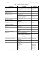

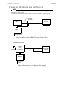


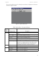


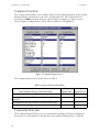
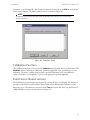
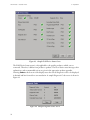


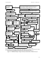

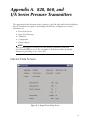


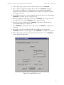

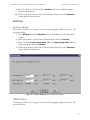
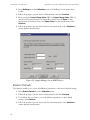

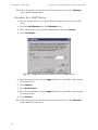
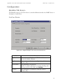

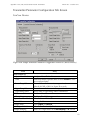


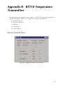
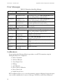


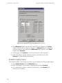


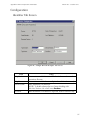


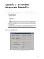

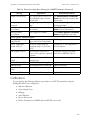


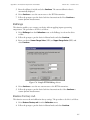

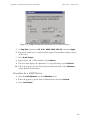
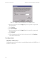
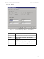
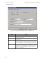


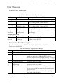


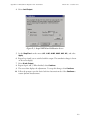
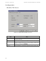


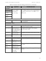


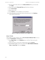
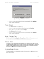


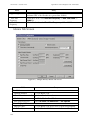
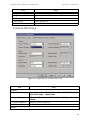

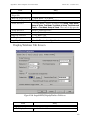
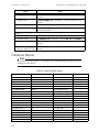


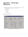
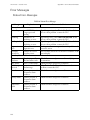
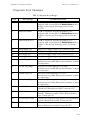
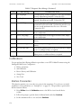

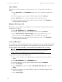
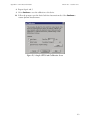
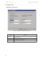
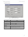


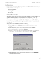


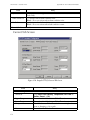
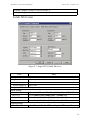
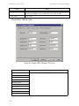
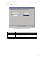


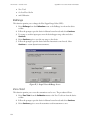


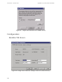

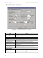


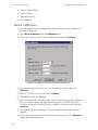

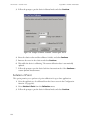
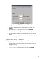


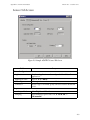
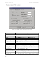
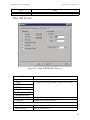

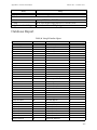


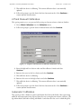
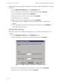


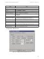


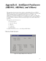

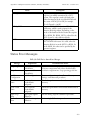

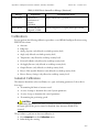
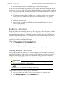


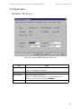
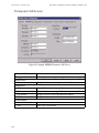
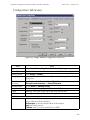
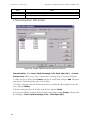
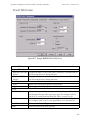


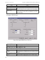
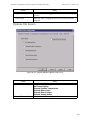
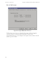
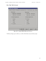


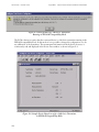
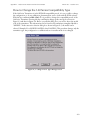

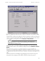
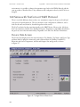

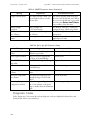

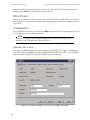

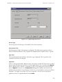


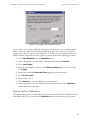


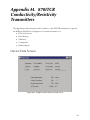
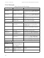
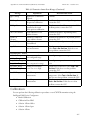


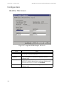


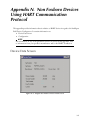
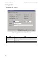
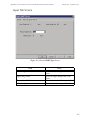
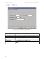


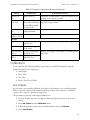
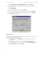
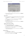


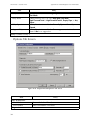


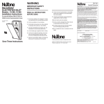

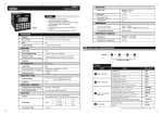
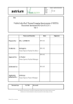

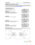
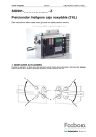


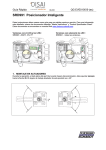


![MI 611-214] PH12 Series pH Sensors and Accessories](http://vs1.manualzilla.com/store/data/006880291_1-d8cfb499f5d4ccda8442b39d1f113a5e-150x150.png)