1
MI 611-211
Instruction
October 2005
870ITPH Intelligent
Electrochemical Transmitter
for pH, ORP, and Ion Selective Electrode Measurements
MI 611-211 – October 2005
Contents
Figures..................................................................................................................................... v
Tables..................................................................................................................................... vi
1. Introduction ......................................................................................................................
Quick Start ...............................................................................................................................
Wiring ..................................................................................................................................
Factory Default Passcode ......................................................................................................
Checking Factory Configuration ..........................................................................................
Verifying Valid Measurements .............................................................................................
Basic Operation in Measure Mode .......................................................................................
Looking for More Information? ............................................................................................
Reference Documents ...............................................................................................................
Specifications ............................................................................................................................
RoHS/WEEE Compliance Statement .......................................................................................
Identification ............................................................................................................................
1
1
1
2
2
2
2
3
3
4
6
6
2. Installation ........................................................................................................................
Unpacking ............................................................................................................................
Mounting .............................................................................................................................
Wiring ..................................................................................................................................
7
7
7
8
3. Operation........................................................................................................................
Controls and Indicators ......................................................................................................
Error Messages ...................................................................................................................
Passcode Access ..................................................................................................................
Viewing and Changing Data ..............................................................................................
Measure ..............................................................................................................................
Diagnostics .........................................................................................................................
Status .................................................................................................................................
Configuration .....................................................................................................................
Hold ..................................................................................................................................
Calibration .........................................................................................................................
11
11
12
13
13
14
15
16
17
29
30
4. Maintenance.................................................................................................................... 35
Appendix A. Structure Diagrams ......................................................................................... 37
Appendix B. Configuration Table ........................................................................................ 49
Index .................................................................................................................................... 55
iii
MI 611-211 – October 2005
iv
Contents
Figures
1
2
3
4
5
6
7
8
9
Wiring .........................................................................................................................
Supply Power vs. Load .................................................................................................
Data Label ....................................................................................................................
Panel Mounting ...........................................................................................................
Surface Mounting ........................................................................................................
Pipe Mounting .............................................................................................................
Wiring .........................................................................................................................
Indicators and Controls ................................................................................................
Example of Structure Diagram .....................................................................................
2
5
6
7
8
8
10
11
14
v
Tables
1
2
3
4
5
6
7
8
9
10
11
12
vi
Product Safety Specifications ........................................................................................
Recommended Conduit and Fittings ...........................................................................
Indicators and Controls ................................................................................................
Diagnostic Error Messages ...........................................................................................
Status Parameters .........................................................................................................
Invensys Foxboro Sensor Data .....................................................................................
American Buffer Tables ................................................................................................
NIST Buffer Tables ......................................................................................................
European Buffer Tables ................................................................................................
List of Characters .........................................................................................................
Sensor Diagnostics .......................................................................................................
Millivolt Supply Formulas ............................................................................................
5
9
11
15
16
20
23
23
25
26
29
33
1. Introduction
The 870ITPH Intelligent Transmitter converts pH, ORP, or Ion Selective Electrode
measurements to a 4 to 20 mA and/or digital output signal depending on the model selected and
the configuration implemented.
The analog only output version (Model 870ITPH-A) supports configuration, calibration, and
diagnostic troubleshooting locally at the front panel. The transmitter has one 4 to 20 mA dc
output which can be software configured (connected) to temperature compensated measurement,
uncompensated (absolute) measurement, or temperature.
The digital output version (Model 870ITPH-F) supports configuration, calibration, and
diagnostic troubleshooting locally at the front panel, via a PC-based configurator anywhere on the
signal leads, or from any I/A Series workstation via an Intelligent Transmitter Fieldbus Module.
The digital output version supports either digital only communication or a hybrid 4 to
20 mA dc/digital communication as configured. When operating in either of these modes, the
transmitter continuously outputs three digital measurement values: temperature compensated
measurement, uncompensated (absolute) measurement, and temperature. In the 4 to 20 mA
mode, you may assign the output to any one of the three measurement parameters.
Quick Start
The purpose of this section is to:
♦
Help you to wire your transmitter
♦
Familiarize you with the instrument configuration as received from the factory
♦
Assist you in verifying that your transmitter is in calibration
♦
Explain normal operation in Measure mode.
Wiring
Your 870IT is a 2-wire transmitter. As such, it transmits output over the same two wires through
which it receives power. If your transmitter was specified with analog communications
(870ITPH-A), you must supply its power source. If it was specified with digital communications
(870ITPH-F), power can be provided via the I/A Series Fieldbus Module. Connect this
power/output signal to the power terminals and the signals from your measurement sensor to the
appropriate terminals near the top of the case as shown in Figure 1.
! WARNING
Wiring installation must comply with any existing local regulations.
! WARNING
A safety agency certified energy barrier must be used with this apparatus to meet
agency certification requirements. See MI 611-206 (FM/CSA) or MI 611-208
(ATEX) for details.
1
5 5A 6
7
8 G
NOT USED
DIAGNOSTIC
REFERENCE ELECTRODE
REF. ELEC. SCREEN (SHLD)
SOLUTION EARTH (GROUND)
MEAS. SCREEN (SHIELD)
2 2A 3 3A 4
SENSOR POWER, +
1
SENSOR POWER, -
4 - 20 mA CAL
+
RTD 3-WIRE
RTD MEASUREMENT
RTD RETURN
–
MEASUREMENT ELECTRODE
1. Introduction
CONFIGURATOR
PC-BASED
MI 611-211 – October 2005
INPUT POWER
CASE EARTH (GROUND)
Figure 1. Wiring
Factory Default Passcode
The factory default passcode for both minor and major passcodes is 0800.
Checking Factory Configuration
Following the structure diagrams in Appendix A and using the arrow keys, you can step through
the product structure as configured in the factory. The factory default values are listed in
Appendix B. There is space provided to make notations in the last column of the table that
comprises this appendix.
Verifying Valid Measurements
Your transmitter was calibrated at the factory. Therefore, you should not have to calibrate it.
However, if you wish to check your calibration, place your sensor in a solution of known value
and, using the Down arrow key, check that the temperature on the second line of the display
agrees with the actual temperature of the solution. Then check the value on the top line of your
display. If the value does not agree with the known value of the solution, recalibrate your
transmitter. The simplest method of doing this is to perform a single point manual calibration
using the solution approach. See “Manual Calibration” on page 31.
Basic Operation in Measure Mode
Measure is the normal operating mode of your transmitter. The pH, ORP, or ISE measurement is
shown on the top line of the display. The second line of your display shows the absolute value of
the sensor signal in millivolts, the output in 4 to 20 mA, or the temperature, depending on your
2
1. Introduction
MI 611-211 – October 2005
configuration. You can view one of the other two selections by using the Up and Down arrow
keys. The display will return to the configured selection when the configured TIMEOUT time is
reached. Configuration errors and transmitter and sensor errors are also shown on your display
while in the Measurement mode.
Looking for More Information?
For more detailed information, refer to the following sections of this manual:
♦
For installation information, refer to “Installation” on page 7.
♦
For detailed explanation of the controls and indicators, refer to “Controls and
Indicators” on page 11.
♦
For detailed configuration instructions, refer to “Configuration” on page 17.
♦
For detailed Calibration instructions, refer to “Calibration” on page 30.
For dimensional information, refer to DP 611-163.
General information on this and other electrochemical products are available on line at
www.foxboro.com (pull down Products menu and select Echem Analytical).
If you need additional help, please call 1-866-746-6477 in the U.S.A. or contact your local
Invensys Foxboro representative.
Reference Documents
Document(a)
DP 611-163
MI 020-495
MI 020-501
MI 020-504
MI 611-206
MI 611-208(b)
PL 611-153
Document Description
Dimensional Print - 870IT Intelligent Transmitters
PC20 Intelligent Field Device Tool
PC50 Intelligent Field Device Tool
PC50 Intelligent Field Device Tool (FoxCom Communication)
FM and CSA Intrinsic Safety Connection Diagrams and
Nonincendive Circuits
Electrochemical Products Safety Information (for European
installations)
Parts List - 870IT Style B Intelligent Transmitters
(a) Documents are available on line at www.foxboro.com (pull down Products menu and select
Documentation).
(b) Available in many languages on line at www.foxboro.com/us/eng/products/
instrumentation/downloads/ecanalyticalsafety/ecanalyticalsafety.htm.
3
MI 611-211 – October 2005
1. Introduction
Specifications
Sensors: Virtually any glass or antimony pH, ISE, or noble metal ORP sensor including the
following:
PH10 DolpHin™ Series pH Sensor
ORP10 DolpHin™ Series ORP Sensor
871A pH/ORP Sensor (see Note)
871PH pH/ORP/ISE Sensor (see Note)
EP459A Fluoride Sensor
EP460 pH/ORP Sensor
EP462 pH Sensor
EP466 pH Sensor
NOTE
871A-2, 871PH-1, and 871PH-2 Sensors, although compatible with 870ITPH
Transmitters, do not supply full sensor diagnostic capability.
Maximum Distance Between Sensor and Transmitter:
With preamplified sensor: 152 m (500 ft)
With non-preamplified sensor that utilizes a driven shield
(PH10-.N, 871A-1, -3; 871PH-5, -6): 15.2 m (50 ft)
Temperature Compensation Inputs:
100 ohm platinum RTD, 2- and 3-wire
1000 ohm platinum RTD, 2- and 3-wire
Balco 3000 ohm RTD
Ambient Temperature: -25 to +55° C
Relative Humidity: 0 to 95% noncondensing
Electromagnetic Compatibility (EMC): The Model 870ITPH Intelligent Transmitter complies
with the requirements of the European EMC Directive 89/336/EEC when the sensor cable and
I/O cables are enclosed in rigid metal conduit. (See Table 2.)
Power Supply Requirements (for 4 to 20 mA output): 12.5 to 42 V dc (see Figure 2)
Load Limitations (for 4 to 20 mA output): 0 to 1450 ohms (see Figure 2)
4
1. Introduction
MI 611-211 – October 2005
1450
1400
TYPICAL SUPPLY VOLTAGE
AND LOAD LIMITS
1400
OUTPUT LOAD, Ω
1300
1200
V dc
Load (ohms)
1100
24
30
32
250 and 565
250 and 860
250 and 960
1000
900
NOTE
The transmitter will function with an output load
less than 250 ohms provided that a PC-based
configurator is not connected to it. Connecting
a PC-based configurator while operating in
this area may cause disturbances and/or
communication problems.
800
700
600
500
OPERATING
OPERATING
AREA
AREA
400
300
250
200
100
0
SEE NOTE
0
20
12.5
30
40 42
SUPPLY VOLTAGE, V dc
Figure 2. Supply Power vs. Load
Product Safety: The 870IT transmitters have been designed to meet electrical safety descriptions
listed in Table 1. For detailed information, or status of testing laboratory approvals/certifications,
contact Invensys Foxboro.
Table 1. Product Safety Specifications
Testing Laboratory,
Type of Protection,
and Area Classification
ATEX intrinsically safe for II 1 G, EEx ia IIC hazardous
locations.
ATEX Type n energy limited for II 3 G EEx nL IIC
hazardous locations
CSA intrinsically safe for Class I, II, and III, Groups A,
B, C, D, E, F, and G, Division 1 hazardous locations.
CSA suitable for use in Class I, II, and III, Groups A, B,
C, D, F, and G, Division 2 hazardous locations.
FM intrinsically safe for Class I, II, and III, Groups A, B,
C, D, E, F, and G, Division 1 hazardous locations.
FM nonincendive for Class I, II, and III, Groups A, B,
C, D, F, and G, Division 2 hazardous locations.
Electrical
Safety Design
Application Conditions
Code
Temperature Class T4 - T6
AAA
Temperature Class T4 - T6
ANN
Connect per MI 611-206.
Temperature Class T4.
Temperature Class T4.
CAA
Connect per MI 611-206.
Temperature Class T4.
Temperature Class T4.
CNZ
FAA
FNZ
5
MI 611-211 – October 2005
1. Introduction
RoHS/WEEE Compliance Statement
This product is exempt from the European Directive 2002/95/EC on the restriction of the use of
certain hazardous substances in electrical and electronic equipment (RoHS), as provided by
Article 2 of that Directive in conjunction with the Product Category #9: “Monitoring and
Control Instruments.”
This product complies with the European Directive 2002/96/EC on Waste Electrical and
Electronic Equipment (WEEE) and is marked accordingly. At end of product life users should
contact Invensys Foxboro for return authorization and shipment instructions.
Identification
A data label is fastened to the left side surface of the enclosure. This label provides the model
number and other information pertinent to your particular transmitter.
MODEL AND STYLE
870ITPH-FWFAA
MODEL
ELECTRICAL CLASSIFICATION CODE
SALES ORDER / SERIAL NUMBER (IF APPLICABLE)
CERT SPEC
REF NO.
ORIGIN
SUPPLY
POWER
FUSE0 - 14 PH
CALIB
FoxCom
CONFIG CD
ALARM
OUTPUT
CUST DATA
PLANT OF MANUFACTURE, DATE, SERIAL NO.
SUPPLY VOLTAGE
POWER CONSUMPTION
MEASUREMENT RANGE
COMMUNICATIONS
OUTPUT
USER INFORMATION
FOXBORO MA USA
Figure 3. Data Label
6
2. Installation
Unpacking
1. Remove the transmitter from the shipping container and check for visible damage.
2. Save the container until you determine that no shipping damage has occurred.
a. If no damage is observed, proceed to the Mounting procedure.
b. If transmitter has been damaged, notify the carrier immediately and request an
inspection report. Obtain a signed copy of the report from the carrier and contact
the Customer Satisfaction Center at 1-866-746-6477 in the U.S.A., or contact
your local Invensys Foxboro representative.
Mounting
Panel Mounting
Panel mounting of the transmitter is shown in Figure 4. For panel cutout size, space requirements,
and other dimensional data, see DP 611-163.
PANEL
TRANSMITTER
BRACKET
NUT
WASHER
Figure 4. Panel Mounting
Surface Mounting
Surface mounting of the transmitter is shown in Figure 5. Fasten mounting bracket to transmitter
using screws, washers, and lockwashers provided. Fasten mounting plate to surface using
appropriate hardware. For space requirements and other dimensional data, see DP 611-163.
7
MI 611-211 – October 2005
2. Installation
LOCKWASHER
TRANSMITTER
BRACKET
SURFACE
CAP SCREW
WASHER
Figure 5. Surface Mounting
Pipe Mounting
Pipe mounting of the transmitter is shown in Figure 6. Securely fasten mounting bracket to a
DN50 or 2-in pipe as shown. For space requirements and other dimensional data, see
DP 611-163.
BRACKET
LOCKWASHER
PIPE
WASHER
CAP SCREW
TRANSMITTER
NUT
U-BOLT
LOCKWASHER
Figure 6. Pipe Mounting
Wiring
Your 870IT is a 2-wire transmitter. As such, it transmits output over the same two wires through
which it receives power. If your transmitter was specified with analog communications
(870ITPH-A), you must supply its power source. If it was specified with digital communications
(870ITPH-F), power can be provided via the I/A Series Fieldbus Module. Connect this
power/output signal and the signal from your measurement sensor as follows:
1. Open the hinged case door.
2. Remove the plastic shipping caps from the openings on the bottom of the case and
replace with proper fittings. You will be running wires through the left and right
openings and capping the middle opening.
8
2. Installation
MI 611-211 – October 2005
! WARNING
Wiring installation must comply with any existing local regulations.
! WARNING
A safety agency certified energy barrier must be used with this apparatus to meet
agency certification requirements. See MI 611-206 (FM/CSA) or MI 611-208
(ATEX) for details.
! CAUTION
1. Failure to adequately seal open ports or secure the cover will jeopardize NEMA 4X,
CSA Enclosure 4X, or IEC IP65 and will void instrument warranty.
2. To maintain a rating of NEMA 4X, CSA Enclosure 4X, or IEC IP65, wiring
methods, conduit, and fittings appropriate to the ratings must be used. Table 2
identifies recommended parts.
! CAUTION
To mimimize RFI/EMI effect, use grounded metal conduit on sensor cable and input
power leads.
Table 2. Recommended Conduit and Fittings
Material
Conduit
Rigid Metal
Semi-Rigid Plastic
1/2 inch Electrical Trade Size
T&B #LTC 050
Semi-Rigid Plastic
Metal Core
Flexible Plastic
Anaconda Type HV, 1/2 inch
T&B #EFC 050
Fitting
T&B* #370
T&B #LT 50P or
T&B #5362
T&B #LT 50P or
T&B #5362
T&B #LT 50P or
T&B #5362
*T&B = Thomas & Betts Corp., 1001 Frontier Road, Bridgewater, NJ 08807
3. Bring the wires from your 2-wire input power in the left opening and connect to the
input power terminals shown in Figure 7. Bring the sensor cable in the right opening
and connect by number to the appropriate terminals near the top of the case per
Figure 7.
4. For non-Foxboro sensors with coax cable, connect RTD to terminals 1 and 2,
measurement electrode to terminal 3, solution ground to terminal 4, and reference
electrode to terminal 5. Solution ground must be wired to a metallic material in
contact with the process solution. If not, jumper terminals 4 and 5.
5. For non-Foxboro sensors with triax cable, connect RTD to terminals 1 and 2,
measurement electrode to terminal 3, measurement screen (shield) to terminal 3A,
solution ground to terminal 4, and reference electrode to terminal 5. Solution ground
9
MI 611-211 – October 2005
2. Installation
must be wired to a metallic material in contact with the process solution. If not,
jumper terminals 4 and 5.
6. If you are not wiring a temperature measuring device, short terminals 1, 2, and 2A to
minimize noise.
POWER
RS-232
IFD MODEM
SUPPLY
(24 V dc)
+
–
IBM COMPATIBLE
OPTIONAL
PC
PRINTER
CABLE
TRANSMITTER
2 2A 3 3A 4
CASE EARTH (GROUND)
Figure 7. Wiring
10
7
8 G
NOT USED
SENSOR POWER, +
REFERENCE ELECTRODE
INPUT POWER
NOTES:
1. IF NOT WIRING A TEMPERATURE MEASURING
DEVICE, SHORT TERMINALS 1, 2, AND 2A.
2. TERMINAL 2A IS NOT USED WHEN YOUR SENSOR
CONTAINS A 2-WIRE TEMPERATURE ELEMENT.
REF. ELEC. SCREEN (SHLD)
5 5A 6
DIAGNOSTIC
1
SENSOR POWER, -
4 - 20 mA CAL
+
SOLUTION EARTH (GROUND)
–
MEAS. SCREEN (SHIELD)
CONFIGURATOR
RTD 3-WIRE
PC-BASED
RTD MEASUREMENT
RTD RETURN
250Ω
MEASUREMENT ELECTRODE
CABLE
3. Operation
Controls and Indicators
Operator controls and indicators are located on the front panel. Figure 8 shows the panel
arrangement. Table 3 identifies the function of each element.
PRIMARY DISPLAY
SECONDARY DISPLAY
WHEN CAL, CONFIG,
STATUS, OR DIAG
20-SEGMENT BARGRAPH
FOR OUTPUT % OF SPAN
WHEN IN MEASURE
MODE
KEY IS PRESSED, TWO
SEGMENTS ONLY APPEAR
UNDER THE APPLICABLE
LEGEND.
7.00 pH
25.0 C
CONFIGURATION KEY
CALIBRATION KEY
ENTER KEY
MEASURE KEY
HOLD KEY
UP, DOWN, LEFT,
AND RIGHT ARROW KEYS
DIAGNOSTIC KEY
STATUS KEY
Figure 8. Indicators and Controls
Table 3. Indicators and Controls
Control/Indicator
Digital Bargraph
Primary Display
Secondary Display
CALibration Key
CONFIGuration Key
HOLD Key
MEASUREment Key
Function
Displays percent-of-range indication.
Displays measurement and some error messages.
Displays the absolute value of the measurement signal in
millivolts, the output in 4 to 20 mA, or the temperature, and error
messages and configuration/calibration prompts.
Places transmitter in Calibration mode. This enables you to calibrate
the transmitter automatically to your buffer solutions or manually to
values entered.
Places transmitter in Configuration mode. This enables you to
configure the value or status of each parameter required for your
application.
Places transmitter in Hold mode. This enables you to hold the
output at a determined value while configuring or calibrating the
transmitter or performing sensor maintenance.
Places transmitter in Measurement (normal operation) mode.
11
MI 611-211 – October 2005
3. Operation
Table 3. Indicators and Controls (Continued)
Control/Indicator
Function
STATUS Key
Places transmitter in Status mode. This enables you to view the
measurement and system parameters and thus assess the
performance of the loop.
DIAGnostics Key
Places transmitter in Diagnostic mode. This enables you to further
identify specific errors and possible solutions to an error flagged in
measurement mode.
Direction (Arrow) Keys Move you through the structure diagram and subsequent menus and
values. They may be used to increment one position at a time, or to
move through a menu or string of values by holding a key in the
depressed position.
ENTER Key
Enters the menu item or value selected.
Error Messages
The 870IT will display one of several messages when a problem occurs. These are summarized
below:
Flashing Display: Occurs when there are not enough significant digits on the display to display a
number. For example, if the PRIMARY SCALE was configured as 99.99 and a measurement of
100 was received, the display would flash +99.99.
CAL ERROR: Occurs when a limit condition was exceeded during an attempted calibration.
CAL appears on the top line and ERROR on the bottom line of the display.
XMTR ER: Occurs in Measure mode only to indicate a transmitter problem. The transmitter is
still configurable but measurements are held at the failsafe value if set.
PROBE ER: Occurs in Measure mode only when one of the following probe errors occurs: Glass,
Lowslope, Coat, Leakage, Preamp, Aging, ATC Short, and ATC Open. For more information, see
“Diagnostics” on page 15. Message appears on the bottom line of the display and flashes
alternately with the bottom line measurement. The transmitter is still configurable. For probe
errors of ATC Short or ATC Open, measurements are held at the temperature default value if set.
CONFIG ER: Occurs in Measure mode only when one of the following configuration errors
occurs: Calibration Required, 4-20 Range, Measurement Range, and Compensation Range. For
more information, see “Diagnostics” on page 15 Message appears on the bottom line of the
display and flashes alternately with the bottom line measurement.
ER DATA: Occurs after you change a value and try to enter it with the ENTER key. Message
appears on the bottom line of the display for 1 to 2 seconds and then automatically returns to the
last legal value. The top line does not change from the previous edit prompt. Situations causing
this message and appropriate responses are:
1. New value is out of range.
2. The slope of a chemical composition curve has changed sign.
3. The first value of a compensation point pair (TEMPx in TEMPCOMP or ABSx in
CHEMCOMP) was entered that was not greater than the last one.
12
3. Operation
MI 611-211 – October 2005
Passcode Access
Two levels of passcode protection are available. The Minor level permits access to Calibration and
Output Hold. The Major level permits changing parameters in Configuration as well as access to
Calibration and Output Hold. Both are 4-digit passcodes. The passcodes may or may not be the
same. They are set as part of configuring the instrument.
Upon entering the Configuration, Calibration, or Hold mode by pressing the appropriate key, the
display will read PASSCODE 0000. Upon entering the proper passcode and then pressing the
ENTER key, the display will change to the next item in the appropriate structure. The initial
factory default value for both Minor and Major passcodes is 0800.
Viewing and Changing Data
In the Configuration, Calibration, Hold, and Status modes, you will need to move through a
structure of parameters (using the arrow keys and ENTER key) to view and/or change the value or
status of a particular parameter. Structure diagrams, located in Appendix A, will aid you in doing
this.
Note that the Up and Down arrow keys will scroll through a menu in either direction. Also, that
the arrow keys may be used to increment one position at a time, or to move continuously through
a menu or string of values by holding the key in the depressed position.
The following example will show you how to use the keys in moving through the structure. The
example used is that of configuring temperature features. For the example, assume Fahrenheit
temperature units, an automatic temperature mode, a default value of 77 ° F, and a 3-wire, 1000
ohm RTD. In following the procedure, refer to Figure 9.
1. Use the Right arrow key to move from CONFIG TEMP to TEMP UNITS and then to
UNITS CELSIUS.
2. Use the Down arrow key to move to UNITS FAHREN and press the ENTER key. This
will enter your Fahrenheit selection and move the display to TEMP MODE. Every
temperature entry in the transmitter will now be in Fahrenheit units.
3. Use the Right arrow key to move to MODE AUTO. Press the ENTER key. This will
enter your Auto selection and move the display to DEFAULT 000.0. The tenths digit
will be flashing.
4. Because you do not need to change the tenths digit, use the Left arrow key to move to
the units digit. Use the Up arrow key to change this digit to 7.
5. Use the Left arrow key to move to the tens digit and the Up arrow key to change this
digit to 7. You have now achieved your goal of setting the value to 77.0, so press the
ENTER key. This will enter your value of 77 and move the display to TEMP TYPE.
6. Use the Right arrow key to move to TYPE RTD and press the ENTER key. This will
enter your selection of RTD and move the display to RTD 2 WIRE.
7. Use the Down arrow key to move to RTD 3 WIRE and press the ENTER key. This
will enter your selection of 3 Wire and move the display to 3 WIRE 100 OHM.
8. Use the Down arrow key to move to 1000 OHM and press the ENTER key. This will
enter your selection of 1000 ohm and move the display back to CONFIG TEMP. This
completes the example.
13
MI 611-211 – October 2005
CONFIG
TEMP
3. Operation
TEMP
UNITS
UNITS
CELSIUS
UNITS
FAHREN
TEMP
MODE
TEMP
TYPE
MODE
AUTO
DEFAULT
MODE
MANUAL
MANUAL
TYPE
RTD
RTD
2 WIRE
2 WIRE
100 OHM
2 WIRE
1000 OHM
RTD
3 WIRE
3 WIRE
100 OHM
3 WIRE
1000 OHM
TYPE
BALCO
Figure 9. Example of Structure Diagram
Measure
Measure is the normal operating mode of your transmitter. The pH, ORP, or ISE measurement is
shown on the top line of the display. Upon returning to Measure mode after changing many
configuration parameters, the display may read CONFIG ER. This typically means that a
calibration is required.
The second line of your display shows the absolute value of the sensor signal in millivolts, the
output in 4 to 20 mA, or the temperature, depending on your configuration. You can view one of
the other two selections by using the arrow keys. The display will return to the configured
selection when the TIMEOUT time is reached. Transmitter (XMTR ER) and sensor (PROBE ER)
errors are also shown on your display while in the Measurement mode.
14
3. Operation
MI 611-211 – October 2005
Diagnostics
(Refer to “Structure Diagram 11” on page 48.)
The Diagnostics mode enables you to perform checks on your system at any point in time. While
you are in the Diagnostic mode, two segments of the bar graph will appear under the legend
DIAG at the top of the front panel. To enter the Diagnostics mode, press the DIAG key on the
front panel. If there are no errors, your display will read DIAGS OK. If there was an error flagged
as XMTR ER, PROBE ER, or CONFIG ER in the Measurement mode, the Diagnostics mode
will help you further identify the specific error and corrective action. Possible errors and the
recommended corrective actions are listed in Table 4.
Table 4. Diagnostic Error Messages
Message
Description
Transmitter Error
Probe Errors
GLASS
Resistance of glass electrode is checked versus solution
ground. Error is flagged if resistance is less than user set
limit.
LOWSLOPE Flags an error after a 2-point calibration in buffers
when the Nernst slope of the sensor becomes less than
the user set limit.
COAT
Checks reference junction resistance against solution
ground. Error is flagged if resistance is greater than user
set limit.
Sensor is not immersed in solution.
LEAKAGE
Checks solution leakage into the probe by checking
resistance between solution ground and the RTD.
Error is flagged if resistance is anything but infinite.
PREAMP
Checks preamplifier by monitoring voltage coming out
of it. Error is flagged at voltage greater than 2 volts.
AGING
Flags an error after a 2-point calibration in pH buffers
when the Nernst slope of the sensor has decreased
sequentially five times.
ATCSHORT Flags an error if the resistance of the temperature
ATC OPEN compensator is greater or less than the expected
resistance of the device configured.
Corrective Action
Replace electrode
Replace electrode or
solution
Clean electrode
Check that solution ground
and reference junction are
immersed in solution.
Replace
Replace
See Note below
Replace temperature
compensator
15
MI 611-211 – October 2005
3. Operation
Table 4. Diagnostic Error Messages (Continued)
Message
Description
Corrective Action
Configuration Errors
CAL REQ
Calibration required
4 - 20 RNG Measurement outside configured range
MEAS RNG Measurement outside configured precision or scale
COMP RNG Measurement outside compensation curve
Calibrate
Reconfigure range or correct
process error
Reconfigure precision or
correct process error
Reconfigure compensation
or correct process error
NOTE
Corrective action for AGING error is to check the value of the slope in the Status
menu. The glass or ISE electrode may be reaching the end of its useful life if the
SLOPE differs greatly from the theoretical value (80% is usual limit but application
requirements should dictate lowest acceptable slope).
Status
(Refer to “Structure Diagram 8” on page 45.)
The Status mode enables you to view the measurement and system parameters and thus assess the
performance of the loop. You may not edit them in this mode. For a string display of more than
eight characters, use the Left and Right arrow keys to scroll the display. All measurements
(outputs) continue while in the Status mode. To enter the Status mode, press the STATUS key.
Move through the menu by using the Up and Down arrow keys. While you are in the Status
mode, two segments of the bar graph will appear under the legend STATUS at the top of your
front panel. The Status menu contains the following parameters.
Table 5. Status Parameters
Parameter
TEMP
SLOPE
ABSOLUTE
mA
GLASSRES
ASYMM
REF RES
ATC RES
CAL NAME
LAST CAL
16
Description
Process Temperature
Efficiency of sensor expressed as the deviation in percent of the slope of the most
recent calibration compared to the standard (e.g., mV/pH/59.16 mV/pH)
Uncompensated millivolt signal from sensor (a)
Analog Output: Analog output value in mA
Digital Output: Output shown on secondary display in mA.
Indicates whether resistance of glass electrode is acceptable
Asymmetry potential (mV difference from the expected theoretical isopotential pH
voltage of zero)
Resistance of reference electrode
Resistance of temperature compensator
Name of last calibrator
Date of last calibration (mm/dd/yy)
3. Operation
MI 611-211 – October 2005
Table 5. Status Parameters (Continued)
Parameter
TAG NUM
TAG NAME
LOCATION
SONUMBER
MS CODE
S/W VER
DEV NAME
DEV TYPE
Description
Tag number
Tag name*
Location of measurement (b)
Sales order number
Model code
Software version
Device name*
Device type*
(a)See Table 12 for expected absolute mV readings. Absolute mV is a very useful sensor troubleshooting tool.
(b)Appears only on devices coded 870ITPH-F.
Configuration
Configuration is the process of enabling functional capability in the transmitter firmware for your
application. This section will enable you to systematically determine and configure the value or
status of each parameter required for your application. Many applications require only changing a
few of the default values already entered. While you are in the Configuration mode, two segments
of the bargraph will appear under the legend CONFIG at the top of your front panel. These
segments will flash if you are also in a Hold mode. To enter the Configuration mode, press the
CONFIG key. At the prompt, enter the four character Major passcode and press ENTER. If the
passcode is correct, the display will flash UNLOCKED and then change to the first item in the
configuration structure, CONFIG DISPLAY. You may then edit any of the parameters in the
Configuration mode. If the passcode is incorrect, the display will flash LOCKED and then change
to the first item in the configuration structure. You may view the parameters in this mode but will
not have the ability to change them. In the UNLOCKED condition, the analog output defaults to
3.8 mA. If you do not want this to happen, turn the HOLD feature on first.
! CAUTION
Always exit the Configuration mode by pressing the Measure key before power is
turned off. This allows proper reinitialization of internal data base security checks.
Config Display
(Refer to “Structure Diagram 1” on page 38.)
This section of the structure enables you under DISPLAY PRIMARY to specify the PRIMARY
SENSOR as pH, ISE, or ORP. This choice configures your analyzer as a pH, ORP or ion selective
electrode transmitter. Only parameters pertinent to the specific measurement technology will
appear in the configuration software after this initial choice is made. If pH, you can further
specify the PRIMARY RESOLUTION as 0.1 or 0.01 pH. If ISE, you can further specify the
PRIMARY SCALE as 9.999, 99.99, 999.9, or 9999 ppm. This choice specifies the largest value
that may be displayed as well as the decimal placement in ppm.
17
MI 611-211 – October 2005
3. Operation
NOTE
A change in the Primary Sensor, Resolution, or Scale requires a calibration.
Next, under DISPLAY SECOND, you can configure the secondary display to show the absolute
value of the measurement in millivolts, the output in 4 to 20 mA, or the temperature.
Config Output
(Refer to “Structure Diagram 1” on page 38.)
This section of the structure first asks you to specify the MODE, referring to the communications
and measurement output. If your transmitter was specified with analog output only (870ITPHA), specify ANALOG. If your transmitter was specified with I/A Series communications
(870ITPH-F), specify ANALOG if you want to have a 600 baud digital signal superimposed over
an analog 4 to 20 mA signal, or specify DIGITAL if you want to have a 4800 baud digital signal
only.
If you configured the mode as ANALOG, you will be asked, under OUTPUT ANALOG, to
specify the 4 to 20 mA output to represent the uncompensated (ABSOLUTE) measurement, the
temperature compensated MEASUREment, or the TEMPerature.
If you configured the mode as DIGITAL, the 4 to 20 mA output will be fixed at 12 mA.
Next, under OUTPUT RANGE, enter the MINimum (4 mA) and MAXimum (20 mA) range
values for the output just specified. Specify between +2000 and -2000 mV for ABSOLUTE, in ° C
or ° F for TEMPerature, or in measurement units (pH for pH, mV for ORP, ppm for ISE) for
MEASURE. To configure the output as reverse acting, enter higher value as MINimum and the
smaller as MAXimum.
NOTE
1. 1. The units for temperature, ° C or ° F, are specified in the section titled “Config
Temp” on page 20.
2. 2. A change in OUTPUT ANALOG will cause the OUTPUT RANGE to default
to 0.0 and thus new MIN and MAX values must be entered.
Lastly, you can specify a fail-safe signal for all transmitter errors and for critical sensor diagnostic
errors. Specify ON to specify a fixed output when in a failed condition. If ON is selected, further
specify the DC mA output between 3.8 and 20.5 mA. The default value is 3.8 mA. If you want to
have this signal outputted with ±0.5 mA pulse (as shown below) for greater visibility on a chart
recorder or data display, specify ON as explained above and then go back and specify PULSE.
The OFF selection is not functional in the current versions of firmware. Any sensor diagnostic
that has been set to ENABLE (see “Config Diags” on page 26) causes the output to go to the failsafe DC mA signal. If sensor diagnostics are enabled, it is important to set the fail-safe DC mA
value to an acceptable safe output level. If you do not want the output to respond to some or all of
the sensor diagnostics, then you must set the selected diagnostics to DISABLE in the Config
Diags menu.
18
3. Operation
MI 611-211 – October 2005
Config Electrod
(Refer to “Structure Diagram 2” on page 39.)
NOTE
This parameter will not appear if ORP was selected as PRIMARY DISPLAY.
This section of the structure asks you to specify the electrode:
♦
If measuring pH: Your choices are GLASS, ANTIMONY, or OTHER. GLASS sets
the isopotential point at 7 pH. ANTIMONY sets it at 1 pH. OTHER allows the
isopotential point to be set manually.
♦
If measuring ISE: You must specify the ion polarity. A positive ion selective
measurement gets more positive (mV-wise) as the concentration increases (e.g., Na+,
K+). A negative ion selective measurement gets more negative (mV-wise) as the
concentration increases (e.g., F–, S–2). For fluoride measurements, this parameter
should be set to negative.
NOTE
A change in the electrode requires a calibration.
Config Tempcomp
(Refer to “Structure Diagram 2” on page 39.)
NOTE
This parameter will not appear if ORP was selected as PRIMARY DISPLAY.
This section of the structure asks you to specify the temperature compensation if you are
measuring pH or ISE.
If measuring pH, specify STANDARD, AMMONIA, or CUSTOM. STANDARD assumes a glass
or antimony electrode and applies the Nernst equation. The nominal temperature compensation
range is -5 to +105 ° C (23 to 221 ° F). AMMONIA compensates for traces of ammonia in addition
to the standard compensation. CUSTOM allows you to specify particular solution characteristics
into the transmitter’s memory. When using this compensation, all measurements will be corrected
back to a reference temperature measurement value. Therefore, you are asked to specify a
reference temperature and a number of points to plot a compensation curve. The reference
temperature (REF TEMP) should be within the nominal temperature compensation range. The
number of points (NUM PTS) can be specified from 2 to 21 points and has a default value of 2.
Each point specifies a value at a certain temperature. The temperatures (TEMPx) should be
within the nominal temperature compensation range. The temperature units are specified in the
next section. The values (VALx) can be specified from -2.00 to +16.00 pH and have a default
of 0.00.
If ISE was chosen as your PRIMARY DISPLAY, you must specify STANDARD or CUSTOM.
CUSTOM causes you to specify a reference temperature and a number of points to plot a
compensation curve. The number of points (NUM PTS) can be specified from 2 to 21 points and
has a default of 2. Each point specifies a value at a certain temperature. The temperature units are
specified in the next section. The values (VALx) can be specified from 0 to 2000 ppm and have a
default of 0.
19
MI 611-211 – October 2005
3. Operation
For CUSTOM compensation, the temperature values must be entered in increasing order and the
slope of the curve cannot change direction. Deviation from this requirement will cause an
ER DATA message and force a resequence through the point pairs.
Config Temp
(Refer to “Structure Diagram 3” on page 40.)
This section of the structure asks you to specify the temperature features. First, specify the TEMP
UNITS as CELSIUS or FAHRENheit. All references to temperature will appear in the specified
units within the transmitter software.
Next, specify the TEMP MODE as AUTO or MANUAL. In the AUTO mode, the temperature
follows the RTD. In MANUAL mode it is set at a fixed value. At this point you can set a
DEFAULT value for the AUTO mode (in case the RTD fails) at the temperature at which you
expect the process to be operating; or you can set a temperature for the MANUAL mode.
Last, specify the TEMP TYPE as standard RTD or BALCO. If you specify the TYPE as RTD,
specify 2-WIRE or 3-WIRE and specify the resistance as 100 OHM or 1000 OHM. Follow Table 6
for Invensys Foxboro sensors.
Table 6. Invensys Foxboro Sensor Data
Sensor
PH10-..1
ORP10-..1
PH10-..2
ORP10-..2
PH10-..3
ORP10-..3
PH10-..4
ORP10-..4
871PH-1
871PH-2
871PH-3
871PH-4
871PH-5
871PH-6
871A-1
871A-2
871A-3
871A-4
EP459A
EP460
EP462
EP466
20
Type
2-wire
Resistance
100 Ω
3-wire
1000 Ω
2-wire
100 Ω
3-wire
1000 Ω
2-wire
2-wire
3-wire
3-wire
2-wire
2-wire
2-wire
2-wire
2-wire
3-wire
2-wire
3-wire
3-wire
3-wire
100 Ω
100 Ω
1000 Ω
1000 Ω
1000 Ω
1000 Ω
100 Ω
100 Ω
1000 Ω
1000 Ω
100 Ω
100 Ω
100 Ω
100 Ω
3. Operation
MI 611-211 – October 2005
Config Damping
(Refer to “Structure Diagram 3” on page 40.)
This section of the structure asks you to specify the damping response time (90% of step).
Choices are 1, 5, 10, 20, 40, and 120 seconds. Damping applies only to measurement data, not to
temperature data.
Config Chemcomp
(Refer to “Structure Diagram 3” on page 40.)
If measuring ISE, this section of the structure asks you to specify the chemical compensation
(CHEMCOMP) as STANDARD or CUSTOM. This is similar to what you did in “Config
Tempcomp” on page 19. CUSTOM causes you to specify a number of points (NUM PTS) to plot
a compensation curve. The number of points can be specified from 2 to 21 and has a default of 2
points. Each point specifies an absolute value (ABSx) and the value you want it to be (NEWx).
The values can be specified from 0 to 2000 ppm and have a default of 0. The decimal point
location for these values was determined as PRIMARY SCALE in CONFIG DISPLAY. The slope
of the curve cannot change direction or be zero between any two points. Deviation from this
requirement will cause an ER DATA message.
Config Instrmnt
(Refer to “Structure Diagram 4” on page 41.)
NOTE
This section is not displayed unless the correct passcode had been entered for
Configuration.
INSTRMNT mA CAL
This subsection allows you to tune the 4 mA and 20 mA values. The procedure is as follows:
1. Connect a digital voltmeter to the to the calibration terminals (see Figure 7).
2. With INSTRMNT mA CAL displayed, press ENTER. The display will change to
mA CAL 4 mA. Press ENTER again.
3. Calibration is performed by having your voltmeter read 100 mV. Do this by selecting
one of the seven icons from the second line of your display by using the Left and
Right arrow keys. When you have highlighted the icon you want, press ENTER. The
icon meanings (shown below) are (from left to right) large increase, medium increase,
small increase, accept and exit, small decrease, medium decrease, large decrease.
4. Repeat Step 3 until your meter reads 100 mV. Then highlight the center icon and
press ENTER. The display will go to mA CAL 20 mA. Press ENTER.
5. Repeat the procedure shown in Steps 3 and 4 for 20 mA. The voltage reading should
be 500 mV.
21
MI 611-211 – October 2005
3. Operation
INSTRMNT STAB IND
When performing a calibration, the transmitter checks for stability in absolute measurement and
temperature before accepting a change. This section enables you to configure the TIME allowed to
attain stability and the amount of fluctuation (VAR) allowed. The value of VAR corresponds to
the least significant digit of the measurement in the PRIMARY DISPLAY you configured in
“Config Display” on page 17. For example, if you configured the PRIMARY RESOLUTION as
0.01 pH, then the value of VAR would be from 0.01 to 0.09 pH expressed as from 1 to 9. Both
TIME and VAR are configured individually in STAB IND MEASurement and
STAB IND TEMPerature.
First, configure STAB IND MEAS as ON or OFF. If you configure this as ON, you need to specify
the TIME between 5 and 60 seconds (in 5-second increments) and the VARiable between 1 and 9.
A longer time period and a smaller measurement value assures more stability during calibration.
The default TIME is 5 seconds and the default VARiable is 9. Thus, if the primary resolution was
0.01 and the default time and variable are used, the values can change at a rate of 0.09 pH over 5
seconds.
Then repeat the procedure for STAB IND TEMP. If you configure this as ON, you need to specify
the TIME between 5 and 60 seconds (in 5-second increments) and the VARiable between 1 and 9
( ° C or ° F). The default TIME is 5 seconds and the default VARiable is 9.
Config Timeout
(Refer to “Structure Diagram 4” on page 41.)
This section of the structure asks you to specify the time in which the instrument will bring you
back to the on-line/Measurement mode from another on-line mode (Status, Diagnostics, or the
view only part of Configuration) when no keyboard input has occurred. In Measure mode,
TIMEOUT also limits the time to view a secondary display other than that configured in CONFIG
DISPLAY. The time may be specified between 0 and 999 seconds. A value of zero (0) disables the
time-out function. The default time is 600 (10 minutes).
Config Buffers
(Refer to “Structure Diagram 5” on page 42.)
NOTE
This parameter will not appear if ISE or ORP was selected as PRIMARY DISPLAY.
This section of the structure asks you to specify the buffers to be used if you are measuring pH
and will use the Automatic Calibration feature described on page 31.
In Automatic Calibration, the pH value calculated with values from the last calibration is used to
decide which buffer is in use. The algorithm checks each buffer starting with Buffer 1 and selects
the first one for which this pH is within 0.5 pH of the average pH for the buffer. You may select
between AMERICAN, NIST, EUROPEAN, and SPECIAL buffers as standard buffer table
choices.
If you select SPECIAL, you must specify the number of points (NUM PTS) between 02 and 11
for Buffer 1, 2, and 3. The default value is 02. Each point specifies a value at a certain
temperature. The temperatures (TEMPx) can be specified from -99.9 to +999.9 ( ° C or ° F) and
22
3. Operation
MI 611-211 – October 2005
have a default of 0.0. The values (VALx) can be specified from -2.00 to +16.00 pH and have a
default of 0.00.
If the average pH values of two special buffers are less than 1 pH unit apart, using this procedure
might result in the wrong buffer being selected. In this case, the buffer selection is based on the
midpoint between the two buffers. It is not necessary to configure all three special buffers. If only
two are used, they should be Buffers 1 and 2. If one is used, it should be Buffer 1. Enter Special
buffer tables in the increasing order of the average pH for the buffer. The average pH is estimated
as (first entry + last entry) / 2.
Tables of buffer values for nominal 4, 7, and 10 pH for American, NIST, and European buffers
are listed below:
Table 7. American Buffer Tables
Temperature
°C
4.00 pH
7.00 pH
10.01 pH
pH Value
pH Value
pH Value
0
5
10
15
20
25
30
35
40
45
50
4.00
4.00
4.00
4.00
4.00
4.00
4.01
4.02
4.03
4.04
4.06
7.12
7.09
7.06
7.04
7.02
7.00
6.99
6.99
6.98
6.98
6.97
10.32
10.25
10.18
10.12
10.06
10.01
9.97
9.93
9.89
9.86
9.83
NOTE
Values in Table 7 are based on common (nominal value) technical buffer systems.
pH values are at 25°C. Chemical formulas are as follows:
4.00 pH: 0.05 molar Potassium Hydrogen Phthalate
7.00 pH: 0.041 molar Disodium Hydrogen Phosphate;
0.026 molar Potassium Dihydrogen Phosphate
10.01 pH: 0.025 molar Sodium Carbonate;
0.025 molar Sodium Bicarbonate
Table 8. NIST Buffer Tables
Temperature
°C
4.01 pH
6.86 pH
9.18 pH
pH Value
pH Value
pH Value
0
5
10
4.00
4.00
4.00
6.98
6.95
6.92
9.46
9.40
9.33
23
MI 611-211 – October 2005
3. Operation
Table 8. NIST Buffer Tables (Continued)
Temperature
°C
4.01 pH
6.86 pH
9.18 pH
pH Value
pH Value
pH Value
15
20
25
30
35
40
45
50
4.00
4.00
4.01
4.02
4.03
4.04
4.05
4.06
6.90
6.88
6.86
6.85
6.84
6.84
6.83
6.83
9.28
9.23
9.18
9.14
9.10
9.07
9.04
9.01
NOTE
Values in Table 8 are based on NIST Primary Buffer Systems. pH values are at
25°C. Chemical formulas are as follows:
4.01 pH: 0.05 molar Potassium Hydrogen Phthalate
6.86 pH: 0.025 molar Potassium Dihydrogen Phosphate;
0.025 molar Disodium Hydrogen Phosphate
9.18 pH: 0.01 molar Sodium Tetraborate Decahydrate (Borax)
24
3. Operation
MI 611-211 – October 2005
Table 9. European Buffer Tables
Temperature
°C
0
5
10
15
20
25
30
35
40
45
50
55
60
70
80
90
95
4.61 pH
7.00 pH
9.21 pH
pH Value
pH Value
pH Value
7.12
7.09
7.06
7.04
7.02
7.00
6.99
6.98
6.97
6.97
6.97
6.97
6.98
7.00
7.04
7.09
7.12
9.52
9.45
9.38
9.32
9.26
9.21
9.16
9.11
9.07
9.03
8.99
8.96
8.93
8.88
8.83
8.79
8.77
4.64
4.62
4.61
4.61
4.61
4.62
4.63
4.64
4.66
4.67
4.69
4.71
NOTE
Values in Table 9 are based on commercially available technical buffers used in some
parts of Europe. pH values are at 25°C. Chemical formulas are as follows:
4.61 pH: 0.1 molar Sodium Acetate; 0.1 molar Acetic Acid
7.00 pH: 0.026 molar Potassium Dihydrogen Phosphate;
0.041 molar Disodium Hydrogen Phosphate
9.21 pH: 0.05 molar Sodium Tetraborate Decahydrate (Borax)
Config Passcode
(Refer to “Structure Diagram 5” on page 42.)
NOTE
This parameter is not displayed if the transmitter is locked (i.e., the correct passcode
was not entered for Configuration).
This section of the structure asks you to specify the Minor and Major Passcode. The Minor
passcode limits access to routine maintenance functions including CALIBRATION and output
HOLD. The Major passcode prohibits unauthorized personnel from changing the configuration
parameters. Each is a 4-character string between 0000 and 9999. They may or may not be the
25
MI 611-211 – October 2005
3. Operation
same. The default passcodes are both 0800. To disable the passcode feature configure a passcode
as 0000.
Config Strings
(Refer to “Structure Diagram 5” on page 42.)
This section of the structure asks you to specify the designation of the Tag Number (TAG NUM),
Tag Name (TAG NAME), Location (LOCATE), and Device Name (DEV NAME). Each can be
made up of characters from Table 10 and can be of up to the following number of characters in
length:
TAG NUM
TAG NAME
LOCATE
DEV NAME
12
14
14
6
Only eight characters will be shown on your display at a time but the display will scroll as
you enter additional characters.
NOTE
Only TAG NUM appears if your transmitter was specified with analog output only
(870ITPH-A).
Table 10. List of Characters
Characters
0 through 9
. (period)
–(dash)
(blank)
A through Z
_ (underscore)
Config AC Power
(Refer to “Structure Diagram 6” on page 43.)
This section of the structure asks you to specify, under AC PWR, the frequency that is used in
your location. This information is used to eliminate interference in the DIAGnostic mode. If you
specify 50 Hz, the transmitter performs its diagnostic tests using 60 Hz. If you specify 60 Hz, the
diagnostics uses 50 Hz.
Config Diags
(Refer to “Structure Diagram 6” on page 43.)
This section of the structure allows configuring error messages that can appear on your display.
You can elect to ENABLE all messages, DISABLE all messages or enable or disable each of the
26
3. Operation
MI 611-211 – October 2005
following individually: GLASS, LEAKAGE, LOWSLOPE, PREAMP, ATCSHORT, ATC
OPEN, COAT, AGING, 4-20 RNG, COMP RNG, and MEAS RNG. Each of these is discussed
below. A typical approach is to initially select ENABLE ALLDIAGS and to DISABLE select messages later when you find out that you do not require them. Further, when you have messages on
your display, you may CLEAR all of the messages or CLEAR specific messages. This feature then
disables the reporting of those messages for an hour to allow time for corrective maintenance.
NOTE
Any sensor diagnostic that has been set to ENABLE causes the output to go to the
fail-safe DC mA value when the diagnostic condition exists. Therefore, if sensor
diagnostics are enabled, it is important to set the fail-safe DC mA value to an
acceptable safe output level (see “Config Output” on page 18). If you do not want the
output to respond to some or all of the sensor diagnostics, then you must set the
selected diagnostics to DISABLE.
GLASS
This message reports a problem in the resistance of a glass electrode in the probe. Resistance of a
glass electrode is checked versus solution ground. An error message appears if the resistance is less
than user set limit. Besides clearing, enabling, and disabling the message, you can LIMIT the
message to resistances below a set value. The LIMIT value may be set between 0 and 1100 kΩ in
increments of 100 kΩ. The default value is 500 kΩ. You may also specify a CUTOFF Temperature
above which this feature is disabled. CUTOFF T can be set between 0 and 100 ( ° C or ° F). The
default value is 50. The resistance of a glass bulb decreases (roughly is halved) for every 10°C
increase in temperature.
NOTE
Disable this message for ORP and ISE measurement.
LEAKAGE
This message reports a problem of liquid leakage into the sensor. The diagnostics checks the
resistance between solution ground and the RTD. An error message appears if the resistance is
anything but infinite. The message may be enabled, disabled, or cleared.
LOWSLOPE
This message reports a problem usually associated with an aging glass electrode. An error message
appears after a 2-point calibration in buffer solutions when the Nernst slope of the sensor
becomes less than the user set limit. The limit may be set between 0 and 100 percent. The default
value is 80. The message may be enabled, disabled, or cleared.
NOTE
Disable this message for ORP and ISE measurement.
PREAMP
This message reports a failed preamplifier. The diagnostics checks the preamplifier by monitoring
the voltage coming out of it. An error message appears when the voltage is greater than 2 volts.
27
MI 611-211 – October 2005
3. Operation
The message may be enabled, disabled, or cleared. The following Foxboro sensors contain a
preamplifier: 871A-4, 871PH-3, 871PH-4, PH10-.P and ORP10-.P.
ATCSHORT, ATC OPEN
This message reports a problem if the resistance of the temperature compensator is greater or less
than the expected resistance of the device configured. The message for each may be enabled,
disabled, or cleared.
COAT
This message reports an increase in reference junction resistance. This can result from a fouled
reference junction or if the electrode is not immersed in the process solution. The diagnostic
checks the resistance against solution ground. An error message appears if the resistance is greater
than the user set limit. The limit may be set between 0 and 100 kΩ in increments of 10 kΩ. The
default value is 80. The message may be enabled, disabled, or cleared.
NOTE
1. During normal operation, this diagnostic may indicate that the pipe or tank has
gone dry and the sensor is no longer in solution.
2. During sensor maintenance such as cleaning or calibration, this diagnostic may
appear during the times the sensor is out of solution. When the sensor is again
immersed, the diagnostic should turn itself off in a few minutes. If the diagnostic
remains on, then the sensor should be treated as having a coating.
AGING
This message reports an aging glass electrode. An error message appears after a 2-point calibration
in pH buffer solutions when the Nernst slope of the sensor has decreased sequentially five times.
The message may be enabled, disabled, or cleared.
4-20 RNG
This message reports that the measurement that is tied to the analog output is outside the range
that is configured for the application. The message may be enabled, disabled, or cleared.
COMP RNG
This message reports that the measured temperature or the absolute measurement is outside the
temperature or chemical compensation curve that is configured for the application. The message
may be enabled, disabled, or cleared.
MEAS RNG
This message reports that the measurement cannot be displayed accurately in the precision/scale
that is configured for the application. The message may be enabled, disabled, or cleared.
Table 11 shows what diagnostics are available with various Foxboro sensors if enabled and
configured with reasonable limits.
28
3. Operation
MI 611-211 – October 2005
Table 11. Sensor Diagnostics
Diagnostic(a)
Sensor
Glass
Leakage
Lowslope
Preamp
Coat
Aging
ATC
PH10
ORP10
871PH-1
871PH-2
871PH-3
871PH-4
871PH-5
871PH-6
871A-1
871A-2
871A-3
871A-4
EP460-.N
EP460-.P
EP462
EP466
X
X
X
X
X
X
X
X (b)
X (b)
X
X
X
X
X
X
X
X
X
X
X
X
X
X
X
X
X
X
X
X
X
X
X
X
X
X
X
X
X
X
X
X
X
X
X
X
X
X
X
X
X
X
X
X
X
X
X
X
X
X
X
X
X
X
X
X
X
X
X
X
X
X
X
X
(a)X = applicable; blank = not applicable
(b)For PH10-.P or ORP10-.P.
Hold
(Refer to “Structure Diagram 7” on page 44.)
The Hold mode enables you to hold the output at a determined value, thus allowing you to
configure or calibrate the transmitter or perform sensor maintenance without disturbing the
control loop. If you do not put the transmitter in Hold mode before configuring or calibrating,
the output will go to 4 mA if you have configured the output as ANALOG or it will be held at the
present value if you have configured the output as DIGITAL.
While you are in the Hold mode, the bar graph will flash on and off. To enter the Hold mode,
press the HOLD key. You will be prompted to enter the Minor Passcode. If you enter the incorrect
passcode, the transmitter will revert to the Measurement (normal) mode. If you enter the correct
passcode, the display will read HOLD OFF or HOLD ON. If it reads HOLD OFF, use the Down
arrow key to change it to HOLD ON. Then specify whether you want to hold the output at the
PRESENT value or at another value that you will MANUALly set.
If you selected MANUAL and your transmitter was specified with analog communications
(870ITPH-A), your display will read MANUAL ANALOG. Specify the value between 4.00 and
20.00 mA at which you want to hold the output while in the Hold mode. The default value is
4.00.
29
MI 611-211 – October 2005
3. Operation
If you selected MANUAL and your transmitter was specified with digital communications
(870ITPH-F), and you had previously selected ANALOG under CONFIG OUTPUT, your display
will read MANUAL ANALOG.
1. Specify the value between 4.00 and 20.00 mA at which you want to hold the output
while in the Hold mode. The default value is 4.00.
2. Next, go to MANUAL DIGITAL and specify the MEASUREment units,
TEMPerature, and ABSOLUTE value at which you want to hold the output while in
the Hold mode.
a. The TEMPerature can be specified between -99.9 and +999.9 ( ° C or ° F). The
default value is 0.0.
b. The ABSOLUTE value can be specified between -2000.0 and +2000.0 mV. The
default value is 0.0.
If you selected MANUAL and your transmitter was specified with digital communications
(870ITPH-F), and you had previously selected DIGITAL under CONFIG OUTPUT, your display
will prompt you to specify the MEASUREment units, TEMPerature, and ABSOLUTE value at
which you want to hold the output while in the Hold mode.
1. The TEMPerature can be specified between -99.9 and +999.9 ( ° C or ° F). The default
value is 0.0.
2. The ABSOLUTE value can be specified between -2000.0 and +2000.0 mV. The
default value is 0.0.
Calibration
(Refer to “Structure Diagram 9” on page 46 and “Structure Diagram 10” on page 47.)
Calibration routines in your transmitter were designed for simplicity and the elimination of user
errors. The procedures are self-prompting. Two routines are available if you are measuring pH. A
manual calibration enables you to enter or edit the value(s) of your solution. A single point or a
2-point manual calibration may be performed. However, a single point calibration may only be
used if you have previously done a 2-point calibration with your sensor. An automatic calibration
provides a buffer-recognition mechanism which locks in on the buffer value most closely
representing the combination of millivolts and temperature values being reported from the sensor.
Only manual calibration is available if you are measuring ORP or ISE. Only single point
calibration is available if you are measuring ORP. Note that damping is not performed during
either manual or automatic calibration.
NOTE
Before doing any calibration, check that the temperature on the secondary display
in the Measure mode agrees with the actual temperature of the solution. If there is a
difference, the actual temperature should be entered under CAL TEMP in the
Calibration mode before beginning your calibration. The temperature may be
between -99.9 and + 999.9 ( ° C or ° F).
While you are in the Calibration mode, two segments of the bar graph will appear under the
legend CAL at the top of your front panel. These segments will flash if you are also in a Hold
mode. To enter the Calibration mode, press the CAL key. You will be prompted to enter the
Minor passcode. If you enter the incorrect passcode, the transmitter will revert to the
30
3. Operation
MI 611-211 – October 2005
Measurement (normal) mode. If you enter the correct passcode, the display will read
CAL MANUAL. If you need to adjust the temperature per the note above, go to CAL TEMP in
the structure and enter the correct value. Then go back to either CAL MANUAL or to
CAL AUTO.
If you are measuring ORP, instead of a MANUAL SINGLEPT calibration, you can use a
MANUAL ABSOLUTE calibration. This is an internal calibration that rids the transmitter of
nonapplicable calibration data. To do this, go from MANUAL ABSOLUTE to
PERFORM ABSOLUTE and press ENTER.
If your diagnostics were configured to enable a COAT message, this message appears if the sensor
is out of the solution for a sufficient period of time. This is a normal occurrence. The message
disappears when you immerse your sensor.
NOTE
Accurate calibration requires that the sensor and the standard solution must be
stable at the same temperature. A less than optimum calibration results if either the
sensor or the solution is changing temperature during the calibration procedure. For
example, when a sensor is removed from a hot process, the sensor takes several
minutes to cool to ambient temperature. Calibration should not be performed until
the sensor has reached a stable temperature. You can monitor the temperature of the
sensor in Status mode.
Manual Calibration
To perform a manual calibration (grab calibration):
1. Specify SINGLEPT or TWO PT calibration. SINGLEPT must be used for ORP.
2. Immerse your sensor in Solution 1 and press ENTER. If stability parameters were
configured ON, the display READING XXXXXXXX will flash until stability is
achieved and then alternate with the message ENTER TO EDIT. Wait for this message
and then press ENTER again. If stability parameters were configured OFF, watch for
the measurement to stabilize before proceeding to press ENTER.
3. If the reading is not correct, edit it to the correct value under VALUE 1. Press ENTER.
Wait for a display of CAL COMPLETE (for SINGLEPT) or IMMERSE IN SOL 2
(for TWO PT). If calibration was not successfully completed, the display will read
CAL ERROR and return you to MANUAL SINGLEPT or MANUAL TWO PT.
4. If you are doing a 2-point calibration, place the sensor in the second solution and
repeat the procedure. Upon completion a display of CAL COMPLETE will appear.
5. Press MEASURE to return to Measurement mode.
NOTE
A manual calibration of the transmitter without its sensor can also be done with
theoretical millivolt inputs. See “Electronic Calibration” below.
Automatic Calibration
In Automatic Calibration, the pH value is first measured with the last calibration constants
entered to decide which buffer is in use. The algorithm checks each buffer starting with Buffer 1
31
MI 611-211 – October 2005
3. Operation
and selects the first one for which this pH is within 0.5 pH of the average pH for the buffer. If this
pH is not within 0.5 pH unit of any buffer table, a CAL ERROR message is displayed and no
buffer is selected.
To perform an automatic calibration:
1. Press ENTER at the prompt CAL AUTO.
2. At the prompt IMMERSE IN BUF 1, immerse your sensor in the first buffer solution
and press ENTER after you have done so.
3. If stability parameters were configured ON, the display READING XX.XX pH will
flash until stability is achieved and then alternate with the message ENTER TO
CONTINUE. Wait for this message and then press ENTER again. If stability
parameters were configured OFF, watch for the measurement to stabilize before
proceeding to press ENTER. The instrument will then find the nearest buffer value
and display that value on the display under the heading BUF 1 IS. Press ENTER if
acceptable.
4. Wait for the first calibration to be completed. At the prompt IMMERSE IN BUF 2,
immerse your sensor in the second solution and repeat the procedure just completed
for BUF 1. Completion will be indicated with the display CAL COMPLETE.
Documentation of Calibration Procedure
Next, optionally follow the prompts to enter the calibration date, and name of the calibrator. The
date should be in the form mm/dd/yy. The name of the calibrator can contain up to six
characters.
NOTE
Invensys Foxboro recommends keeping a record of your calibrations. Recording the
mV values and slope can help you establish maintenance and replacement
information on your sensors. See Table 12 to calculate the expected mV value
generated by a sensor in contact with a buffer of known pH value. Slope and mV
values together provide useful data for troubleshooting the pH sensor.
Electronic Calibration
This calibration procedure can be used to verify the calibration of the transmitter. It is not
required at startup or for routine sensor/transmitter loop calibration. This procedure is
recommended for troubleshooting a measurement loop to isolate a problem to the transmitter or
eliminate the transmitter as a source of a problem. A millivolt source is used to supply theoretical
millivolt inputs in place of the sensor.
1. Disconnect all sensor leads from your transmitter.
2. Connect a millivolt source between sensor input terminals as follows: positive to
terminal 3 and negative to terminal 4. Jumper terminals 4 and 5.
3. In Configuration mode, go to CONFIG TEMP and set the temperature in MANUAL
to 25 ° C or 77 ° F.
4. Go to Calibration mode. In CAL MANUAL, specify SINGLEPT or TWO PT
calibration. SINGLEPT must be used for ORP.
32
3. Operation
MI 611-211 – October 2005
5. Adjust the millivolt supply to your first value as determined by the formula in
Table 12 and press ENTER. Wait for the display READING XXXXXXXX to alternate
with the message ENTER TO EDIT and then press ENTER again.
Table 12. Millivolt Supply Formulas
Measurement
Mode
mV Power Supply
Formula
Glass pH
(pH-7)x (-59.16)
Antimony pH
(pH-1)x (-55)
ORP
ISE
(mV)
-59 x log (expected Fin ppm) + 118 mV
Examples
pH0: (0-7) x (-59.16) = +414.1 mV
pH14: (14-7) x (-59.16) = -414.1 mV
pH0: (0-1) x (-55.00) = +55.0 mV
pH7: (7-1) x (-55.00) = -330.0 mV
Input absolute millivolt
Fluoride (F-)
Charge is negative and monovalent (n=-1)
Typical mV values:
1 ppm: (-59)log(1) +118 = 118 mV
2 ppm: (-59)log(2) +118 = 100 mV
10 ppm: (-59)log(10) = 118 = 59 mV
100 ppm: (-59)log(100) +118 = 0 mV
6. If the reading is not correct, enter the correct value under VALUE 1. Press ENTER.
Wait for a display of CAL COMPLETE (for SINGLEPT) or IMMERSE IN SOL 2
(for TWO PT). If calibration was not successfully completed, The display will read
CAL ERROR and return you to MANUAL SINGLEPT or MANUAL TWO PT.
7. If you are doing a 2-point calibration, adjust the millivolt supply to the second value
and repeat the procedure.
8. Go to Measure mode. Adjust the millivolt source to a known value between the
calibration points and verify the measurement as displayed on the transmitter per
Table 12.
9. Go to Configuration mode to reset the temperature to AUTO or desired MANUAL
setting as necessary.
10. Lastly, reconnect your sensor wires to the transmitter.
33
MI 611-211 – October 2005
34
3. Operation
4. Maintenance
! WARNING
This product contains components that have critical safety characteristics. Do not
substitute components. Replace components only with identical factory supplied
components. Component substitution may impair the electrical safety of this
equipment and its suitability for use in hazardous locations.
The maintenance of the 870IT Transmitter is limited to replacement of the keypad, the core
printed wiring assembly (PWA), and the sensor PWA. See PL 611-156 for Style A or PL 611-153
for Style B transmitter part numbers. Attempts to repair printed wiring assemblies could result in
damage and voiding of the warranty. The recommended repair procedure is replacement of the
PWA or return of the PWA to the factory for repair.
35
MI 611-211 – October 2005
36
4. Maintenance
Appendix A. Structure Diagrams
Top Level Structure Diagram
CONFIG
DISPLAY
CONFIG
OUTPUT
CONFIG
ELECTROD
CONFIG
TEMPCOMP
CONFIG
TEMP
CONFIG
DAMPING
CONFIG
CHEMCOMP
CONFIG
INSTRMNT
CONFIG
TIMEOUT
CONFIG
BUFFERS
CONFIG
PASSCODE
CONFIG
STRINGS
CONFIG
AC PWR
CONFIG
DIAGS
37
MI 611-211 – October 2005
Appendix A. Structure Diagrams
Structure Diagram 1
CONFIGURATION
If PASSCODE MAJOR ≠ 0000
PASSCODE
CONFIG
DISPLAY
DISPLAY
PRIMARY
PRIMARY
SENSOR
SENSOR
pH
ISE
ORP
If pH
PRIMARY
RESOLUTN
RESOLUTN
0.1 pH
0.01 pH
If ISE
PRIMARY
SCALE
SCALE
9.999 ppm
99.99 ppm
999.9 ppm
9999. ppm
DISPLAY
SECOND
SECOND
TEMP
ABSOLUTE
mA
CONFIG
OUTPUT
MODE
OUTPUT
ANALOG
DIGITAL
ANALOG
ANALOG
ABSOLUTE
MEASURE
TEMP
OUTPUT
RANGE
MIN
OUTPUT
FAIL SIG
FAIL SIG
OFF
ON
PULSE
CONFIG ELECTROD
(see next page)
38
MAX
DC mA
Appendix A. Structure Diagrams
MI 611-211 – October 2005
Structure Diagram 2
CONFIGURATION (cont.)
CONFIG OUTPUT
(see previous page)
CONFIG
ELECTROD
ELECTROD
If pH
GLASS
ANTIMONY
OTHER
ISO POT
If ISE
POSITIVE
NEGATIVE
CONFIG
TEMPCOMP
TEMPCOMP
If pH
STANDARD
AMMONIA
CUSTOM
REF TEMP
NUM PTS
TEMPx
VALx
TEMPx
VALx
If ISE
STANDARD
CUSTOM
REF TEMP
NUM PTS
TEMPx
VALx
TEMPx
VALx
CONFIG TEMP
(see next page)
39
MI 611-211 – October 2005
Appendix A. Structure Diagrams
Structure Diagram 3
CONFIGURATION (cont.)
CONFIG TEMPCOMP
(see previous page)
CONFIG
TEMP
TEMP
UNITS
UNITS
CELSIUS
FAHREN
TEMP
MODE
MODE
AUTO
MANUAL
TEMP
TYPE
DEFAULT
MANUAL
TYPE
RTD
BALCO
RTD
2 WIRE
2 WIRE
100 OHM
1000 OHM
3 WIRE
3 WIRE
100 OHM
1000 OHM
CONFIG
DAMPING
DAMPING
1 SEC
5 SEC
10 SEC
20 SEC
40 SEC
120 SEC
If ISE
CONFIG
CHEMCOMP
CHEMCOMP
STANDARD
CUSTOM
CONFIG INSTRMNT
(see next page)
40
NUM PTS
ABSx
NEWx
ABSx+1
NEWx+1
Appendix A. Structure Diagrams
MI 611-211 – October 2005
Structure Diagram 4
CONFIGURATION (cont.)
CONFIG CHEMCOMP
(see previous page)
If ANALOG
CONFIG
INSTRMNT
INSTRMNT
mA CAL
INSTRMNT
STAB IND
mA CAL
4 mA
4 mA
mA CAL
20 mA
20 mA
STAB IND
MEAS
MEAS
OFF
ON
STAB IND
TEMP
TIME
ON
VAR
VAR
ON
TIME
TIME
ON
VAR
VAR
TEMP
OFF
ON
CONFIG
TIMEOUT
ON
TIME
TIMEOUT
CONFIG BUFFERS
(see next page)
41
MI 611-211 – October 2005
Appendix A. Structure Diagrams
Structure Diagram 5
CONFIGURATION (cont.)
CONFIG TIMEOUT
(see previous page)
If pH
CONFIG
BUFFERS
BUFFERS
AMERICAN
NIST
EUROPEAN
SPECIAL
SPECIAL
BUFFER 1
SPECIAL
BUFFER 2
SPECIAL
BUFFER 3
CONFIG
PASSCODE
CONFIG
STRINGS
CONFIG ac PWR
(see next page)
42
PASSCODE
MINOR
MINOR
PASSCODE
MAJOR
MAJOR
STRINGS
TAG NUM
TAG NUM
STRINGS
TAG NAME
TAG NAME
STRINGS
LOCATE
LOCATE
STRINGS
DEV NAME
DEV NAME
NUM PTS
NUM PTS
NUM PTS
TEMPx
VALx
TEMPx+1
VALx+1
TEMPx
VALx
TEMPx+1
VALx+1
TEMPx
VALx
TEMPx+1
VALx+1
Only on 870ITPH-F Transmitters
Appendix A. Structure Diagrams
MI 611-211 – October 2005
Structure Diagram 6
CONFIGURATION (cont.)
CONFIG STRINGS
(see previous page)
CONFIG
AC PWR
AC PWR
60 Hz
50 Hz
CONFIG
DIAGS
DIAGS
ALLDIAGS
ALLDIAGS
CLEAR
ENABLE
DISABLE
DIAGS
GLASS
GLASS
CLEAR
ENABLE
DISABLE
LIMIT
CUTOFF T
DIAGS
LEAKAGE
LIMIT
CUTOFF T
LEAKAGE
CLEAR
ENABLE
DISABLE
DIAGS
LOWSLOPE
LOWSLOPE
CLEAR
ENABLE
DISABLE
LIMIT
DIAGS
PREAMP
LIMIT
PREAMP
DIAGS
AGING
CLEAR
ENABLE
DISABLE
DIAGS
ATCSHORT
CLEAR
ENABLE
DISABLE
ATCSHORT
DIAGS
4 - 20 RNG
CLEAR
ENABLE
DISABLE
DIAGS
ATC OPEN
ATC OPEN
DIAGS
COMP RNG
Continued
COMP RNG
CLEAR
ENABLE
DISABLE
COAT
CLEAR
ENABLE
DISABLE
LIMIT
4 - 20 RNG
CLEAR
ENABLE
DISABLE
CLEAR
ENABLE
DISABLE
DIAGS
COAT
AGING
DIAGS
MEAS RNG
LIMIT
MEAS RNG
CLEAR
ENABLE
DISABLE
43
MI 611-211 – October 2005
Appendix A. Structure Diagrams
Structure Diagram 7
HOLD
If PASSCODE MINOR ≠ 0000
PASSCODE
HOLD
OFF
HOLD
ON
ON
PRESENT
MANUAL
If ANALOG MODE
MANUAL
ANALOG
ANALOG
MANUAL
DIGITAL
DIGITAL
MEASURE
MEASURE
DIGITAL
TEMP
TEMP
DIGITAL
ABSOLUTE
ABSOLUTE
If DIGITAL MODE
44
MANUAL
MEASURE
MEASURE
MANUAL
TEMP
TEMP
MANUAL
ABSOLUTE
ABSOLUTE
Appendix A. Structure Diagrams
MI 611-211 – October 2005
Structure Diagram 8
STATUS
TEMP
SLOPE
ABSOLUTE
mA
GLASSRES
ASYMM
REF RES
ATC RES
CAL NAME
LAST CAL
TAG NAME*
LOCATION*
SONUMBER
MS CODE
S/W VER
DEV NAME*
DEV TYPE*
TAG NUM
* Appears only on devices coded 870ITPH-F
45
MI 611-211 – October 2005
Appendix A. Structure Diagrams
Structure Diagram 9
CALIBRATION
If PASSCODE MINOR ≠ 0000
PASSCODE
If pH
CAL
MANUAL
MANUAL
SINGLEPT
MANUAL
TWO PT
IMMERSE
IN SOL
If error during calibration
IMMERSE
IN SOL 1
READING
XXXXXXX
IMMERSE
IN SOL 2
CAL
ERROR
IMMERSE
IN BUF 1
ENTER TO
EDIT
CAL
ERROR
CAL
ERROR
CAL
AUTO
READING
XXXXXXX
READING
xx.xx pH
VALUE 1
CAL
COMPLETE
ENTER TO
EDIT
VALUE 1
If error during calibration
READING
XXXXXXX
ENTER TO
EDIT
VALUE 2
If error during calibration
CAL
COMPLETE
ENTER TO
CONTINUE
BUF 1 IS
xx.xx pH
BUF NOT
FOUND
CAL
ERROR
IMMERSE
IN BUF 2
If error during calibration
READING
xx.xx pH
ENTER TO
CONTINUE
BUF NOT
FOUND
CAL
ERROR
CAL
TEMP
TEMP
CAL
DATE
DATE
CAL
PERSON
(If ISE)
46
PERSON
If error during calibration
BUF 2 IS
xx.xx pH
CAL
COMPLETE
Appendix A. Structure Diagrams
MI 611-211 – October 2005
Structure Diagram 10
CALIBRATION (cont.)
If ISE
CAL
MANUAL
MANUAL
SINGLEPT
MANUAL
TWO PT
IMMERSE
IN SOL
If error during calibration
IMMERSE
IN SOL 1
READING
XXXXXXX
IMMERSE
IN SOL 2
CAL
ERROR
TEMP
CAL
DATE
DATE
CAL
PERSON
ENTER TO
EDIT
CAL
ERROR
CAL
ERROR
CAL
TEMP
READING
XXXXXXX
VALUE 1
CAL
COMPLETE
ENTER TO
EDIT
VALUE 1
If error during calibration
READING
XXXXXXX
ENTER TO
EDIT
VALUE 2
If error during calibration
CAL
COMPLETE
PERSON
If ORP
CAL
MANUAL
MANUAL
SINGLEPT
IMMERSE
IN SOL
CAL
ERROR
MANUAL
ABSOLUTE
PERFORM
ABSOLUTE
CAL
TEMP
TEMP
CAL
DATE
DATE
CAL
PERSON
READING
XXXXXXX
ENTER TO
EDIT
VALUE 1
If error during calibration
CAL
COMPLETE
CAL
COMPLETE
PERSON
47
MI 611-211 – October 2005
Appendix A. Structure Diagrams
Structure Diagram 11
DIAGNOSTICS
If no error
DIAGS OK
If transmitter error
ERROR
XMTR
If probe error(s)
ERROR
PROBE
PROBE ER
GLASS
GLASS
REPLACE
PROBE ER
LOWSLOPE
LOWSLOPE
REPLACE
PROBE ER
COAT
COAT
CLEAN
PROBE ER
LEAKAGE
LEAKAGE
REPLACE
PROBE ER
PREAMP
PREAMP
REPLACE
CONFIG
4 - 20 RNG
4 - 20 mA
OVER RNG
PROBE ER
AGING
4 - 20 mA
UNDR RNG
PROBE ER
ATCSHORT
ATCSHORT
REPLACE
PROBE ER
ATC OPEN
ATC COAT
REPLACE
CONFIG
CAL REQ
CAL
REQUIRED
CONFIG
MEAS RNG
MEASURE
OVER RNG
MEASURE
UNDR RNG
If configuration error
ERROR
CONFIG
CONFIG
COMP RNG
COMPTABL
OVER RNG
COMPTABL
UNDR RNG
48
Appendix B. Configuration Table
This appendix contains information that will help you configure your transmitter. The
information is presented in the form of a table containing each prompt/parameter, its limits, and
its factory default value. It also provides space for you to record your specific configuration and
notations.
Identifies the structure
diagram that contains a
specific prompt/parameter.
Limits of each
parameter.
Prompts to parameters in the order in
which they are displayed when you
step through the menu structure.
Structure
Diagram
1
Prompt/Parameter
Parameter
Limits
PASSCODE
0001 AND 9999
CONFIG DISPLAY
DISPLAY PRIMARY
PRIMARY SENSOR
SENSOR
PRIMARY
RESOLUTN
RESOLUTN
PRIMARY SCALE
SCALE
------pH, ISE, ORP
---
0.1, 0.01 pH
--9.999, 99.99,
999.9, 9999 ppm
DISPLAY SECOND - - SECOND
TEMP,
ABSOLUTE, mA
CONFIG OUTPUT
--MODE
ANALOG,
DIGITAL
OUTPUT ANALOG - - ANALOG
ABSOLUTE,
MEASURE,
TEMP
OUTPUT RANGE
---
Space for you to
record your specific
configuration.
Standard factory configuration as shipped
from Foxboro.
Factory
Configuration
0800
Additional information and space for
your notations
User
Configuration
Remarks
and Notes
If PASSCODE
MAJOR ≠ 0000
pH
If pH
0.01 pH
If ISE
TEMP
ANALOG
If ANALOG
MEASURE
49
MI 611-211 – October 2005
Structure
Diagram
1
2
50
Prompt/Parameter
MIN
MAX
OUTPUT FAIL SIG
FAIL SIG
DC mA
Appendix B. Configuration Table
Parameter
Limits
Factory
Configuration
Depends on Analog 0 pH
Output
14 pH
--OFF, ON, PULSE OFF
3.8 and 20.5 mA 3.8
CONFIG ELECTROD - - GLASS,
ELECTROD
ANTIMONY,
OTHER
POSITIVE,
NEGATIVE
CONFIG
TEMPCOMP
TEMPCOMP
STANDARD,
AMMONIA,
CUSTOM
(CUSTOM)
--REF TEMP
-99.9 and 999.9
NUM PTS
02 and 21
TEMPx
-99.9 and 999.9
VALx
-2.00 and +14.00
pH
TEMPCOMP
STANDARD,
CUSTOM
(CUSTOM)
--REF TEMP
-99.9 and 999.9
NUM PTS
02 and 21
TEMPx
-99.9 and 999.9
VALx
0 AND 2000 ppm
GLASS
User
Configuration
Remarks
and Notes
If FAIL SIG =
ON
If pH
If ISE
STANDARD
If pH
0.0
02
0.0
0.00
° C or ° F
° C or ° F
If ISE
° C or ° F
° C or ° F
Appendix B. Configuration Table
Structure
Diagram
3
Prompt/Parameter
CONFIG TEMP
TEMP UNITS
UNITS
TEMP MODE
MODE
DEFAULT
MANUAL
TEMP TYPE
TYPE
RTD
2 WIRE
3 WIRE
CONFIG DAMPING
DAMPING
CONFIG
CHEMCOMP
CHEMCOMP
4
MI 611-211 – October 2005
Parameter
Limits
----CELSIUS,
FAHREN
--AUTO, MANUAL
-99.9 and 999.9
-99.9 and 999.9
- -RTD, BALCO 3K
2 WIRE, 3 WIRE
100 OHM,
1000 OHM
100 OHM,
1000 OHM
--1, 5, 10, 20, 40, or
200
---
STANDARD,
CUSTOM
(CUSTOM)
--NUM PTS
02 and 21
ABSx
0 and 9999 ppm
NEWx
0 and 9999 ppm
CONFIG INSTRMNT - - INSTRMNT mA CAL - - mA CAL 4 mA
4 mA
mA CAL 20 mA
20 mA
Factory
Configuration
User
Configuration
Remarks
and Notes
CELSIUS
AUTO
If AUTO
If MANUAL
RTD
3 WIRE
If RTD
If 2 WIRE
1000 OHM
If 3 WIRE
5
SECond
If ISE
STANDARD
02
51
MI 611-211 – October 2005
Structure
Diagram
4
52
Appendix B. Configuration Table
Parameter
Limits
Prompt/Parameter
INSTRMNT STAB
IND
STAB IND MEAS
MEAS
ON TIME
TIME
ON VAR
VAR
STAB IND TEMP
TEMP
ON TIME
TIME
ON VAR
VAR
CONFIG TIMEOUT
TIMEOUT
Factory
Configuration
User
Configuration
Remarks
and Notes
----ON, OFF
ON
5 - 60
5
1 and 9
--ON, OFF
9
5 - 60
5
1 and 9
--0 and 999
9
If ON
Increments of 5 s
ON
600
Increments of 5 s
Seconds
Appendix B. Configuration Table
Structure
Diagram
5
Parameter
Limits
Prompt/Parameter
CONFIG BUFFERS
BUFFERS
SPECIAL BUFFER 1
NUM PTS
TEMPx
VALx
SPECIAL BUFFER 2
NUM PTS
TEMPx
VALx
SPECIAL BUFFER 3
NUM PTS
TEMPx
VALx
6
MI 611-211 – October 2005
CONFIG PASSCODE
PASSCODE MINOR
MINOR
PASSCODE MAJOR
MAJOR
CONFIG STRINGS
STRINGS TAG NUM
TAG NUM
STRINGS TAG
NAME
TAG NAME
STRINGS LOCATE
LOCATE
STRINGS DEV
NAME
DEV NAME
CONFIG AC PWR
AC PWR
CONFIG DIAGS
--AMERICAN,
NIST,
EUROPEAN,
SPECIAL
--02 AND 11
-99.9 and 999.9
-2.00 and 14.00
pH
--02 AND 11
-99.9 and 999.9
-2.00 and 14.00
pH
--02 AND 11
-99.9 and 999.9
-2.00 and 14.00
pH
----0 AND 9999
--0 AND 9999
-----
Factory
Configuration
User
Configuration
Remarks
and Notes
If pH
AMERICAN
If SPECIAL
02
0.00
0.00
° C or ° F
02
0.00
0.00
° C or ° F
02
0.00
0.00
° C or ° F
0800
0800
---
-----
--60, 50 Hz
---
60
53
MI 611-211 – October 2005
Structure
Diagram
6
Prompt/Parameter
ALLDIAGS
GLASS
LIMIT
CUTOFF T
LEAKAGE
LOWSLOPE
LIMIT
PREAMP
ATCSHORT
ATC OPEN
COAT
LIMIT
AGING
4 - 20 RNG
COMP RNG
MEAS RNG
54
Appendix B. Configuration Table
Parameter
Limits
Factory
Configuration
CLEAR, ENABLE, DISABLE
DISABLE
CLEAR, ENABLE,
DISABLE, LIMIT,
CUTOFF T
0 - 1100 kOHM
0.0 and 100.0
CLEAR, ENABLE,
DISABLE
CLEAR, ENABLE,
DISABLE, LIMIT
0.0 and 100.0
80.0
CLEAR, ENABLE,
DISABLE
CLEAR, ENABLE,
DISABLE
CLEAR, ENABLE,
DISABLE
CLEAR, ENABLE,
DISABLE, LIMIT
0 - 100 kOHM
80 kOHM
CLEAR, ENABLE,
DISABLE
CLEAR, ENABLE,
DISABLE
CLEAR, ENABLE,
DISABLE
CLEAR, ENABLE,
DISABLE
User
Configuration
Remarks
and Notes
Increments of
100
50.0
Increments of 10
Index
A
Ambient Temperature 4
Automatic Calibration 31
C
Changing Data 13
Configuration Table 49
Controls and Indicators 11
E
Error Messages 12
H
Hold 29
I
Identification 6
Installation 7
L
Load Limitations 4
M
Maintenance 35
Manual Calibration 31
Measure 14
Mounting 7
O
Operation 11
P
Panel Mounting 7
Passcode Access 13
Pipe Mounting 8
Power Supply Requirements 4
55
MI 611-211 – October 2005
Q
Quick Start
Index
1
R
Reference 3
S
Sensors 4
Status 16
Structure Diagrams 37
Surface Mounting 7
U
Unpacking 7
W
Wiring 8
ISSUE DATES
JUN 1995
OCT 1996
JUN 1999
JUL 2004
OCT 2005
Vertical lines to right of text or illustrations indicate areas changed at last issue date.
33 Commercial Street
Foxboro, MA 02035-2099
United States of America
http://www.foxboro.com
Inside U.S.:
1-866-746-6477
Outside U.S.: 1-508-549-2424
or contact your local Foxboro
Representative.
Facsimile: (508) 549-4492
Invensys, Foxboro, and I/A Series are trademarks of Invensys plc, its subsidiaries, and affiliates.
All other brand names may be trademarks of their respective owners.
Copyright 1995-2005 Invensys Systems, Inc.
All rights reserved
MB 123
Printed in U.S.A.
1005


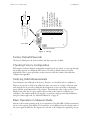


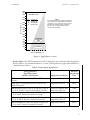
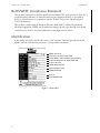
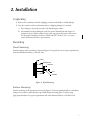
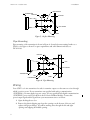
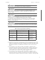

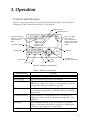
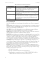
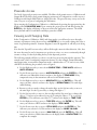

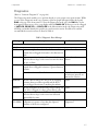
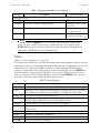


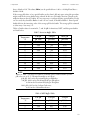
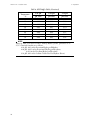
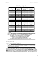
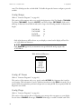


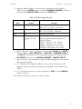


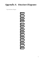

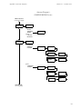
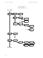
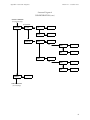
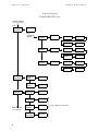
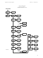
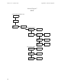
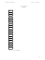


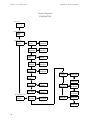
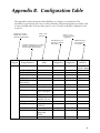
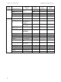
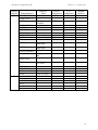
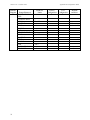
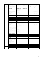
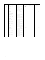

![MI 611-214] PH12 Series pH Sensors and Accessories](http://vs1.manualzilla.com/store/data/006880291_1-d8cfb499f5d4ccda8442b39d1f113a5e-150x150.png)
![[MI 020-495] Intelligent Field Device Configurator (IFDC](http://vs1.manualzilla.com/store/data/005940861_1-a7935b4637e46504f46a4e10b51d80ec-150x150.png)
![[MI 611-225] Model 875PH, Style C Intelligent](http://vs1.manualzilla.com/store/data/005757319_1-1ee84ed274e85c607e950fedd7484b8e-150x150.png)