1
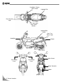
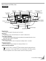
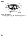
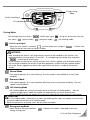
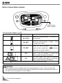
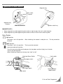
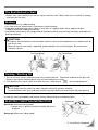
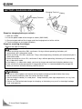
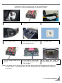
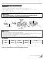
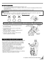
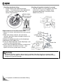
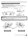
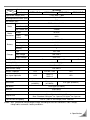
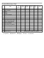
Periodical Maintenance Chart
Item
First
month
Every
month
Every 3
months
Every 6
months
1
Motor
I
2
Motor Controller
I
5
Battery
I
I
6
Charger
I
I
7
DC to DC Converter
I
I
8
Tire
I
I
9
Tire Pressure
I
I
10 Brake Clearance
I
I
11
I
I
Light / Electrical System / Meter
A
12 Electric Throttle Operation
I
13 Steering Handlebar
14 Bolt / Screw / Nut Tightness
I
I
I
15 Main Stand / Spring
I
16 Suspension / Oil Leakage
I
17 Frame Parts Lubrication
L
18 Transmission Belt
19
Transmission Oil
I-Inspection
A-Adjustment
Every 1
year
I
R
R-Replace
Replace every 4 months or 2000km
C-Clean
L-Lubrication
Note
Maintenance Record
1st month
Kilometer
Date
2nd month
km
/
/
3rd month
km
/
/
4th month
km
/
/
5th month
km
/
/
6th month
km
/
/
km
/
/
Distributor
7th month
Kilometer
Date
8th month
km
/
/
9th month
km
/
/
10th month
km
/
/
11th month
km
/
/
12th month
km
/
/
km
/
/
Distributor
13th month
Kilometer
Date
14th month
km
/
/
15th month
km
/
/
16th month
km
/
/
17th month
km
/
/
18th month
km
/
/
km
/
/
Distributor
19th month
Kilometer
Date
Distributor
20th month
km
/
/
21st month
km
/
/
22nd month
km
/
/
23rd month
km
/
/
24th month
km
/
/
km
/
/
25th month
Kilometer
Date
26th month
km
/
/
27th month
km
/
/
28th month
km
/
/
29th month
km
/
/
30th month
km
/
/
km
/
/
Distributor
31st month
Kilometer
Date
32nd month
km
/
/
33rd month
km
/
/
34th month
km
/
/
35th month
km
/
/
36th month
km
/
/
km
/
/
Distributor
37th month
Kilometer
Date
38th month
km
/
/
39th month
km
/
/
40th month
km
/
/
41st month
km
/
/
42nd month
km
/
/
km
/
/
Distributor
43rd month
Kilometer
Date
44th month
km
/
/
45th month
km
/
/
46th month
km
/
/
47th month
km
/
/
48th month
km
/
/
Distributor
Note:1. Bring this maintenance record while maintaining and repairing your scooter.
2. Expendable replacement items and abnormal usage are not applicable to the warranty.
Please read the warranty procedure.
3. Please carry out maintenance in accordance with the Maintenance Record.
4. Whlie running out of the Maintenance Record, please copy and add it to the original.
km
/
/
This manual describes the correct usage of this vehicle including safe riding, simple inspection methods
and so on.
For a more comfortable and safer riding, please read this manual carefully.
For your benefit, please ask your SYM dealer the operating manual and read the following:
Correct usage of the vehicle.
Pre-delivery inspection and maintenance.
Usage of warranty, warrant contents, and warranty period.
In case the vehicle’s specifications and construction are modified and different from the photos and
diagrams on the owner’s manual / catalogues, the specifications and construction of the actual vehicle shall
prevail.
◎Safety Suggestion◎
◎
We concern the safety of both you and your scooter, thus, in this manual we provide safety suggestions
of the scooter usage. Please read carefully and follow the safety suggestions. These safety
suggestions indicate some potential dangers which may cause injury; each safety suggestion has specific
warning mark, symbol, or notation illustrated below:
Warning
Disobeying of this mark may lead to serious injury or even death.
Caution
Disobeying of this mark may lead to hurt or even serious injury.
Attention
Disobeying of this mark may lead to hurt.
◎Every safety suggestion has notation telling you what danger may happen and how to avoid or reduce
the risk.
◎In addition to the three safety suggestions mentioned before, there is also another important mark in
this manual—Note ; disobeying this mark may result malfunction of your scooter.
1. Contents ......................................................................................................................... 1
2. Control Location ............................................................................................................ 2
3. Warranty Method ........................................................................................................... 3
4. Correct Riding Method .................................................................................................. 4
Use Genuine Spare Parts .................................................................................................... 4
Safe Riding ....................................................................................................................... 4
Riding Method ................................................................................................................... 5
5. Use of Each Component ............................................................................................... 7
Gauges ............................................................................................................................. 7
Main Switch / Handlebar Lock Operation ............................................................................. 11
Button Operation .............................................................................................................. 12
Seat Lock ........................................................................................................................ 12
Note on Starting to Ride .................................................................................................... 13
Brake .............................................................................................................................. 13
Parking / Shutting Off ........................................................................................................ 13
Electric Throttle Instruction ................................................................................................ 14
Battery Charging Instruction .............................................................................................. 14
Battery Charging Procedure .............................................................................................. 15
Battery Usage Instruction .................................................................................................. 16
Battery Charger Usage Method .......................................................................................... 17
6. Inspection and Maintenance before Riding ............................................................... 19
Tire Inspection ................................................................................................................. 19
Steering Handlebar Inspection ........................................................................................... 19
Brake Lever Free Play Inspection & Adjustment ................................................................... 20
Transmission Oil Replacement .......................................................................................... 20
Maintenance ................................................................................................................... 21
Motor Usage Notes .......................................................................................................... 21
Motor Controller Usage Notes ............................................................................................ 21
7. Troubleshooting .......................................................................................................... 22
8. Specification ................................................................................................................ 23
9. SYM Electric Scooter Q & A ........................................................................................ 24
1. Contents
1
Headlight / Starter
/Horn Switch
Luggage Box
Front Position
Light
Turn signal light
Horn switch
Winker /
Luggage Box
Lock
Rear Turn
Signal Light
Headlight
Frame
Number
Taillight
Battery
Side Stand
Main Stand
Front Brake
Lever
Rear Brake
Lever
Main Switch
Motor Controller
Motor
2
2. Control Location
This manual describes the correct usage of this vehicle including safe riding, simple inspection methods
and so on.
For a more comfortable and safer riding, please read this manual carefully.
For your benefit, please ask your SYM dealer the operating manual and read the following:
Correct usage of the vehicle.
Pre-delivery inspection and maintenance.
In case the vehicle’s specifications and construction are modified and different from the photos and
diagrams on the owner’s manual / catalogues, the specifications and construction of the actual vehicle
shall prevail.
SAFE RIDING
It is very important to be relaxed and wear properly while riding, observe traffic regulations, do not rush,
always ride carefully and relaxed.
Usually, most people would ride their newly bought vehicle very carefully, but after they become familiar
with their vehicle, they tend to become reckless which may result in an accident.
To remind you:
Please wear a helmet, and properly tighten the helmet belt when riding.
Clothes with open or loose cuffs may be blown by wind and cause the cuffs caught on the steering
handlebar and thus affects riding safety. So put on clothes with tight sleeves.
Hold the steering handlebar by both hands when riding. Never ride with only one hand.
Observe the speed limit.
Wear suitable low-heel shoes.
Perform periodical maintenance and inspection in accordance with the schedule.
CAUTION:
Modified vehicle will affect its structure or performance, and cause poor engine operation or exhaust
noise, which will result in shorter vehicle service life.
Besides, modification is illegal and does not conform to the original design and specifications.
A modified vehicle will not be covered by warranty. Therefore, do not modify your vehicle at will.
Tire and rim modifications will make it unsafe to ride and may cause severe injury or death.
3. Before Riding
3
Keep your body such as shoulders, arms, palms, and waist relaxed and ride with the most comfortable
posture in order to react quickly when necessary.
Riding posture will greatly affect riding safety. Always keep your body’s gravity in the center of the
seat. If your body’s gravity is on the rear part of seat, the front wheel load will be reduced, and this
will cause the steering handlebar shaking. It is dangerous to ride a vehicle with an unstable
handlebar.
It will be much easier to make a turn when the rider inclines his body inward. On the contrary, the
rider will feel unstable if his body and the vehicle do not incline when making a turn.
The vehicle is hard to control on a bumpy, unleveled, unpaved road. Try to know the road
conditions in advance, slow down and use your shoulder’s force to control the handlebar.
Suggestion: Do not load unnecessary objects on the front floor panel; avoid affecting the riding
safety and the operation of steering handlebar.
CAUTION:
The rider’s feeling on the handlebar is slightly different with or without a load.
Overload may cause the handlebar to swing and affect the riding safety.
Therefore, do not overload your vehicle.
Overload will cause the vehicle become unstable and hard to control, it may cause serious damage to
the tires and rims; it may also change the center of gravity, which could result in an accident that could
cause injury or death. Do not exceed the maximum authorized load.
USE GENUINE SPARE PARTS
To maintain the vehicle’s best performance, each part’s quality, material, and machined precision must
conform to the design requirements.
“SYM Genuine Spare Parts” are made from the same high quality materials used for the original vehicle.
No parts would be sold to the market until they could meet the designed specifications through
sophisticated engineering and stringent quality control.
Therefore, it is necessary to purchase “SYM Genuine Spare Parts” from “SYM Authorized Dealers or
Franchised Dealers” when replacing spare parts.
If you buy the cheap or fake substitute parts from the market, neither quality nor durability will be
guaranteed.
Also, it may result in unexpected troubles and reduce the vehicle’s performance.
Always use SYM Genuine Spare Parts to ensure its long service life.
4
4. Riding
Basic Controls of SYM e-Virid
GAUGES
Abnormal
Indicator
Odometer
Energy-saving
Mode
Turn Signal
Indicator
Automatic on & off
headlight /
UV Sensing Window
High Beam
Indicator
Charging Indictor
Battery Volume
Status Indicator
Vehicle Lock Signal
Driving Mode
SET Button
MODE Button
Speedometer
Speedometer
This shows the speed in kilometers per hour (km/h).
Odometer
This odometer shows the total kilometers this motor has been driven.
Turn Signal Indicator
The left or right Indicator will be flashing according to the operated directions of turn
signal light switch when it is turned on.
High Beam Indicator:
This indicator comes on when the high beam headlight switch is turned on.
Charging Indicator
When the battery is being charged, the charging indicator is on.
Battery Quantity Indicator
When the main switch is turned to
〝
with the battery quantity gauge pointing to
〞, the battery is fully charged;when consuming the power, the battery quantity
indicator will go down, each section indicates around 10% battery quantity.
5. Use of Each Component
5
SET Button
Mode Button
Adjustment of SET / MODE Button
When key switch is turned to “
”, Press “MODE” button to change between “TOTAL” and ”TRIP”
modes. Under TRIP mode, press “SET” button continuously to reset the TRIP kilometer readings.
6
5. Use of Each Component
Energy-saving
Mode
Vehicle Lock Signal
Driving Mode
Driving Mode
〞,vehicle lock signal〝
Pull the brake lever then press〝
can switch:〝
〝
〞(normal mode),〝
〞(economic mode),〝
〞will go off, at the mean time you
〞(hill-climbing mode).
〞Vehicle Lock Signal
〞, pull the brake lever and press〝
Signal will go off, then you can ride the scooter.
When the main switch is turned to〝
〞, Vehicle Lock
CAUTION:
After unlocking the vehicle, it will automatically transfer to lock condition if the vehicle is not
operated (without turning throttle) in 5 minutes. It is needed to pull the brake lever and press
〝
〞, to activate to vehicle again.
In the situation of unlocking the vehicle while the main stand is applied, turn the throttle and the
rear wheel go unloaded, the vehicle will go idling protection, and there will be no power output.
If the side stand is applied, the vehicle lock signal will be on, and it is unable to activate the
vehicle.
〝
〞Normal Mode
The scooter operates at its max efficiency. The max speed is around 50km/h on level road
condition.
〝
〞Economic Mode
The scooter operates at its most economic efficiency to carry out the best durability. The max
speed is around 30km/h.
〝
〞Hill-climbing Mode
Hill-climbing Mode will increase the motor torsion to enhance hill-climbing ability. After 30
seconds of applying this mode, the scooter will automatically transfer to normal mode.
While used on flat road, the scooter will increase its motor torsion and increase its acceleration.
CAUTION:
If the hill-climbing mode is continuously used on flat road or gentle slope, the scooter will not transfer
to normal mode and maintain at hill-climbing mode.
While changing lanes or making a turn, do not switch the modes.
〝
〞Energy-saving Mode
When riding on flat road condition, 〝
〞indicates the scooter is operated at the most
energy-saving state.
5. Use of Each Component
7
Battery Volume Status Indicator
Battery Volume
Status Indicator
Turn the main switch to〝
〞
Battery Volume Status
Remaining power
Condition
90~100%
Shows the remaining power is full and at its
best durability.
40~50%
Show the remaining power is 40-50%. Avoid
long distance riding.
Shows the remaining power is 1/3, and the
20~30%
system will be compelled to 〝
〞economic
mode; the max speed is 30km/h.
+
+
+
10%
The two signals flash shows the remaining
power is low, the durability is around 4km;
please charge the battery immediately.
5%
The three signals flash show the remaining
power is extra low, the durability is around 2km;
please charge the battery immediately.
Note: It is suggested that to charge the battery to its full capacity after each riding.
CAUTION:
When the battery volume indicator shows the remaining power less than 1/3, the system will be
transferred to economic mode to keep the best durability and cannot be switched to other modes; at
the mean time the top speed is less than 30km/h.
8
5. Use of Each Component
Operation of Main Switch
Magnetic key
Main switch
keyhole
Magnetic key
keyhole
IGNITION SWITCH
Ignition switch key
MAGNETIC KEY:
:
•
•
Align magnetic key and magnetic keyhole and turn right to open the main switch keyhole.
Align magnetic key and magnetic keyhole and turn left to shut the main switch keyhole.
Main Switch
“ON” position
The motor is on in this position. After unlocking, the scooter is ready for use.
removed.
The key cannot be
“OFF” position
The motor is off in this position. The key can be removed.
“steering handle lock” position
Turn the steering handle to left and press the key down and then lightly turn it to lock.
The key can be removed.
When unlocking. Simply turn the key from “lock” to “off.”
High/Low Beam Switch
Light switch
Seat open switch
Turn signal switch
Horn switch
Starting Button/
Mode Switch
5. Use of Each Component
9
Use of Buttons
Light Switches
When the switch is turned to this position, all lights will go off.
When the switch is turned to this position, headlight, position light, rear light, and panel light will
automatically be on or off according to the environment.
When the switch is turned to this position, position light, rear light, and panel light will come on.
When the switch is turned to this position, headlight, position light, rear light, and panel light will
come on.
Starting Button
To activate the motor, press this button.
Turn the main switch to “ ”position, pull brake lever after gauge checking system, then press
this button to activate the motor.
Turn Light Switch
Turn the main switch to “ ”position, turn the turn light switch, and the turn light will flash.
When using turn light, the turn light signal will flash in accordance with the turn you make.
Horn Switch
Turn the main switch to “
”position, press this button, and the horn will sound.
Seat Lock
• Unlocking method: 1. Insert the key to the keyhole on left side panel, then turn the key right
to open the seat.
” to open the seat.
2. Press “
Lock:Press the saddle down and it will be locked automatically.
10
5. Use of Each Component
The Best Method to Start
Before start, you should turn on the turn signal, watch the rear side to make sure no vehicle is coming,
and then you can start.
Braking
Avoid unnecessary sudden braking.
Use front and rear wheel brakes simultaneously when braking.
Slow down and brake early when riding in rainy days on slippery roads. Never apply the brakes
suddenly to prevent skidding and falling.
Avoid brake continuously for a long period of time because that may overheat the brakes and reduce its
braking efficiency.
CAUTION:
Using only the front brake or the rear brake increases the risk of falling because the scooter tends to
pull to one side.
When the front or rear brake is operated, speed controller will cut off the power. Be careful when
riding the vehicle.
For Rear Wheel
For Front Wheel
Parking / Shutting Off
1. Turn on the turn signal in advance to warn the vehicles behind. Decelerate and ride to the right side.
Reverse the electric throttle and pull front and rear brake levers slowly.
2. Push back the turn signal switch and rotate the main switch key to 〝
〞 to cut motor power off.
CAUTION:
Do not rotate the main switch key when riding the vehicle to avoid an accident.
To avoid children from injury and theft, lock the steering handle and removing the key after parking.
3. Park the vehicle on level ground with the main stand.
4. Lock the steering handlebar and remove the key after parking to avoid being stolen.
ELECTRIC THROTTLE INSTRUCTION
Accelerate:
:Increase riding speed.
If brake lever is pulled, the electric throttle will be cut
off power.
Decelerate
Accelerate
Decelerate:
:Decrease riding speed.
5. Use of Each Component
11
BATTERY CHARGING INSTRUCTION
Charging Terminal
Battery
Charging Terminal
Steps for charging battery on vehicle:
1. Open the saddle
2. Insert the power cable of the charger to socket (100V-240V)
3. Connect output cable of the charger and the charging terminal of the vehicle
4. Turn the charger on to charge the battery
Steps for removing the charger:
Reverse the steps of charging.
CAUTION:
Power remaining more than 50%, continuous 14 days without operating, the battery will
automatically be in hibernation mode.
Power remaining 15%-50%, continuous 7 days without operating, the battery will automatically be in
hibernation mode.
Power remaining less than 15%, continuous 2 days without operating, the battery will automatically
be in hibernation mode.
If the battery is in hibernation mode, you have to charge and reactivate the battery before using.
If the vehicle will not be operated for a long period of time, it is recommended to fully charge the
battery to maintain the best efficiency and life service.
WARNING:
Please turn off the power and remove the key before charging to avoid children from injury.
Do not remove the battery from the vehicle and then charge.
Please charge the battery at a cool place. Keep the battery from high temperature, sun ray, heat,
fire, and water.
Please use SYM authorized charger for charging, or the battery may result in electrolyte leakage,
heat, and explosion.
12
5. Use of Each Component
STEPS FOR CHARGING THE BATTERY
1. Turn off main switch
2. Keep charger switch on “OFF”
position
3. Open luggage box
4. Open charging cover
5. Connect charging terminal
(Note: Be aware the direction of
the charging terminal)
6.
7.Turn the charger switch to “ON”
position.
8.The charger will show orange
light (charging) or green light
(fully charged).
9.The gauge will show the
battery power while charging.
Connect the charger
AC100V-240V
to
Note: If the charger shows no light or flashes red light, please check the charging terminal and turn on
the switch again. If the charger light still shows no light or flashes red light, please contact your
SYM dealer.
5. Use of Each Component
13
INSTRUCTION OF BATTERY USAGE
Specification:
:
Type
Voltage
(V)
Capacity
(Ah)
Li(Ni Co Mn) O2
48
20
Length
(mm)
Size
Width
(mm)
Height
(mm)
393
246
417
Weight
(kg)
10.2
Usage Method:
:
Turn off main switch before charging.
Fully charge the battery before the first ride.
Charge the battery after each ride.
Charge at least once every 3 months, if the vehicle does not operate for a long period of time.
Charge the battery on the vehicle. Do not remove the battery.
CAUTION:
Please use the SYM authorized battery. For the safety of electrical parts, do not use unauthorized
battery.
Keep the battery clean.
Keep children away while charging.
WARNING:
When deformation, leakage or corrosion occurs to the battery case, stop using the battery immediately
and contact your SYM dealer for help.
Do not disassemble, restructure or destroy the battery.
Do not dispose the battery or throw it into fire; recycle it at recycle plants or local dealers.
Factors that affect the life span of the battery:
:
(1) Over Discharge:
a. Not in use for long period of time without charging.
b. The battery is not recharged when it is empty.
(2) High-Rate Discharge:
a. Frequent riding at max. speed.
b. Frequent riding on the slope.
c. Frequent riding on the rugged road.
d. Over-loaded.
(3) Others:
a. Vehicle parts worn out.
b. Charger malfunction.
14
5. Use of Each Component
BATTERY CHARGER USAGE NOTES
Usage Method:
:
1. Insert the charger output plug into the charging terminal on the battery.
2. Connect charger cable plug “A” to AC power, and connect charger cable “B” to the charger.
3. Turn on charger power switch.
4. Check LED status indicator.
5. When the battery is fully charged, the green light is on.
CAUTION:
Make sure the power switch on “OFF” position while connecting and removing charger cable.
Use the battery charger indoors; avoid hot, humid or dusty environment.
B
A
Power Input
Socket
Status Indicator
Charger
Charger Cable
Power Switch
WARNING:
Prevent the charger from striking, pressing, and falling.
Use the charger indoors. Do not place the charger in the luggage box to avoid shocking and moisture.
Do not place the charger in the luggage box while charging to avoid heat.
Keep children away while charging.
Please park the vehicle along the wall or in the corner while charging to avoid tripping people.
LED Indicator
LED
Orange
Green
Red Flash
No Light
Mode
Charging
Fully Charged
Abnormal
Cable disconnect or power
switch off
LED Red Flash:
Low input voltage, fan malfunction, over-heat protection, battery disconnection, battery low voltage,
charger over voltage protection, overtime charging, battery malfunction
5. Use of Each Component
15
Troubleshooting
Detection Item
Unable to charge
Long time charging without
green light on
Possible causes
Countermeasures
Charger power switch off
Turn power switch to “ON”
Not using SYM authorized
battery
Using SYM authorized battery
Low input voltage
Power input 100V~240V
Battery
deterioration
malfunction
or
Replace battery
If problems cannot be eliminated, please contact your SYM dealer.
CHARGER USAGE INSTRUCTION
Specification:
Model
Input Voltage
Output Voltage
Charging Time
Battery Type
48V 10A
100~240 VAC
48 VDC
2~3 hour
LiFe Battery (20Ah)
Charger Usage Instruction:
Keep power switch on “OFF” position before charging
Connect charger output cable and battery first, then connect power cable and 100V-240V socket.
Orange light shows the battery is being charged; green light means charging finished, the battery is fully
charged, please stop charging.
Please use SYM authorized charger.
CAUTION:
While connecting or removing cables, please make sure the power switch on “OFF” position.
Please charge the battery indoors, avoid sun ray, moisture, and dust.
Prevent rain, liquid, foreign metal material from falling into the charger to avoid short circuit or burnout.
After charging, please remove the cables from the socket to avoid power consuming.
Do not charge battery of other form and brand with the charger to ensure the life span and safety of the
charger and battery.
CAUTION:
The AC pug is 3P mode; do not modify it to 2P mode to prevent electric shock.
In normal temperature, the battery can be fully charged in 2-3 hours; however, if the ambient
temperature or battery temperature is too high (over 55℃) or too low (under 0℃), to prevent
deterioration, the charger will prolong the charging time to 4-5 hours.
When the charger indicator light does not come on, red light flashes, or the battery cannot be fully
charger, please shut off the charger for 5 seconds, then turn on the charger again to correct the
situation. If this situation still cannot be solved, please contact your SYM dealer.
WARNING:
Use independent socket for the charger, do not share the socket with electric equipment to avoid danger
and fire.
When charging, the fan will make louder noise, which is a normal phenomenon.
Do not disassemble or strike the charger. Warranty will not be applicable if consumers disassemble
the charger or there is obvious damage on the charger.
16
6. Inspection and Maintenance before Riding
TIRE INSPECTION
Tires should be checked and inflated when the engine is off.
If a tire’s ground contacting curve is abnormal, check it with a tire pressure gauge and inflate it to the
specified pressure.
Tire pressure must be checked with a tire pressure gauge when the tire is cold.
CAUTION:
If the tire pressure is insufficient, it will affect the riding range of the vehicle and the life span of the
battery and motor. Tire pressure inspection is suggested every month.
PLEASE REFER TO SPECIFICATIONS FOR STANDARD TIRE PRESSURE
Foreign materials
(Nails or small stones)
Visual check tires for frontal and lateral side walls
for crack or damage.
Crack and
damage
Visual check tires for any nails or small stones
wedged in the tread.
Check the “tread wear indicator” condition to see if
tread groove depth is insufficient.
A tire with a wear bar showing is worn out and
should be replaced immediately.
Minimum tread
depth indicator
Tread wear
indicator
STEERING HANDLEBAR INSPECTION
Switch off the power and remove the key before inspecting.
Visual check the front shock absorbers for any damage.
Operate the steering handlebar up and down, and check
the front shock absorbers for noises due to bends.
Check the bolts and nuts of front shock absorbers
with wrenches for tightness.
Shake the steering handlebar up & down, left & right, and
front & rear to check if it is loosen or pulled to one side.
Check the steering handlebar if it is pulled too tight
by the brake cables.
Take your vehicle to SYM Authorized Dealer for a check or
adjustment if abnormal conditions are found.
6. Inspection and Maintenance before Riding
17
Checking front brake lining
• Check the brake from behind the brake
caliper. The brake pad must be replaced with
new lining when the brake pad wear limit
reaches the brake disk.
Checking oil quantity in brake oil reservoir
• Park the scooter on a level ground, and check
if fluid level is under the “LOWER” mark.
Recommended Brake Fluid: WELL RUN
BRAKE OIL (DOT 3).
Brake caliper
Brake pad wear
limit grooves
Brake disk
Replenishment of front wheel brake fluid
1.Loosen the screws and remove the master cylinder
cover.
2.Wipe clean foreign materials, dirt around the
reservoir, be careful not to let foreign materials fall
into the reservoir.
3.Remove the diaphragm plate and the diaphragm.
4.Add brake fluid to upper level.
5.Install the diaphragm plate and the diaphragm, and
install the master cylinder cover.
6.Please note the diaphragm direction, and do not let
foreign materials fall into the reservoir. And
tighten the master cylinder cover securely.
Screw
Master
cylinder cover
Diaphragm
Upper
Brake fluid
CAUTION:
• To prevent chemical reaction, please do not use brake fluids other than those recommended.
• Do not fill above the upper limit when adding brake fluid and avoid dropping on painting or plastic
components to prevent damage.
6. Inspection and Maintenance before Riding
18
INSPECTION AND ADJUSTMENT OF BRAKE FREE PLAY
INSPECTION:(Brake lever free play must be checked with the engine off.)
Brake lever free play for front and rear wheels.
When checking the hand-braking lever for front and rear wheels, its free play (the stroke of
hand-braking lever from no braking to initial braking) should be 10~20mm. It is abnormal if the feel
is spongy when holding the hand-braking lever forcefully.
Adjustment:(Drum type)
The indentation of brake adjustment nut must be aligned with the pin.
(see below figure)
Adjustment nut
10~20 mm
Pin
CAUTION:
:
When free play is between 10~20 mm, check brake indicators of front and rear wheels. If the arrow
on the brake arm aligned with the “△” marked on the brake disk, that means the brake lining has been
excessively worn, and must be replaced immediately.
Turn the adjustment nut on brake arm of front and rear wheels to adjust the free play of hand-brake lever.
Hold the hand-brake levers after adjusting with both hands until there is effective brake feeling.
Measure the free play with a ruler.
To decrease
free play
To increase
free play
To decrease
free play
Front wheel drum type
To increase
free play
Adjustment nut
Rear wheel drum type
6. Inspection and Maintenance before Riding
19
TRANSMISSION OIL REPLACEMENT
• Park the vehicle on level ground, remove infusion and
drain bolts, drain out the transmission oil.
• Install the drain bolt and tighten it. Fill new 100 c.c.
transmission oil; install and tighten the infusion bolt.
Make sure bolts are tightened and check for leakage.
• Recommend Oil: Genuine SYM HYPOID GEAR
OIL(SAE 10W-40)
Infusion Bolt
• Replace transmission oil on the first 300km, then
replace it every 4 months or 2000km.
Drain Bolt
MAINTENANCE
1. Routine Maintenance
Turn off the main switch and remove the key before performing inspection and maintenance.
Clean the dust and mud around the motor and every part of the vehicle periodically.
Check if the brake, light and tire operate normally.
Check if the screws or bolts are loose; adjust them properly.
CAUTION:
Do not spray the vehicle body and motor with high pressure water to avoid affecting the performance and
life span of the vehicle.
Use neutral cleanser and soft cloth to wash and wipe the vehicle.
2. Periodical Maintenance
Periodical inspection and maintenance at SYM dealer every month is suggested to lengthen the life
span and riding safety of the vehicle.
20
6. Inspection and Maintenance before Riding
INSTRUCTION OF MOTOR USAGE
Specification:
:
Model
ED1LU
Type
DC
Brushless
Hub Motor
Voltage
Max Power
48 VDC
2200 W
Caution
Please avoid overload, steep slope, and long period of power-consuming condition; it may damage
battery, motor controller, and motor.
Do not spray high pressure water toward motor assembly.
Do not ride across the flooded road over 10cm high.
Do not disassemble the motor assembly.
CONTROLLER USAGE INSTRUCTION
Specification:
Model
ED1LU
Voltage
48 VDC
Max Power
60 A
Usage Method:
:
Avoid rotating the electric throttle rapidly; high current operation may lead to high temperature of the
motor controller.
Function:
:
Controlling the current intensity, braking cutoff protection, malfunction cutoff protection, rotation-clogging
protection and over-heating protection.
CAUTION:
Avoid long time solarization, rain to secure the controller.
Do not disassemble the controller.
6. Inspection and Maintenance before Riding
21
Troubleshooting
Detection Item
Possible Causes
Countermeasures
Power cable of battery is
not connected.
Reconnect the power cable and then switch
on.
Reconnect the inner cable and then switch
on.
If the coupler is loose, reconnect it. If the
coupler is ok, there might be open circuit in
the wire harness. Please contact your SYM
dealer.
Replace the main switch
1 Recharge the battery. Check if the battery
voltage is 52V.
2. Replace the battery when the voltage is
under 30V after recharging.
1. Replace DC/DC Converter.
2. Replace fuses (5A / 15A).
3.Contact your SYM dealer.
Replace the main switch
Reinstall
Battery inner cable loose
1.
Meter doesn’t work
and indicator doesn’t
illuminate.
Main
loose
switch
coupler
Main switch malfunction
Low battery voltage
2.
3.
4.
5.
Malfunction of light
system
DC / DC
Converter malfunction
Rear wheel does not
rotate when the
electric throttle is
rotated.
Faulty main switch
Motor wire loose
Ineffective
motor
position feedback signal
Motor malfunction
Motor
controller
overheated
Motor
controller
malfunction
Unable to charge
the battery
(orange light
means charging)
Riding mileage is too
short.
Charger coupler is not
plugged properly.
Charger malfunction
Front / rear brake too
tight
Long
time
without
charging
Low temperature
Low tire pressure
Aged battery
22
7. Troubleshooting
Contact your SYM dealer
Re-plug coupler.
Replace the charger.
Adjust front / rear brake.
Recharge after riding or when the vehicle is
not in use for a long time.
Battery quantity will decrease when the
temperature is low.
Check the tire pressure periodically (every
month) and inflate the tire to the
recommended pressure.
Replace the battery
e-Virid
Model
Item
Specification
ED1LU1-6
ED1LU2-6
ED1LU3-6
length/width/ Height (mm)
81Kg / 1,215
Net Weight/Wheel base (mm)
745
Seat Height (mm)
DC Brushless Hub Motor
Type
Motor
Motor
Controller
Rated Power (W)
1800 W
Max. Power (W)
2200W
voltage
48 VDC
Output
Current
Max
60 A
Type
Battery
Li(Ni Co Mn) O2
voltage
48 V
Capacity (Ah)
20 Ah
Quantity
1
Type
Charger
ED1LU1-F
1,725 / 625 / 1,060
48V 10A
Input voltage
100~240 V
Output voltage
53.3 VDC
45
Max. Speed (km/hr)
25
45
13°(23%)以上
Climbing Ability
Front light bulb(high, low)
12V 35W / 35W×1
Front Position Lamp
12V 5W×1
Taillight / Stoplight
LED
12V 5W / 21W
LED
Turn signal light bulb
LED
16W×2
10W×2
LED
Fuse
Front brake
Rear brake
Front tire
Rear tire
Tire pressure
Transmission oil capacity
5A×1
Disk type
(ø160mm)
Drum type
(ø110mm)
Disk type (ø160mm)
Drum type (ø110mm)
3.00-10 42J
3.00-10 42J
Front: Standard 1.8kg/cm2,
Rear: Standard 2.0 kg/cm2 for 1 person,2.3 kg/cm2 for 2 person
110 ㏄. (100 ㏄. for change) SAE 10W-40
※Note:Max. speed and riding mileage change according to the traffic conditions, rider’s weight,
riding habits and motor / battery conditions.
8. Specification
23
1. How is the SYM electric scooter capability of riding across flooded road? Is the motor waterproof?
A: The motor is capable of being drenched, but the waterproof capability is not good when being soaked.
Do not ride across the flooded road when the water level is higher than the wheel rim (approximately
10cm high).
2. Can SYM electric scooter be ridden in the rainy day? How is the waterproof capability?
A:Yes, but do not ride across the flooded road when the water level is higher than the wheel rim
(approximately 10cm high), or the motor could possibly suffer from being soaked (the waterproof
capability of motor depends on the gasket adhesive; the waterproof capability can not be
guaranteed after disassembly). Spraying on the motor and wire harness with high-pressure water
is extremely prohibited, which will result in short circuit.
3. What will happen to the battery and motor if the vehicle is soaked in the water with the water level
higher than the footrest when the main switch is key-off? What will happen if the water level is higher
than the footrest when the main switch is key-on?
A:The motor, motor controller and DC-to-DC converter could be possibly damaged because of being
soaked when the water level is higher than the footrest. The damage would be worse if the main
switch is key-on. Only the battery could possibly survive damage, but might malfunction because
of short circuit caused by other parts’ damage.
4. Can SYM electric scooter carry passenger or cargo?
A:This vehicle can carry a passenger, but it is not recommended to carry cargo.
150KG. Load increase will affect vehicle durability.
Max passenger load:
5. Battery charger input voltage?
A:Use the electrical socket (100V~240V)
6. How long is the charging period?
A:1. The battery needs to be charged 2-3 hours (20Ah),The battery has no memory effect and could
be recharged overnight, In the situation that the ambient temperature or the battery temperature
too high (more than 55℃) or too low (less than 0℃), to avoid battery deterioration, the battery
will automatically prolong the charging time to 4-5 hours.
2. It is recommended to recharge after each ride to prolong battery service life.
3. In long time not in use, it is recommended to fully charge the battery every 3 months to prolong
battery service life.
7. Is there any side effect when the charger is still plugged to the electrical socket after the battery is
removed?
A: The charger will not be heated when it is plugged to the electrical socket, but would consume standby
power.
8. How much will the riding range decrease when the headlight is turned on?
A: Approximately 10~20% less.
24
9. SYM Electric Scooter Q & A
SYMEN201202