1
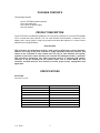
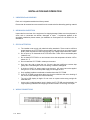
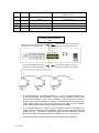
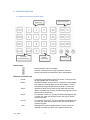
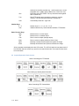
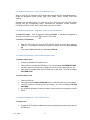
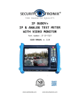
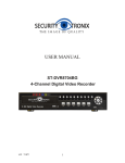
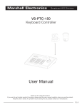
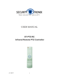
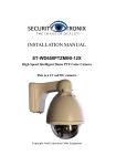
USER MANUAL ST-PTZ-KB PTZ Keyboard Controller v1.0 8/5/11 1 TABLE OF CONTENTS PACKAGE CONTENTS....................................................................................................3 PRODUCT DESCRIPTION ...............................................................................................3 SPECIFICATIONS ...........................................................................................................3 INSTALLATION AND OPERATION ..................................................................................4 1. UNPACKING and HANDLING ....................................................................................................................... 4 2. MECHANICAL INSPECTION.......................................................................................................................... 4 3. SPECIAL ATTENTION .................................................................................................................................... 4 4. WIRING CONNECTIONS ................................................................................................................................ 4 5. KEYBOARD OPERATION .............................................................................................................................. 6 5.1 Keyboard Controller Function Keys ................................................................................................................... 6 5.2 Joystick/Operation Knob Control ......................................................................................................................... 7 5.3 Keyboard Operations – Single and Combined Keys................................................................................. 8 5.4 Keyboard Operations – PTZ Mode and Choosing PTZ Address........................................................ 8 5.5 Keyboard Operations – Set and Recall Pattern Scan .............................................................................. 8 5.6 Keyboard Operations – Set and Recall Tour ................................................................................................ 8 5.7 Keyboard Operations – Set and Recall Preset Points ............................................................................. 9 5.8 Keyboard Operations – Turn On/Off Auxiliary ............................................................................................10 6. SETTING KEYBOARD PARAMETERS............................................................................................... 10 6.1 Setting Controller Protocol and Baud Rate ..................................................................................................10 6.2 Keyboard Controller System Parameter Setup..........................................................................................11 6.3 Keyboard Controller Parameter Setup Framework..................................................................................12 7. TROUBLESHOOTING TIPS ........................................................................................................................ 12 v1.0 8/5/11 2 PACKAGE CONTENTS This package contains: One ST-PTZ-KB keyboard controller One 5-pin Isobar plug One 12VDC 2A power supply One user manual PRODUCT DESCRIPTION The ST-PTZ-KB is a professional grade pan, tilt, zoom (PTZ) controller for up to 255 PTZ-enabled CCTV cameras and other devices. The unit uses RS-485 communications, includes an LCD display and a 3-axis joystick. Single key protocol and baud rate retrieval of a current control address is an innovative feature. Important Note PTZ controllers are designed to perform a wide variety of PTZ camera control functions. However, the utility of any PTZ controller is highly dependant upon the particular PTZ camera to be controlled as each camera has not only its own functions but specific methods of how those native functions are accessed and managed. Further, a particular PTZ controller’s terminology may differ from that used by a particular PTZ camera. Therefore, it will be necessary for the installer and/or user to consult BOTH the PTZ controller and PTZ camera’s user manuals to ensure proper set-up, configuration and application. SPECIFICATIONS ST-PTZ-KB Specifications (Typical) v1.0 1. Communications Protocol RS-485 Half-Duplex 2. Communications Distance Up to 3900 feet 3. Baud Rate 1200, 2400, 4800, 9600, and 19200 Bits/S 4. Interface 5 pin Pressure Line Terminal 5. Operating Temperature 14°F - 131°F 6. Relative Humidity <90% 7. Power Supply 12VDC 2A 8. Dimensions 12”x5.8”x3.2” 9. Weight 1.5 lb. 8/5/11 3 INSTALLATION AND OPERATION 1. UNPACKING and HANDLING Each unit is shipped assembled and factory tested. Ensure that all accessories are removed from the container before discarding packing material 2. MECHANICAL INSPECTION Inspect the front and rear of the equipment for shipping damage. Make sure the equipment is clean, and no connectors are broken, damaged, or loose. If equipment appears to be damaged or defective please contact your distributor or Securitytronix at 1-610-429-1511 for assistance. 3. SPECIAL ATTENTION a. The installer must comply with electrical safety standards. There must be sufficient space between the ST-PTZ-KB’s communication and power lines and camera’s and DVR’s power supplies and video lines and any high voltage equipment and/or cables. b. Do not open up or dismantle the ST-PTZ-KB’s case. There are no serviceable parts inside the unit. c. Do not install ST-PTZ-KB in an environment where the temperature is below 14ºF or above 131° F. d. Do not install the ST-PTZ-KB in a damp environment. e. Only use a dry cloth to clean the unit. If there is dirt that is difficult to remove wipe gently with a mild detergent. Never use strong or abrasive detergents. f. A minimum 12VDC 2A power supply must be used. AC power cannot be applied. Using an AC or other incorrect power supply will damage the unit. g. Only qualified installers are allowed to install and test the ST-PTZ-KB. h. As the ST-PTZ-KB is a sensitive device any shock or collision to the unit or shaking of the unit will cause damage and void the warranty. i. The unit’s LCD display is fragile. Do not crush or expose under strong sunlight for extended time. j. As the unit’s joystick/operation knob is fragile, the ST-PTZ-KB must be packed in its original packing material when shipping to another location or returning it for repair. 4. WIRING CONNECTIONS v1.0 8/5/11 4 1 PTZ-‐CON Control output (Ta/Tb) 2 PTZ-‐AUX 3 4 5 6 Ground Slave keyboard controller input (Ra, Rb) Grounding Connect to PTZ camera’s RS485+ port (Ta), RS485-‐ port (Tb) Connect to slave key port: Ra to Ta on slave, Rb to Tb on slave. Communications cable ground T/R PTZ indicator Display output status: Flicker and Green PW Power indicator Always on, Red DC-‐12V DC power input DC power input Secondary Control Equipment Ta Tb Keyboard controller of the 4 legs of Rb access control equipment Tb Keyboard controller of the 3 legs of Ra access control equipment Ta PTZ camera’s RS485 connection. Keyboard controller leg Ta (leg 1). PTZ camera’s RS485 connection. Keyboard controller leg Tb (leg 2). a. A control cable (e.g. unshielded twisted pair – UTP) is connected between the ST-PTZ-KB’s RS485+ (Ta) and RS485- (Tb) connectors (pin positions 1 and 2) to the PTZ camera’s RS485 port. Be sure the polarities of the keyboard and camera’s RS485 connections are consistent. If multiple PTZ cameras are to be controlled use a control cable to daisy chain one PTZ camera to the other. Again, ensure the RS485 control cable polarities interconnecting the cameras are consistent. b. If a secondary device (e.g., DVR) is to be controlled using the ST-PTZ-KB use a control cable to connect the device’s RS485+ port (Ra) to the keyboard’s PTZ-AUX RS485+ port (Ta – pin position 3). Repeat the cable connection between the devices RS485- port (Rb) to the keyboard’s PTZ-AUX RS485- port (Tb – pin position 4). c. v1.0 8/5/11 Connect the 12VDC 2A power supply to the ST-PTZ-KB’s power connector. 5 5. KEYBOARD OPERATION 5.1 Keyboard Controller Function Keys Basic Function Keys Number Keys PTZ Camera Setup and Recall Keys Address Selection Keys Function Keys Function Keys Back to previous menu and escape. Press for 3 seconds to set up key parameters and enter. Display the protocol and baud rate of the current address. PTZ Setup and Recall Keys Preset Pattern Patrol Aux On Aux Off Shot v1.0 8/5/11 Preset the original position of the PTZ camera. This key should be used together with a number key. Start/Esc to pattern record. Press for 3 seconds to record pattern then press for 3 seconds again to end record pattern. This key should be used together with the control knob or function key. Start/Esc to patrol record. Press to enter patrol set and press again to exit patrol set. This key should be used together with the control knob or function key. Turn auxiliary function on. This key should be used together with a number key. Note: the auxiliary function will vary by camera vendor and model. Turn auxiliary function off. This key should be used together with a number key. Note: the auxiliary function will vary by camera vendor and model. Recall the PTZ camera’s preset position. This key should be used with a number key. Note: some special functions are 6 Run Tour Auto achieved via recalling a preset (e.g., recall camera menu, recall integrated menu, pattern patrol, pattern scan, linear scan, etc.) Recall the stored PATTERN. This key should be used together with a number key. RUN PTZ camera patrol according to settings in camera memory. This key should be used with a number key. Automatically starts left – right scan. Number Keys 0–9 Cam Number keys 0, 1, 2, 3, 4, 5, 6, 7, 8, 9 Address selection key. Select decoder address, PTZ address. Basic Function Keys Near Far Tele Wide Open Close Manual focus on a close object. Manual focus on a distant object. Zoom in lens on object (enlarge object). Zoom out lens on object (widen the field of view). Manually increase the lens aperture to lighten the image. Manually decrease the lens aperture to darken the image. All key operations are displayed on the LCD screen. The LCD will switch to low power mode if the controller does not receive any input for more than 30 seconds. The screen will also return to its initial state. 5.2 Joystick/Operation Knob Control When Controlling the PTZ Camera When Setting Up the Keyboard Controller When Controlling PTZ Camera Menu v1.0 8/5/11 7 5.3 Keyboard Operations – Single and Combined Keys When a single key is pressed the PTZ camera will respond with the corresponding action. Single key operations include: NEAR, FAR, TELE, WIDE, OPEN, CLOSE, AUTO and Joystick. Combined key operators involve 2 or more keys or a key and knob to have the PTZ camera respond with the corresponding action. Combined key operations include: PRESET, PATTERN, PATROL, SHOT, RUN, TOUR, CAM, AUX ON, AUX OFF. 5.4 Keyboard Operations – PTZ Mode and Choosing PTZ Address To enter PTZ mode – If the LCD screen displays PTZ-XXX working in PTZ mode. If not, press to return to PTZ mode. it indicates the keyboard is To choose a PTZ address Enter the PTZ mode and input the PTZ address number to control then press the CAM key. For example, for address 28 press 2 8 and the LCD will display PTZ-001 28 Then press CAM key and the LCD will display PTZ-028. 5.5 Keyboard Operations – Set and Recall Pattern Scan To setup a pattern scan Choose the address for the pattern scan. Then press for 3 seconds PATTERN key. The LCD will display PATTERN RECORD. Use the joystick and control knob to position the camera, zoom, adjust the lens, etc. After setup is complete press the PATTERN key to end setup. The LCD will display PATTERN STOP. To recall a pattern scan Press the RUN key. The LCD will display RN PATTERN NO:. Note: In PELCOD there is only one pattern. The PTZ camera will operate per the first pattern. The LCD will display PTZ-XXX PATTERN. Any single key operation will stop the pattern scan and return the controller to normal status. 5.6 Keyboard Operations – Set and Recall Tour To setup a tour v1.0 8/5/11 Choose the PTZ camera’s address then press the appropriate number key(s) and the PATROL key. 8 To set up the first tour press 1 then PATROL. The LCD will display NO:1 PRESET:001 indicating setting the first preset point of No. 1 Tour. Move the joystick/operation knob to choose the preset point to be added to the tour. Move the joystick/operation knob downwards and the LCD will display NO:1 PRESET + 001 indicating the first preset added to the first tour. The next setting is for dwell time. Move the joystick/operation knob left or right to change the dwell time for the present preset point. The LCD will display P:001 TIME: 003. Move the joystick/operation knob downwards and the LCD will display P:001 TIME: +003 indicating the time of the first preset point is 3 seconds. To set the speed setting (camera move time from one preset point to another) move the joystick/operation knob right and the LCD will display P:001 SPEED:01. Now move the joystick/operation knob left or right to change the speed from one preset point to another. Move the joystick/operation knob down and the LCD will display NO:1 PRESET:002. Repeat the above steps until the tour setup is completed. When setup is completed press the PATROL key and the LCD will display SAVE PATROL SET?. Press to save settings in memory or press to escape without saving and return to the previous menu. To recall a tour Press the appropriate tour number followed by the TOUR key. For example, for the first tour press 1 then TOUR and the LCD will display PTZ-001 PATROL. Any single key operation will exit tour and place the controller into normal status. Note the following when setting up and recalling a tour Left and right movement of the joystick/operation knob selects the value for a function. Downward movement of the joystick/operation knob selects “enter” and moves to the next function. In the setup process exits setup. 5.7 Keyboard Operations – Set and Recall Preset Points To set preset points Choose the PTZ camera’s address. Using the joystick/operation knob move the camera to the desired preset point. Zoom the lens (if required) to the specific position. Press the preset point number to set followed by the PRESET key. For example, for preset position number 6 press 6 and PRESET. The LCD will display PRESET 6. Repeat the above steps to create additional presets. To recall a preset v1.0 8/5/11 Press the appropriate number key for the desired preset point then press the SHOT key. For example, to recall preset point number 6 press the 6 key followed by the SHOT key and the LCD will display SHOT: 6. 9 5.8 Keyboard Operations – Turn On/Off Auxiliary To turn auxiliary on Choose the address of the PTZ camera or other device to be turned on. Press the appropriate number key(s) for the device followed by the AUX ON key. For example, to turn on device number 1, press the 1 key then the AUX ON key. To turn auxiliary off Press the appropriate number key(s) for the appropriate device followed by the AUX OFF key. For example, to turn off device number 1, press the 1 key then the AUX OFF key. 6. SETTING KEYBOARD PARAMETERS 6.1 Setting Controller Protocol and Baud Rate In normal mode press for 3 seconds. The LCD will display PASSWORD. Input the password. The default password is 8888. Then press and the LCD will display :>PTZ SETUP. Press and the LCD will display :>ADDRESS 001. Using the number key(s) enter the appropriate numbers for the desired device then press and the LCD will display PROTOCOL: PELCOD. To change the protocol from Pelco D to Pelco P move the joystick/operation knob leftwards and the LCD will display PROTOCOL: PELCOP. Press and the keyboard buzzer will sound. The LCD will display SETUP SUCCESS. Move the joystick/operation knob downwards and the LCD will display BAUD RATE: 2400. To change the baud rate (e.g., to 9600) move the joystick/operation knob rightwards to select the desired baud rate. The LCD will display BAUD RATE: 9600. Press and the keyboard buzzer will sound. The LCD will display SETUP SUCCESS. After setup is completed press 3 times to return to normal mode. Note: to set the same protocol and baud rate for a PTZ camera, enter this screen ADDRESS: 0-254. Then set protocol and baud rate. v1.0 8/5/11 10 6.2 Keyboard Controller System Parameter Setup System parameters include password, restoration of default settings, key tone On/Off, key ID setup, keylock, etc. To restore default settings In normal mode press for 3 seconds. The LCD will display PASSWORD -----. Input the password (default is 8888) and press . The LCD will then display >PTZ SETUP. Move the joystick/operation knob downwards. The LCD will display >SYSTEM SETUP. Press and the LCD will display >SET PW. Move the joystick/operation knob downwards and the LCD will display >DEFAULT. Press and the LCD will display SURE?. Press again and the buzzer will sound with the LCD displaying SETUP SUCCESS for 1 second. To abort the set default setting process press 2 times to return to normal mode. To set keyboard controller lock On/Off with Password In normal mode press for 3 seconds. The LCD will display PASSWORD -----. Input the password (default is 8888), press and the LCD will display >PTZ SETUP. Move the joystick/operation knob downwards for the LCD to display >SYSTEM SETUP. Press and the LCD will display >SET PW. Move the joystick/operation knob upwards and the LCD will display >LOCK SET. Press and the LCD will display LOCK OFF. This indicates status of key lock. Move the joystick/operation knob upwards and the LCD will display >LOCK ON. Press and the LCD will display LOCK PW: ----. Input a 4-digit password, press and the LCD will display >LOCK SET. Press 2 times, exit Setup and return to normal mode. To access a locked keyboard controller with Password v1.0 8/5/11 In normal mode press two times. The LCD will display LOCKED PW: -----. Input the 4-digit password, press and the LCD will display LOCKED indicating the keyboard is locked. Press any key and the LCD will display OPEN LOCK: -----. Input password, press and the keyboard controller will be unlocked. 11 6.3 Keyboard Controller Parameter Setup Framework >PTZ Setup >Address: >Cam: 0-254 >SYSTEM Setup >Set PW >Default >Sound Set >ID Set >Lock Set XXX Protocol Baud Rate Protocol Baud Rate Old PW: New PW: Again PW: Sure? Sound On Sound Off Keyboard ID Lock Off Lock On PelcoD, PelcoP, Rule, etc. 1200, 2400, 4800, 9600, 19200 PelcoD, PelcoP, Rule, etc. 1200, 2400, 4800, 9600, 19200 Confirm, Abort/Escape Joystick to select choice Joystick to select choice Number 0 – 15 Joystick to select choice , enter a password 7. TROUBLESHOOTING TIPS a. The ST-PTZ-KB is not controlling the camera (or other device) at all – (i) be sure the R485 connections between the ST-PTZ-KB and the camera are using the same polarities; (ii) be sure correct connections are made at the ST-PTZ-KB’s connection block; (iii) check to see if the correct baud rate has been set with the camera; (iv) check to see if the correct protocol has been with the camera. Note: if the T/R LED flickers the keyboard controller is free of problems. If the T/R LED does not flicker when communicating the RS485 port may be defective. b. The ST-PTZ-KB is communicating with the camera, but certain functions do not work – PTZ controllers are designed to perform a wide variety of PTZ camera control functions. However, the utility of any PTZ controller is highly dependant upon the particular PTZ camera to be controlled as each camera has not only its own functions but specific methods of how those native functions are accessed and managed. Further, a particular PTZ controller’s terminology may differ from that used by a particular PTZ camera. Therefore, it will be necessary for the installer and/or user to consult BOTH the PTZ controller and PTZ camera’s user manuals to ensure proper set-up, configuration and application. c. Several PTZ cameras respond simultaneously from a single keyboard controller operation – check to see if the cameras are all using the same addresses. If so, assign a unique address to each device. d. Forgot key lock password – In any status press appears then reset the password. until the system setting menu e. Additional troubleshooting assistance can be found on-line at www.securitytronix.com in addition to support from Securitytronix sales engineers at 1-610-429-1511. v1.0 8/5/11 12