1
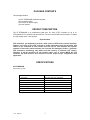
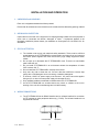
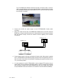
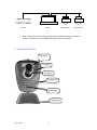
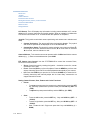
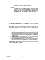
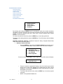
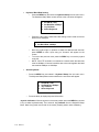
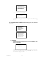
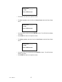
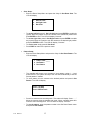
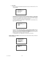
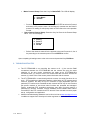
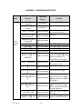
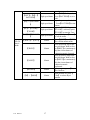
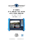
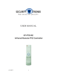
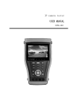
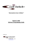
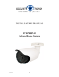
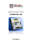
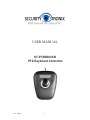
USER MANUAL ST-PTZMINI-KB PTZ Keyboard Controller v1.0 6/21/11 1 TABLE OF CONTENTS PACKAGE CONTENTS....................................................................................................3 PRODUCT DESCRIPTION ...............................................................................................3 SPECIFICATIONS ...........................................................................................................3 INSTALLATION AND OPERATION ..................................................................................4 1. UNPACKING and HANDLING ....................................................................................................................... 4 2. MECHANICAL INSPECTION.......................................................................................................................... 4 3. SPECIAL ATTENTION .................................................................................................................................... 4 4. WIRING CONNECTIONS ................................................................................................................................ 4 5. KEYBOARD OPERATION .............................................................................................................................. 6 KEYBOARD OPERATION: ................................................................................................................................................. 7 LCD Screen Joystick Camera Address PTZ Camera Lens Control Setting Preset Scan, Pattern, Cruise Functions Call Camera Main Menu Matrix Control Change Monitor KEYBOARD MENU CONTROL: ........................................................................................................................................ 9 Parameter Setup Joystick Calibration Camera Setup Camera Scan Setup Camera Pattern Setup Camera Tour Setup Protocol Setup Pelco Matrix Model Setup 6. TROUBLESHOOTING TIPS ........................................................................................................................ 15 APPENDIX 1: KEYBOARD SHORTCUTS.........................................................................16 APPENDIX 2: MENU TREE ...........................................................................................18 v1.0 6/21/11 2 PACKAGE CONTENTS This package contains: One ST-PTZMINI-KB keyboard controller One connection block One 12VDC 2A power supply One user manual PRODUCT DESCRIPTION The ST-PTZMINI-KB is a professional grade pan, tilt, zoom (PTZ) controller for up to 31 PTZ-enabled CCTV cameras and other devices. The unit uses RS-485 communications, includes an LCD display and a 3-axis joystick. Important Note PTZ controllers are designed to perform a wide variety of PTZ camera control functions. However, the utility of any PTZ controller is highly dependant upon the particular PTZ camera to be controlled as each camera has not only its own functions but specific methods of how those native functions are accessed and managed. Further, a particular PTZ controller’s terminology may differ from that used by a particular PTZ camera. Therefore, it will be necessary for the installer and/or user to consult BOTH the PTZ controller and PTZ camera’s user manuals to ensure proper set-up, configuration and application. SPECIFICATIONS ST-PTZMINI-KB Specifications (Typical) v1.0 1. Communications Protocol RS-485 2. Baud Rate 2400, 4800, 9600, and 19200 Bits/S 3. Transmitting Distance 3900 feet using 24AWG twisted pair cable 4. Operating Temperature 32°F - 122°F 5. Relative Humidity <90% 6. Power Supply 12VDC 2A 7. Dimensions 6.6”x5.4”x4.1” 8. Weight 14 oz. 6/21/11 3 INSTALLATION AND OPERATION 1. UNPACKING and HANDLING Each unit is shipped assembled and factory tested. Ensure that all accessories are removed from the container before discarding packing material 2. MECHANICAL INSPECTION Inspect the front and rear of the equipment for shipping damage. Make sure the equipment is clean, and no connectors are broken, damaged, or loose. If equipment appears to be damaged or defective please contact your distributor or Securitytronix at 1-610-429-1511 for assistance. 3. SPECIAL ATTENTION a. The installer must comply with electrical safety standards. There must be sufficient space between the ST-PTZMINI-KB’s communication and power lines and camera’s and DVR’s power supplies and video lines and any high voltage equipment and/or cables. b. Do not open up or dismantle the ST-PTZMINI-KB’s case. There are no serviceable parts inside the unit. c. Do not install ST-PTZMINI-KB in an environment where the temperature is below 32ºF or above 122° F. d. Do not install the ST-PTZMINI-KB in a damp environment. e. Only use a dry cloth to clean the unit. If there is dirt that is difficult to remove wipe gently with a mild detergent. Never use strong or abrasive detergents. f. A minimum 12VDC 2A power supply must be used. AC power cannot be applied. Using an AC or other incorrect power supply will damage the unit. g. Only qualified installers are allowed to install and test the ST-PTZMINI-KB. h. As the ST-PTZMINI-KB is a sensitive device any shock or collision to the unit or shaking of the unit will cause damage and void the warranty. 4. WIRING CONNECTIONS a. The ST-PTZMINI-KB has an RS485 interface and an infrared interface for connection to PTZ cameras or other peripheral devices (e.g., DVRs). The infrared interface is not supported at this time. Power/RS485 v1.0 6/21/11 4 IR emitter The ST-PTZMINI-KB’s RS485 interface and power connection share a common cable connected directly to the unit as depicted below. A terminal block for wiring UTP (unshielded twisted pair) cable between the PTZ camera or other device and the controller is included. b. Connect the 12VDC 2A power supply to the ST-PTZMINI-KB’s female power connector. c. Using UTP cable connect the ST-PTZMINI-KB’s RS485 port to the PTZ camera’s RS485 port. Using the terminal block be sure the polarities are correct and consistent with the camera. Always consult the camera’s manual regarding PTZ controller connections. Camera A+ BRS485 A+ B- d. Connect power supply’s AC plug to a suitable AC power outlet. When power is applied the ST-PTZMINI-KB will automatically display the baud rate and keyboard protocol on the LCD screen. Note: When the controller is initializing the joystick should be in the “nil” (0 or neutral) position. e. It is also possible for the ST-PTZMINI-KB to control multiple PTZ cameras using a matrix switch in lieu of a DVR per the diagram below. The PTZ controller and cameras are connected in parallel to the matrix’s RS485 buss. Be sure to assign each camera a unique address and set the cameras’ and controller’s communications at 9600bps. v1.0 6/21/11 5 Controller f. Matrix PTZ Camera 1 Note: If using more than one PTZ controller each controller must have a unique ID. Further, no more than 4 ST-PTZMINI-KBs can be used in one system. 5. KEYBOARD OPERATION LCD Screen Lens Control 3D Joystick Function Keys Number Keys Keypad Cover v1.0 PTZ Camera 2 6/21/11 6 KEYBOARD OPERATION: LCD Screen Joystick Camera Address PTZ Camera Lens Control Setting Preset Scan, Pattern, Cruise Functions Call Camera Main Menu Matrix Control Change Monitor LCD Screen: The LCD displays key information including camera address or ID, monitor address or ID, protocol, baud rate and joystick position. When an operation is initiated the LCD will be lit and remain on for 10 seconds after the operation is completed. Joystick: The joystick controls both camera positioning and camera menu selection and setup. Camera Positioning: The camera will follow the joystick’s direction. The joystick and camera’s position will be displayed on the LCD as Camera Menu Setup: The joystick is used to selection menu items as follows: for the upper menu item, for the next menu item, for a sub menu or save and for cancel, return to submenu or exit. Camera Address: To choose the camera to operate use N + CAM where N is the camera address (e.g., 1). Enter camera address then press CAM. PTZ Camera Lens Control: Use the ST-PTZMINI-KB to control the camera’s Zoom, Focus and Iris lens features. Zoom: Control the zoom by rotating the joystick – clockwise to zoom far, counter clockwise to zoon wide. Focus: Press the FAR key to focus far objects. Press the NEAR key to focus near objects. Normally Zoom and Focus will be adjusted automatically by the camera. Iris: Press the OPEN key to open the iris. Press the CLOSE key to close the Iris. Pressing these keys will manually adjust the iris. Note: Many cameras do not support manual iris control. Setting Camera Presets, Scan, Pattern and Cruise Functions: Preset: o To create a preset move the camera to the desired point, press the SET key, the N key (where N is the preset number) and the PRE key (SET + N + PRE). o To adjust the preset press the N key and the PRE key (N + PRE). v1.0 6/21/11 Scan: o To set the left border, press the SET key, 1 key and SCAN key (SET + 1 + SCAN). o To set the right border, press the SET key, 2 key and SCAN key (SET + 2 + SCAN). o Start: To start the Left – Right scan press the 1 key and SCAN key (1 + SCAN). 7 o Enter the camera’s menu to change the scan speed. Pattern: o To create a pattern press the SET key, the N key (where N is the number to designate a pattern scan), the PATTERN key then direct the camera along the path for the pattern the press the SET key, the 0 key then the PATTERN key (SET + N + PATTERN + camera path + SET + 0 + PATTERN). Note: up to 4 patterns can be created and stored (N will be designated 1, 2, 3, or 4). o To start a pattern scan, input the pattern number 1, 2, 3 or 4 then press the PATTERN key to commence scanning. (enter 1, 2, 3, or 4, + PATTERN). Tour: o o To start a cruise press the N key, then the TOUR key. N represents the desired tour number and TOUR will start the cruise (N + TOUR). If only one cruise has been created then simply press the TOUR key. Call The Camera’s Main Menu: Press 9 + 5 + PRESET. The camera’s menu will be displayed on the monitor. Matrix Control: A matrix can support a specific number of PTZ cameras. The ST-PTZMINI-KB can support up to 16 PTZ cameras in a matrix. All camera information such as address, data, and time will be displayed when switching from one camera to another. Note: the user should refer to the matrix switch’s manual regarding the matrix’s specific features, functions and limitations. Switch Camera Order: Press the PREV key to switch back to the previous camera. Pressing and holding the PREV key for 2 seconds will allow switching backwards through all cameras. Press the STOP key to stop switching. Press the NEXT key to advance to the next camera. Pressing and holding the NEXT key for 2 seconds will allow switching forwards through all cameras. Use the STOP key to stop the switching. Call Matrix Main Menu: To call the matrix switch menu press the SHIFT and SET keys (SHIFT + SET). The menu will be displayed on the monitor. Confirm Matrix Programming: Refer to the matrix switch’s manual regarding how to program the matrix. Press the ENTER key to confirm a program setting. Change Monitor: To change image to a different monitor press the N key (where N is the monitor ID) and the MON key (N + MON). v1.0 6/21/11 8 KEYBOARD MENU CONTROL: Parameter Setup Joystick Calibration Camera Setup Camera Scan Setup Camera Pattern Setup Camera Tour Setup Protocol Setup Pelco Matrix Model Setup 1. 2. 3. 4. Keyboard Setup Dome Setup Protocol Select Exit Menu By pressing and holding the MENU key for 2 seconds the main menu screen (as above) will appear. The user must enter the main menu and either use the menu item number or joystick to select the desired menu item. Once done, move the joystick right or press ENTER to enter that menu. To move to a previous menu item press the PREV key or move the joystick left. To save a menu setting selection press the ENTER key. The LCD screen will then display “Success”. Keyboard Parameter Settings: Keyboard Camera ID Setup; Keyboard Baud Rate Setup; Keyboard Information Display. Keyboard Camera ID Setup: o Press the MENU key and select 1. Keyboard Setup from the main menu. The Keyboard Setup Menu screen similar to the one below will appear. 1. 2. 3. 4. Set KB ID (1-64): Set Baudrate: 2400bps Joy Calibrate About Keyboard Press the 1 key for Set KB ID. Press 1 again and the LCD screen will display: 1. Set KB ID (1-64): o o o v1.0 6/21/11 Press 1 to select the keyboard ID setting. Use the numeric keys to select the ID from 1 to 64 (if the selected ID is greater than 64 “Error” will be displayed). Then press the ENTER key to save. Upon doing so “Success” will appear on the screen. To move to the previous menu press the PREV key or move the joystick to the left. NOTE: The keyboard ID default is 1. 9 Keyboard Baud Rate Setting: o Press the MENU key and select 1. Keyboard Setup from the main menu. The Keyboard Setup Menu screen similar to the one below will appear. 1. 2. 3. 4. o Set KB ID (1-64): Set Baudrate: 2400bps Joy Calibrate About Keyboard Press the 2 key and the select baud rate setting screen similar to the one below will be displayed. 2. Set Baud Rate: 2400bps o o o Move the joystick right or up/down to select the desired baud rate then press ENTER to save. Upon doing so “Success” will appear on the screen. To move to the previous menu press the PREV key or move the joystick to the left. NOTE: If the PTZ controller is connected to a matrix switch the baud rate must be 9600bps. If several controllers are to be used together the baud rate must be 9600bps or 19200bps. About Keyboard: o Press the MENU key and select 1. Keyboard Setup from the main menu. The Keyboard Setup Menu screen similar to the one below will appear. 1. 2. 3. 4. o Set KB ID (1-64): Set Baudrate: 2400bps Joy Calibrate About Keyboard Press the 4 key to display keyboard information. Joystick Calibration: With the joystick in the center position press the MENU key and the 1 key to select keyboard setup. Then select 3. Joy Calibrate from the Keyboard Setup Menu. Note: the joystick must remain in the center (neutral) position when calibrating. v1.0 6/21/11 10 1. 2. 3. 4. o Set KB ID (1-64): Set Baudrate: 2400bps Joy Calibrate About Keyboard Press the 3 key. The LCD will display: Joystick is free then press ENTER o Press ENTER and the joystick calibration is completed. The LCD will display “Success”. PTZ Dome Camera Setup: Press MENU to enter the main menu then press the 2 key to enter the Dome Setup Menu. This menu will allow the setting of preset, scan, pattern and tour functions. 1. 2. 3. 4. Keyboard Setup Dome Setup Protocol Select Exit Menu 1. 2. 3. 4. Set Dome Preset Set Dome Scan Set Dome Pattern Set Dome Tour Preset Setup: o Press the 1 key to enter the Preset function. The LCD will then display menu options as shown below. 1. Save Preset 2. Show Preset 3. Clear Preset o v1.0 6/21/11 To create and save a preset. press the 1 key then input the preset number, aim the camera to the desired target, then press ENTER to save and confirm. The LCD will then display “Success”. 11 Preset num:________ (1-128) Press PREV to back o Press PREV to return to the previous menu. o To show a preset, press the 2 key for Show Preset under the Dome Setup Menu. Preset num:________ (1-128) Press PREV to back o o o Input the preset number and press ENTER to call it. The LCD will then display “Success”. Press PREV to return to the previous menu. To delete a preset, press the 3 key for Clear Preset under the Dome Setup Menu. Preset num:________ (1-128) Press PREV to back o o v1.0 6/21/11 Input the preset to be cleared and press ENTER to clear it. The LCD will then display “Success”. Press PREV to return to the previous menu. 12 Scan Setup: o Enter the Dome Setup Menu and press the 2 key for Set Dome Scan. The LCD will display: 1. Set Left Limit 2. Set Right Limit 3. Run Scan o o o o To set the left limit, press 1. Set Left Limit and press ENTER to enable the joystick. Move the joystick to aim the camera to the desired left position and press ENTER to save. The LCD will display “Success” To set the right limit, press 2. Set Right Limit and press ENTER to enable the joystick. Move the joystick to aim the camera to the desired right position and press ENTER to save. The LCD will display “Success”. To run the scan simply press 3. Run Scan. Press PREV to return to the previous menu. Pattern Setup: o Enter the Dome Setup Menu and press the 3 key for Set Dome Pattern. The LCD will display: 1. Pattern num:_____ 2. Set Pattern 3. Run Pattern o o The controller will support up to 4 patterns. Input pattern number 1 – 4 and press ENTER. The system will skip to the next item automatically to set the second pattern if needed. To set a pattern, aim the camera to the desired position and press 2. Set Pattern. The LCD will display: Press 1 to Start Press 0 to Stop Press PREV to back o o v1.0 6/21/11 Press 1 to start the scan recording track. The screen will display “Start ……,” Move the camera along the desired scan track. When completed press 0 to finish the scan recording track. The LCD will then display “Success”. To run the pattern, enter the pattern number in the Set Dome Pattern menu and press 3. Run Pattern. 13 Tour Setup: o Enter the Dome Setup Menu and press the 4 key for Set Dome Tour. The LCD will display: 1. Tour num:______ 2. Insert Preset 3. Run Tour o o The controller will support up to 6 tours. Input tour number 1 – 6 and press ENTER to confirm. The system will skip to the next item automatically to set the second tour if needed. If not, the user can skip it and the LCD will display “Success”. The system will return to the previous menu. To enter presets for the tour press 2. Insert Preset in the Set Dome Tour Menu. The LCD will display: 1. Preset num:______ 2. Speed : 3. Dwell : o o Press 1 to enter the preset number. Press 2 to enter the speed using the range of 1 – 127. Press 3 to enter the dwell time using the range of 1 – 255. After entering all the above parameters press ENTER to save. The LCD will display “Success” and return to the previous menu. To run the tour, press 3. Run Tour in the Set Dome Tour Menu. Protocol Setup: Press MENU to enter the main menu then press the 3 key to enter the Protocol Setup Menu. 1. 2. 3. 4. Keyboard Setup Dome Setup Protocol Select Exit Menu 1. Matrix/DVR 2. Dome v1.0 6/21/11 14 Matrix Protocol Setup: Press the 1 key for Matrix/DVR. The LCD will display: 1. Pelco Matrix 2. DH DVR Press the 1 key to select Pelco Matrix the press ENTER to select the Protocol and return to the previous menu. All Securitytronix cameras use the Pelco-D protocol. For setting of a third party matrix or DVR refer to the unit’s operation manual. Dome Camera Protocol Setup: Press the 2 key for Dome in the Protocol Setup Menu. The LCD will display: o 1. 2. 3. 4. o Factory Pelco-P Pelco-D DH-SD Refer to the camera’s manual for the protocol to be used. Press the 1, 2 or 3 key according to the camera’s protocol. Press ENTER to confirm. Upon completing all settings return to the main menu and press the 5 key Exit Menu. 6. TROUBLESHOOTING TIPS a. The ST-PTZMINI-KB is not controlling the camera at all – (i) be sure the R485 connections between the ST-PTZMINI-KB and the camera are using the same polarities; (ii) be sure correct connections are made at the ST-PTZMINI-KB’s connection block; (iii) check to see if the correct baud rate has been set with the camera; (iv) check to see if the correct protocol has been with the camera. b. The ST-PTZMINI-KB is communicating with the camera, but certain functions do not work – PTZ controllers are designed to perform a wide variety of PTZ camera control functions. However, the utility of any PTZ controller is highly dependant upon the particular PTZ camera to be controlled as each camera has not only its own functions but specific methods of how those native functions are accessed and managed. Further, a particular PTZ controller’s terminology may differ from that used by a particular PTZ camera. Therefore, it will be necessary for the installer and/or user to consult BOTH the PTZ controller and PTZ camera’s user manuals to ensure proper set-up, configuration and application. c. v1.0 Additional troubleshooting assistance can be found on-line at www.securitytronix.com in addition to support from Securitytronix sales engineers at 1-610-429-1511. 6/21/11 15 APPENDIX 1: KEYBOARD SHORTCUTS Working Mode Shortcut Press【SET】for 2 seconds Press 【MENU】for 2 seconds Direct Control Mode v1.0 6/21/11 Operation Object Keyboard Keyboard 【N】+【CAM】 High speed dome 【Rotate the joystick anti-clockwise】 High speed dome 【Rotate the joystick clockwise】 High speed dome Function IR remote ON/OFF Enter the system setting Input Dome ID, press【CAM 】to select object dome. Zoom in Zoom out Press【FAR】, far focus Press【NEAR】, near focus Press【CLOSE】, reduce iris Press【OPEN】, increase Iris Adjust the image to object position, Press【SET】to input 【SET】+【N】+【 High speed dome the preset, and press【 PRESET】 PRESET】to set the preset Input preset ID, press【Preset 【N】+ 【PRESET】 High speed dome 】to call the preset ON/OFF water Wiper 【SHI】+【1】+【ENT High speed dome 】 ON/OFF auxiliary light 【SHI】+【2】+【ENT High speed dome 】 Adjust the image to object position, press Set to input【1 【SET】+【1】+【SCAN High speed dome 】,then press Scan to set【scan 】 】left limit. Adjust the image to object 【SET】+【2】+【SCAN position, press Set to input High speed dome 【2】,then press【Scan】to 】 set scan right limit. Input【1】, press【Scan】to 【1】+【SCAN】 High speed dome run scan. Press 【Set】to input pattern High speed dome 【SET】+【N】+【 number, press【Pattern】 to PATTERN】 【FAR】 【NEAR】 【CLOSE】 【OPEN】 High speed dome High speed dome High speed dome High speed dome 16 【SET】+【0】+【 PATTERN】 High speed dome 【N】+【PATTERN 】 High speed dome 【N】+ 【TOUR】/ 【TOUR】 High speed dome 【9】+【5】+【PRESET High speed dome 】 PELCO Matrix Mode v1.0 6/21/11 【SHIFT】+ 【SET】 Matrix 【PREV】 Matrix 【NEXT】 Matrix 【ENTER】 Matrix 【N】+ 【MON】 Matrix 17 record pattern path. Press【SET】 and input0, Press【PATTERN】to save path Input the pattern path(1-4) ,Press【PATTERN】to start pattern Input the TOUR NO, press 【TOUR】 or directly press 【TOUR】to start the Tour Input 95 and press【Preset】 to call the menu Press【SHIFT】and 【SET 】to call the matrix menu Press 【PREV】skip to the previous dome, hold on 2sec on【PREV】to continuously skip the sixteen domes of connection matrix forwards Press 【NEXT】skip to the previous dome, hold on 2sec on【NEXT】to continuously skip the sixteen domes of connection matrix backwards After program, press【Enter 】to confirm.。 Input monitor ID, press【 Cam】 to select object monitor APPENDIX 2: MENU TREE v1.0 6/21/11 18