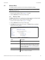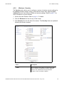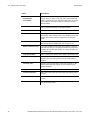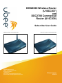
1
DDW2600 Wireless Router (U10CC037) and DDC2700 Commercial Router (U10C038) Subscriber User Guide DDW2600 Wireless Cable Modem/Router www.ubeeinteractive.com 8085 S. Chester Street, Suite 200 Englewood, CO 80112 1.888.390.8233 Sales (email): [email protected] Support (email) [email protected] DDC2700 Commercial Cable Modem/Router Release Version 5/20/10 Notices and Copyrights Copyright © 2010 Ubee. All Rights Reserved. This document contains proprietary information of Ubee and is not to be disclosed or used except in accordance with applicable agreements. This material is protected by the copyright laws of the United States and other countries. It may not be reproduced, distributed, or altered in any fashion by any entity (either internal or external to Ubee), except in accordance with applicable agreements, contracts, or licensing, without the express written consent of Ubee and the business management owner of the material. Contents 1 Safety and Regulatory Information. . . . . . . . . . . . . . . . . . . . . . . . . . . . . . . . . . . . . 1 1.1 1.2 1.3 Safety . . . . . . . . . . . . . . . . . . . . . . . . . . . . . . . . . . . . . . . . . . . . . . . . . . . . . . . . . . . . . Eco-Environmental Statements . . . . . . . . . . . . . . . . . . . . . . . . . . . . . . . . . . . . . . . . . 1.2.1 Packaging Collection and Recovery Requirements: . . . . . . . . . . . . . . . . . . . Regulatory Statements. . . . . . . . . . . . . . . . . . . . . . . . . . . . . . . . . . . . . . . . . . . . . . . . 1.3.1 Industry North America Statement: . . . . . . . . . . . . . . . . . . . . . . . . . . . . . . . . 1.3.2 Radiation Exposure Statement: . . . . . . . . . . . . . . . . . . . . . . . . . . . . . . . . . . . 1 2 2 2 2 2 2 Introduction. . . . . . . . . . . . . . . . . . . . . . . . . . . . . . . . . . . . . . . . . . . . . . . . . . . . . . . . 3 2.1 2.2 2.3 2.4 2.5 2.6 2.7 Application Diagram . . . . . . . . . . . . . . . . . . . . . . . . . . . . . . . . . . . . . . . . . . . . . . . . . . 4 Support. . . . . . . . . . . . . . . . . . . . . . . . . . . . . . . . . . . . . . . . . . . . . . . . . . . . . . . . . . . . 4 Physical Specifications, Standards, Firmware Operations. . . . . . . . . . . . . . . . . . . . . 5 Default Values/Device Logins . . . . . . . . . . . . . . . . . . . . . . . . . . . . . . . . . . . . . . . . . . 7 2.4.1 Wireless Defaults (for DDW2600 only). . . . . . . . . . . . . . . . . . . . . . . . . . . . . . 7 2.4.2 How to Find the MAC Address of the Device . . . . . . . . . . . . . . . . . . . . . . . . . 8 Device Package Components . . . . . . . . . . . . . . . . . . . . . . . . . . . . . . . . . . . . . . . . . . 8 Device Back Panel Description . . . . . . . . . . . . . . . . . . . . . . . . . . . . . . . . . . . . . . . . . 9 2.6.1 DDW2600 and DDC2700 Back Panel Images . . . . . . . . . . . . . . . . . . . . . . . . 9 Device Front Panel & LED Behavior . . . . . . . . . . . . . . . . . . . . . . . . . . . . . . . . . . . . 10 2.7.1 DDW2600 and DDC2700 Front Panel Images. . . . . . . . . . . . . . . . . . . . . . . 10 2.7.2 LED Behavior Table . . . . . . . . . . . . . . . . . . . . . . . . . . . . . . . . . . . . . . . . . . . 11 3 Install the Device . . . . . . . . . . . . . . . . . . . . . . . . . . . . . . . . . . . . . . . . . . . . . . . . . . 13 3.1 3.2 Connect the Device and Access the Web Interface. . . . . . . . . . . . . . . . . . . . . . . . . 3.1.1 Connect the Device . . . . . . . . . . . . . . . . . . . . . . . . . . . . . . . . . . . . . . . . . . . 3.1.2 Access the Web Interface . . . . . . . . . . . . . . . . . . . . . . . . . . . . . . . . . . . . . . Confirm Installation and Connect Devices to the Network . . . . . . . . . . . . . . . . . . . . 3.2.1 DDW2600 Wireless Cable Modem/Router Only. . . . . . . . . . . . . . . . . . . . . . 3.2.2 Additional Troubleshooting Information . . . . . . . . . . . . . . . . . . . . . . . . . . . . 13 13 14 16 16 17 4 Web User Interface Instructions . . . . . . . . . . . . . . . . . . . . . . . . . . . . . . . . . . . . . . 19 4.1 4.2 Modem Menu . . . . . . . . . . . . . . . . . . . . . . . . . . . . . . . . . . . . . . . . . . . . . . . . . . . . . . 4.1.1 Modem - Cable Modem Information . . . . . . . . . . . . . . . . . . . . . . . . . . . . . . . 4.1.2 Modem - Status . . . . . . . . . . . . . . . . . . . . . . . . . . . . . . . . . . . . . . . . . . . . . . 4.1.3 Modem - Downstream . . . . . . . . . . . . . . . . . . . . . . . . . . . . . . . . . . . . . . . . . 4.1.4 Modem - Upstream. . . . . . . . . . . . . . . . . . . . . . . . . . . . . . . . . . . . . . . . . . . . 4.1.5 Modem - Upstream Burst . . . . . . . . . . . . . . . . . . . . . . . . . . . . . . . . . . . . . . . 4.1.6 Modem - Operation Config . . . . . . . . . . . . . . . . . . . . . . . . . . . . . . . . . . . . . . 4.1.7 Event Log . . . . . . . . . . . . . . . . . . . . . . . . . . . . . . . . . . . . . . . . . . . . . . . . . . . Gateway Menu . . . . . . . . . . . . . . . . . . . . . . . . . . . . . . . . . . . . . . . . . . . . . . . . . . . . . 4.2.1 Gateway - Information . . . . . . . . . . . . . . . . . . . . . . . . . . . . . . . . . . . . . . . . . 4.2.2 Gateway - Setup. . . . . . . . . . . . . . . . . . . . . . . . . . . . . . . . . . . . . . . . . . . . . . 4.2.3 Gateway - DHCP . . . . . . . . . . . . . . . . . . . . . . . . . . . . . . . . . . . . . . . . . . . . . DDW2600 Wireless & DDC2700 Commercial Cable Modem/Router Subscriber User Guide • May, 2010 19 19 20 21 22 23 24 24 26 26 28 30 i Ubee Interactive 4.3 4.4 4.5 4.6 4.7 ii 4.2.4 Gateway - DHCP Static Lease . . . . . . . . . . . . . . . . . . . . . . . . . . . . . . . . . . . 4.2.5 Gateway - DDNS . . . . . . . . . . . . . . . . . . . . . . . . . . . . . . . . . . . . . . . . . . . . . 4.2.6 Gateway - Time . . . . . . . . . . . . . . . . . . . . . . . . . . . . . . . . . . . . . . . . . . . . . . 4.2.7 Advanced Gateway Setup - Options . . . . . . . . . . . . . . . . . . . . . . . . . . . . . . 4.2.8 Advanced Gateway Setup - Mac Filtering . . . . . . . . . . . . . . . . . . . . . . . . . . 4.2.9 Advanced Gateway Setup - IP Filtering . . . . . . . . . . . . . . . . . . . . . . . . . . . . 4.2.10 Advanced Gateway Setup - Port Filtering . . . . . . . . . . . . . . . . . . . . . . . . . . 4.2.11 Advanced Gateway Setup - Forwarding. . . . . . . . . . . . . . . . . . . . . . . . . . . . 4.2.12 Additional Information - Forwarding . . . . . . . . . . . . . . . . . . . . . . . . . . . . . . . 4.2.13 Advanced Gateway Setup - Port Triggering . . . . . . . . . . . . . . . . . . . . . . . . . 4.2.14 Additional Information - Port Triggering . . . . . . . . . . . . . . . . . . . . . . . . . . . . 4.2.15 Advanced Gateway Setup - Pass Through . . . . . . . . . . . . . . . . . . . . . . . . . 4.2.16 Advanced Gateway Setup - DMZ Host . . . . . . . . . . . . . . . . . . . . . . . . . . . . Wireless Menu . . . . . . . . . . . . . . . . . . . . . . . . . . . . . . . . . . . . . . . . . . . . . . . . . . . . . 4.3.1 Wireless - Basic . . . . . . . . . . . . . . . . . . . . . . . . . . . . . . . . . . . . . . . . . . . . . . 4.3.2 Wireless - Security . . . . . . . . . . . . . . . . . . . . . . . . . . . . . . . . . . . . . . . . . . . . 4.3.3 Wireless - Access Control . . . . . . . . . . . . . . . . . . . . . . . . . . . . . . . . . . . . . . 4.3.4 Wireless - Guest Network. . . . . . . . . . . . . . . . . . . . . . . . . . . . . . . . . . . . . . . VPN Menu . . . . . . . . . . . . . . . . . . . . . . . . . . . . . . . . . . . . . . . . . . . . . . . . . . . . . . . . 4.4.1 VPN - Enable . . . . . . . . . . . . . . . . . . . . . . . . . . . . . . . . . . . . . . . . . . . . . . . . 4.4.2 VPN - Summary . . . . . . . . . . . . . . . . . . . . . . . . . . . . . . . . . . . . . . . . . . . . . . 4.4.3 VPN - Configure . . . . . . . . . . . . . . . . . . . . . . . . . . . . . . . . . . . . . . . . . . . . . . 4.4.4 VPN Configure - Advanced Settings . . . . . . . . . . . . . . . . . . . . . . . . . . . . . . 4.4.5 VPN - L2TP / PPTP . . . . . . . . . . . . . . . . . . . . . . . . . . . . . . . . . . . . . . . . . . . 4.4.6 Additional information - VPN Overview . . . . . . . . . . . . . . . . . . . . . . . . . . . . 4.4.7 VPN - Event Log. . . . . . . . . . . . . . . . . . . . . . . . . . . . . . . . . . . . . . . . . . . . . . Parental Control Menu . . . . . . . . . . . . . . . . . . . . . . . . . . . . . . . . . . . . . . . . . . . . . . . 4.5.1 Parental Control - User Setup . . . . . . . . . . . . . . . . . . . . . . . . . . . . . . . . . . . 4.5.2 Parental Control - Basic Settings . . . . . . . . . . . . . . . . . . . . . . . . . . . . . . . . . 4.5.3 Parental Control - Tod Filter . . . . . . . . . . . . . . . . . . . . . . . . . . . . . . . . . . . . . 4.5.4 Parental Control - Event Log . . . . . . . . . . . . . . . . . . . . . . . . . . . . . . . . . . . . Firewall Menu. . . . . . . . . . . . . . . . . . . . . . . . . . . . . . . . . . . . . . . . . . . . . . . . . . . . . . 4.6.1 Firewall - Content Filter . . . . . . . . . . . . . . . . . . . . . . . . . . . . . . . . . . . . . . . . 4.6.2 Firewall - Event Log . . . . . . . . . . . . . . . . . . . . . . . . . . . . . . . . . . . . . . . . . . . 4.6.3 Firewall - Remote Log . . . . . . . . . . . . . . . . . . . . . . . . . . . . . . . . . . . . . . . . . Tools Menu . . . . . . . . . . . . . . . . . . . . . . . . . . . . . . . . . . . . . . . . . . . . . . . . . . . . . . . 4.7.1 Tools - Ping . . . . . . . . . . . . . . . . . . . . . . . . . . . . . . . . . . . . . . . . . . . . . . . . . 4.7.2 Tools - Trace Route . . . . . . . . . . . . . . . . . . . . . . . . . . . . . . . . . . . . . . . . . . . 4.7.3 Tools - Client List . . . . . . . . . . . . . . . . . . . . . . . . . . . . . . . . . . . . . . . . . . . . . 4.7.4 Tools - Scanning Plan . . . . . . . . . . . . . . . . . . . . . . . . . . . . . . . . . . . . . . . . . 4.7.5 Tools - Password (Subscriber) . . . . . . . . . . . . . . . . . . . . . . . . . . . . . . . . . . . 4.7.6 Tools - User Defaults . . . . . . . . . . . . . . . . . . . . . . . . . . . . . . . . . . . . . . . . . . 32 33 34 37 38 38 39 41 43 44 46 47 48 49 49 51 55 57 61 61 62 63 67 68 69 70 71 71 73 74 75 76 76 78 78 80 80 81 82 83 84 85 DDW2600 Wireless & DDC2700 Commercial Cable Modem/Router Subscriber User Guide • May, 2010 1 Safety and Regulatory Information The following information provides safety and regulatory standards for anyone installing, maintaining, and using the DDW2600 wireless or the DDM2700 commercial cable modem/router. 1.1 Safety WARNING: The following information provides safety guidelines for anyone installing and maintaining the DDW2600 or DDM2700 router. Read all safety instructions in this guide before attempting to unpack, install, operate, or connect power to this product. Follow all instruction labels on the device itself. Comply with the following safety guidelines for proper operation of the device: Always follow basic safety precautions to reduce the risk of fire, electrical shock and injury. To prevent fire or shock hazard, do not expose the unit to rain, moisture, or install this product near water. Never spill any form of liquid on or into this product. Do not use liquid cleaners or aerosol cleaners on or close to the product. Use a soft dry cloth for cleaning. Do not insert any sharp object into the product’s module openings or empty slots. Doing so may accidentally damage its parts and/or cause electric shock. Electrostatic discharge (ESD) can permanently damage semiconductor devices. Always follow ESD-prevention guidelines for equipment handling and storage. Use only the power adapter supplied with the device. Do not attach the power supply cable on building surfaces or floorings. Do not place heavy objects on top of the device. Rest the power cable freely without any obstacle or heavy items piled on top of it. Refrain from abusing, stepping or walking on the cable. Do not place the device on an unstable stand or table; the device may drop and become damaged. To protect the equipment from overheating, do not block the slots and openings in the module housing that provides ventilation. Do not expose this device to direct sunlight. Do not place any hot devices close to this device, as it may degrade or cause damage to it. DDW2600 Wireless & DDC2700 Commercial Cable Modem/Router Subscriber User Guide • May, 2010 1 1.2 Eco-Environmental Statements 1.2 Ubee Interactive Eco-Environmental Statements The following eco-environmental statements apply to the DDW2600 or DDM2700 router. 1.2.1 Packaging Collection and Recovery Requirements: Countries, states, localities, or other jurisdictions may require that systems be established for the return and/or collection of packaging waste from the consumer, or other end user, or from the waste stream. Additionally, reuse, recovery, and/or recycling targets for the return and/or collection of the packaging waste may be established. For more information regarding collection and recovery of packaging and packaging waste within specific jurisdictions, contact Ubee Interactive at www.ubeeinteractive.com. 1.3 Regulatory Statements The following regulatory statements applies to the DDW2600 or DDM2700 router. 1.3.1 Industry North America Statement: This device complies with RSS-210 of the Industry North America Rules. Operation is subject to the following two conditions: (1) This device may not cause harmful interference, and (2) this device must accept any interference received, including interference that may cause undesired operation. 1.3.2 Radiation Exposure Statement: This equipment complies with IC radiation exposure limits set forth for an uncontrolled environment. This equipment should be installed and operated with minimum distance 20cm between the radiator & your body. This device has been designed to operate with an antenna having a maximum gain of 2 dBi. Antenna having a higher gain is strictly prohibited per regulations of Industry North America. The required antenna impedance is 50 ohms. 2 DDW2600 Wireless & DDC2700 Commercial Cable Modem/Router Subscriber User Guide • May, 2010 Ubee Interactive 2 2 Introduction Introduction Welcome to the Ubee family of data networking products! This document provides instructions for anyone who installs, configures, maintains, and uses the Ubee DDW2600 wireless cable modem/router or the DDM2700 commercial cable modem/router. The following topics are also provided: To define all relevant device compliance standards and physical specifications. To provide device installation, user level instructions, and basic troubleshooting. Important: This document can be used for two different Ubee products: the DDW2600 wireless cable modem/router and the DDC2700 commercial cable modem/router. Any instructional differences between the two are noted throughout this document. Ubee recommends that you review this chapter before installing and using the device. To go directly to installing the device, go to page 13. The following topics are provided: Application Diagram (p. 4) Support (p. 4) Physical Specifications, Standards, Firmware Operations (p. 5) Default Values/Device Logins (p. 7) Device Package Components (p. 8) Device Back Panel Description (p. 9) Device Front Panel & LED Behavior (p. 10) DDW2600 Wireless & DDC2700 Commercial Cable Modem/Router Subscriber User Guide • May, 2010 3 2.1 Application Diagram 2.1 Ubee Interactive Application Diagram The diagram below illustrates the general connection topology and uses of the device. Customer Premises Network - Residential or Small Office/Home Office (SOHO) Ubee DDW2600 Wireless Cable Modem/Router Laptops/Other Wireless Devices ... Cable RF/Coax Wi-Fi Clients Wi-Fi Telephone Ubee, or off-the-shelf products can be connected to expand the network (for example, router, wireless router, hub). Subscriber Ethernet Network Extensions To DDC2700 or to DDW2600 (above) ... LAN Ethernet Enabled Devices, PCs, Gaming Consoles, etc. 2.2 Cable RF/Coax RJ45 Ethernet Ubee DDC2700 Commercial Cable Modem/Router Support Subscribers must contact their service provider for direct support. Device documentation support may be available at: http://www.ubeeinteractive.com 4 DDW2600 Wireless & DDC2700 Commercial Cable Modem/Router Subscriber User Guide • May, 2010 Ubee Interactive 2.3 2.3 Physical Specifications, Standards, Firmware Operations Physical Specifications, Standards, Firmware Operations The following list provides the features and specifications of the DDW2600 or DDC2700 cable modem/router: Interfaces Cable: F-Connector, Female LAN: 4 10/100Mbps, Based-T RJ-45 Ports USB: USB 1.0 Port, provides an alternate network connection 32MB DDR Ram Standards/Certifications DOCSIS/Euro DOCSIS 1.0/1.1/2.0 Certified CE/ FCC Class B, UL 60950 RoHS, WEEE IPv4 Wireless: IEEE 802.11; 802.11b/g; DSSS Downstream* Frequency Range: 88 MHz ~ 860MHZ Modulation: 64/256 QAM Maximum Data Rate: 30Mbits/sec (64QAM), 42.8Mbits/sec (256QAM) Symbol Rate: 5.057/5.361/Msymbols/sec RF Input/Output Power: -17 to +15dBmV (64 QAM) -15 to +17dBmV (256 QAM) Input Impedance: 75 Ω Channel Bandwidth: 6 or 8 MHz Upstream* Frequency Range: 5 MHz ~ 42 MHz Modulation: A-TDMA: QPSK 8, 16, 32, 64QAM, S-CMDA: QPSK 8, 16, 32, 64, 128QAM Maximum Data Rate: 0.32 ~ 10.24Mbits (QPSK), 0.64 ~ 20.48Mbits (16QAM), 0.96 ~ 30.72Mbits (64QAM) RF Output Power: A-TDMA: +8dBmV ~ +58dBmV(QPSK), +8dBmV ~ +55dBmV(QAM), +8dBmV ~ +54dBmV (32/64) *Actual speeds can vary based on factors including network configuration, service tier, and network conditions. Wireless (DDW2600 Only) WiFi Multimedia Support WPA, WPS, WEP Encryption 4 SSIDs (1 SSID is Reserved for Service Provider) Transmit Power: 18dBm DDW2600 Wireless & DDC2700 Commercial Cable Modem/Router Subscriber User Guide • May, 2010 5 2.3 Physical Specifications, Standards, Firmware Operations Ubee Interactive Operating Frequency: 2400~2497MHz ISM band Data Rate: 1, 2, 5.5, 6, 9, 11, 12, 24, 36, 48, & 54 Mbps Frequency Range: 11 channels (2.412 to 2.462GHz) Antenna: External, detachable Security Firewall, Stateful Packet Inspection (SPI) MAC/IP/Port Filtering TACACS/RADUIS Authentication DoS (Denial of Services) Detection/Prevention Parental Control: Add/Remove Users, Time Access Rules Network NAT, DMZ, RIP, DHCP Client/Server, Static IP Network Assignment, Multiple Subnet Support Dynamic DNS VPN Pass-Through and VPN End-Point Support (IPSec/L2TP/PPTP) Port Forwarding, Port Filtering, Port Triggering RIP v1, v2 Ethernet 10/100 BaseT, Full-Duplex Auto-Negotiate Functionality, IPv4 Support Device Management Power Saving Features/Management DOCSIS and Web Interface Configuration, Local and Remote Telnet Remote Management Firmware Upgrade via TFTP SNMP v1/v2/v2c Agent Built-In Physical and Environmental 6 DDC2700: 196 x 137 x 32 (W x D x H mm) DDC2600: Same dimensions as DDC2700, includes detachable antenna Power Consumption: Maximum 8W Power Supply: 12V @ 1.0A Input Power: 100 ~ 240VAC, 50 ~ 60Hz Operating Temp.: 0˚C to 40˚C (32˚F to 104˚F) Humidity: 5 ~ 95% (non-condensing) DDW2600 Wireless & DDC2700 Commercial Cable Modem/Router Subscriber User Guide • May, 2010 Ubee Interactive 2.4 2.4 Default Values/Device Logins Default Values/Device Logins This device is pre-configured with the following parameters: Local Port Address: 192.168.0.1, Web Interface: http://192.168.0.1 Operation Mode: NAT Mode (WAN setting) Subnet Mask: 255.255.255.0 Web/Device Interface Logins: Subscriber Username: user Password: user 2.4.1 Wireless Defaults (for DDW2600 only) When initially connecting a wireless client to the wireless device (for example, a PC), the following default values are used: SSID (System Set Identifier): The SSID is what the wireless device uses to advertise itself. The SSID is equal to the last 4 characters of the Cable RF MAC address. Example: If MAC Address is: 00028A1A345 SSID is: A345 Note: Refer to page 8 to find the MAC address of the device. Encryption Key: The device uses 128-bit WEP encryption by default. The WEP key is a 26 digit HEX value. This value is equal to the device MAC address plus 14 zero’s (all lower case without the colons). Example: 00028A1A345600000000000000 (MAC address + 14 Zero’s) Broadcast Channel: The default broadcast channel is 1. DDW2600 Wireless & DDC2700 Commercial Cable Modem/Router Subscriber User Guide • May, 2010 7 2.4.2 How to Find the MAC Address of the Device 2.4.2 Ubee Interactive How to Find the MAC Address of the Device Use one of the following options to find the MAC address of the device: Option 1: Look on the bottom of the device for the Cable RF MAC Address. Option 2: Access the device web interface and find the MAC address in the opening screen, (the Cable Modem Information screen). To access the web interface, refer to page 13. 2.5 Device Package Components The package for the DDW2600 wireless cable modem/router or the DDM2700 commercial cable modem/router contains the following items: Item Description DDW2600 DDW2600 wireless cable modem/router or the DDM2700 commercial cable modem/router DDM2700 RJ-45 * RJ-45 Cable Length ~ 6.0 ft RoHS & UL compliant AC Adapter Vin = 230V 50Hz Vout = 12V; 1.5A Example: Actual appearance subject to change. USB Cable and Driver CD (not shown). Drivers are also available at: www.ubeeinteractive.com 8 DDW2600 Wireless & DDC2700 Commercial Cable Modem/Router Subscriber User Guide • May, 2010 Ubee Interactive 2.6 2.6 Device Back Panel Description Device Back Panel Description Review the images below and the descriptions that follow for an explanation of the device back panel. 2.6.1 DDW2600 and DDC2700 Back Panel Images DDW2600 DDC2700 Back Panel Item/Number 1 - Power Inlet Description The power inlet is used for connecting the device’s power adapter to the device. WARNING: Use only the power adapter shipped with this device. Failure to do so may cause damage to the device. 2 - Reset The reset switch restores the default settings of the device including wireless (DDW2600 only) and custom gateway settings. Use a pointed object to push down on the reset button for 5 seconds (until power LED turns off). After the power LED turns off, release the button. 3 - Ethernet 1 to 4 Ports These four RJ45 Ethernet ports are used to connect Ethernet devices, such as computers and gaming consoles, to the internet. 4 - USB Port Using the USB cable included in the product package, subscribers can connect a device to the network using this port, as long as the device also has a USB port. This may be useful for devices that do not have an ethernet network adapter/port. 5 - Cable Port The Cable port is where the device connects to the cable wall outlet, or a cable splitter connected to the wall outlet. DDW2600 Wireless & DDC2700 Commercial Cable Modem/Router Subscriber User Guide • May, 2010 9 2.7 Device Front Panel & LED Behavior 2.7 Ubee Interactive Device Front Panel & LED Behavior This section describes what the device LEDs indicate on the front panel of the DDW2600 wireless cable modem/router or the DDM2700 commercial cable modem/router. Review the device images below and the LED table on the following page. 2.7.1 DDW2600 and DDC2700 Front Panel Images DDW2600 DDC2700 10 DDW2600 Wireless & DDC2700 Commercial Cable Modem/Router Subscriber User Guide • May, 2010 Ubee Interactive 2.7.2 LED Behavior Table 2.7.2 LED Behavior Table The following table describes what the device LEDs indicate. Note: The WLAN LED is available on the DDW2600 only. LED Label: Power USB Host Sync Ready WLAN Eth-1 Color Green Green Green Green Green Green/Orange Green/Orange Green/Orange Green/Orange driver init. On Flash then Off Flash then Off Flash then Off Off Flash then Off Flash then Off Flash then Off Flash then Off DS Scanning On Slow Flash Off On DS Locked On Slow Flash Off On US Ranging On On Slow Flash On US Ranged On On Slow Flash On IP Init. and On Registration On Fast Flash On CM Initialization CM Operation Network Access Enabled On Depends on Ethernet On Status, On if Connected Network Access Disabled On On Off On On Normal Operations, Cable Interface Traffic, Network Access Enabled On On On On On Eth-2 Eth-3 Eth-4 Depends on Ethernet Status, On if Connected Depends on Ethernet Status, On if Connected Depends on Ethernet Status, On if Connected On, if On, if Connected at Connected at 100Mbps, 100Mbps, Orange if Orange if Connected at Connected at 10Mbps 10Mbps On, if Connected at 100Mbps, Orange if Connected at 10Mbps On, if Connected at 100Mbps, Orange if Connected at 10Mbps Depends on Ethernet Status, On if Connected USB/WLAN/ On Ethernet Connected On, if Connected On, if Connected USB/WLAN/ On Ethernet Traffic Slow Flash Slow Flash if Slow Flash Traffic Slow Flash Slow Flash Slow Flash Upgrade In Progress On, if Connected On, if Connected On, if Connected On, if Connected On, if Connected On Slow Flash On On, Slow Flash if Traffic DDW2600 Wireless & DDC2700 Commercial Cable Modem/Router Subscriber User Guide • May, 2010 11 2.7.2 LED Behavior Table 12 Ubee Interactive DDW2600 Wireless & DDC2700 Commercial Cable Modem/Router Subscriber User Guide • May, 2010 3 Install the Device This chapter explains how to install the DDW2600 wireless cable modem/router or the DDM2700 commercial cable modem/router. 3.1 Connect the Device and Access the Web Interface Use the instructions in this section to connect the device and access the web user interface to configure initial settings. 3.1.1 Connect the Device Complete the following steps to connect the DDW2600 wireless cable modem/router or the DDM2700 commercial cable modem/router. 1. Important: Subscribers must contact their service provider to enable internet access. Typically, the service provider initially connects and configures the device. These steps are also provided below. If you wish to confirm the setup, or add devices to your network, refer to Confirm Installation and Connect Devices to the Network, on page 16. 2. Remove all contents from the device packaging. Place the DDW2600 or DDM2700 in an optimal location for connection to other devices, such as PCs or gaming consoles. Keep the following in mind: For the DDW2600 Wireless Cable Modem Only: Keep the wireless cable modem and wireless clients in open areas or far away from transformers, heavy-duty motors, microwave ovens, refrigerators, fluorescent lights, and other manufacturing equipment. These items can impact wireless signals. A wireless signal may become weaker after it has passed through metal, concrete, brick, walls, or floors. For the DDW2600 and DDM2700: Place the device in a location that has an operating temperature of 0˚C to 40˚C (32˚F to 104˚F). Refer to page 1 for more safety information. 3. Have a PC available and powered on. The PC must have an Ethernet network adapter/Ethernet port. The PC must also have an internet browser installed (for example, Netscape or Internet Explorer). The following are supported: For Windows 2000, XP, Vista: Firefox 1.07 and higher, Internet Explorer v7 and above, Netscape For MAC OS X, 10.2, and higher: Firefox 1.07 and higher, Safari 1.x and higher 4. Connect the power adapter that is included with the product package to the cable modem and to the power outlet. 5. Connect one end of a network cable (supplied in the product package) to your computer’s Ethernet port. Connect the other end to one of the Ethernet ports (for example, Ethernet 1) on the cable modem. 6. Connect a coaxial cable from the Cable port on the device to the cable wall outlet. DDW2600 Wireless & DDC2700 Commercial Cable Modem/Router Subscriber User Guide • May, 2010 13 3.1.2 Access the Web Interface Ubee Interactive 7. Continue to the following section. 3.1.2 Access the Web Interface Use the following procedure to access the web interface. 1. From the computer, launch an internet browser (for example, Internet Explorer, Netscape, Safari, Firefox). Note: The computer must be connected to an Ethernet port on the cable modem, as explained in the previous section. 2. In the internet browser, enter the following address and press <Enter/Return>: http://192.168.0.1 3. The Cable Modem Information window is displayed. Click the Login link on the left side of the window. 14 DDW2600 Wireless & DDC2700 Commercial Cable Modem/Router Subscriber User Guide • May, 2010 Ubee Interactive 3.1.2 Access the Web Interface 4. Enter the login credentials as shown below. Subscriber Login: Username: user Password: user 5. Accessing the web interface is an initial way to validate the installation. No extra steps are required at this point for a basic LAN and/or wireless network (DDW2600 only). 6. Proceed to page 16 to test network connectivity and/or to add both Ethernet LAN devices and wireless devices (DDW2600 only) to the network. Note: The web interface allows you to customize the configurations and capabilities the device. For full explanation of all web interface functions, refer to page 19. DDW2600 Wireless & DDC2700 Commercial Cable Modem/Router Subscriber User Guide • May, 2010 15 3.2 Confirm Installation and Connect Devices to the Network 3.2 Ubee Interactive Confirm Installation and Connect Devices to the Network To confirm network/internet operations, or to connect an Ethernet device to the network (for example, a computer), do the following: 1. Make sure the Ethernet device is connected to the cable modem. Refer to page 13. 2. Use the device LEDs to confirm operations. The PWR, SYNC, and Ready LEDs are solidly lit in normal operations, as are the Ethernet LEDs that have devices connected to their associated ports. Refer to LED Behavior Table, on page 11 for more detailed information. 3. Open a web browser and go to any web site to validate network connectivity (for example, http://www.wikipedia.org). 4. If the connected device is a gaming console, perform any online task supported by the console (for example, log into gaming server, play online game, download content, etc.). 5. Refer to page 17 for troubleshooting information if needed. 3.2.1 DDW2600 Wireless Cable Modem/Router Only To confirm operations or to connect wireless devices to the network (for example, a laptop computer), do the following: 1. Use the device LEDs to confirm operations. The WLAN LED must be solidly lit. The PWR, SYNC, and Ready LEDs must also be solidly lit in normal operations. Refer to LED Behavior Table, on page 11 for more detailed information. 2. Connect a wireless device to the DDW2600 (for example, a laptop computer). Use the following steps: Access the wireless networking feature on your wireless device. On a Windows computer, for example, double-click the Wireless Networking icon in the system tray (lower-right side of the Windows desktop). Click View Wireless Networks. The DDW2600 is shipped with a default SSID. The SSID is the name of the wireless network broadcast from the DDW2600 so that wireless clients can connect to it. Double-click your SSID in the wireless networks window. The SSID is equal to the last 4 characters of the Cable RF MAC address, which is printed on the bottom of the DDW2600. Example: If MAC Address is: 00028A12345 SSID is: 2345 Enter the Network Key. This value is equal to the device MAC address plus 14 zero’s (all lower case without the colons). Example: 00028A12345600000000000000 (MAC address + 14 Zero’s) 16 DDW2600 Wireless & DDC2700 Commercial Cable Modem/Router Subscriber User Guide • May, 2010 Ubee Interactive 3.2.2 Additional Troubleshooting Information 3. Confirm connectivity by opening a web browser and going to any web site (for example, http://www.wikipedia.org). 4. The SSIDs and Network Keys used to access the wireless network can be changed. Refer to page 49. 3.2.2 Additional Troubleshooting Information Use the following tips for troubleshooting the installation. None of the LEDs are on when I power on the Wireless LAN Cable Modem. Check the connection between the power adapter and the cable modem. Power off cable modem and wait for 5 seconds and power on the modem again. If the problem still exists, there may have a hardware problem. The Ethernet 1, 2, 3, or 4 LED on the cable modem is not lit. Try restarting the computer so that is could re-establish a connection with the cable modem. Check for a resource conflict (Windows users only). To do this: (1) Right-click on the My Computer icon on your desktop and choose Properties. (2) Click the Device Manager tab and look for a yellow exclamation point or red X over the NIC in the Network Adapters field. If you see either one, you may have an IRQ conflict. Refer to the manufacturers documentation or you cable service provider for further assistance. Verify that TCP/IP is the default protocol for your network interface card (NIC). Power cycle the cable modem by removing the power adapter from the electrical outlet and plugging it back in. Wait several minutes for the cable modem to re-establish communications with your cable service provider. General Connectivity Issues: If your PC is connected to a hub or gateway, try connecting the PC directly into an Ethernet port on the cable modem. If you are using a cable splitter, try removing the splitter and connect the cable modem directly to the cable wall outlet. Wait several minutes for the cable modem to re-establish communications with the cable service provider. The Ethernet cable may be damaged. Try another cable. If none of these suggestions work, contact your cable service provider for further assistance. DDW2600 Wireless & DDC2700 Commercial Cable Modem/Router Subscriber User Guide • May, 2010 17 3.2.2 Additional Troubleshooting Information 18 Ubee Interactive DDW2600 Wireless & DDC2700 Commercial Cable Modem/Router Subscriber User Guide • May, 2010 4 Web User Interface Instructions This chapter explains how to use the web interface to configure, monitor, or troubleshoot the DDW2600 wireless cable modem/router or the DDM2700 commercial cable modem/router. Access the web interface. Refer to Access the Web Interface, on page 14. Each web interface option is discussed in the following sections. 4.1 Modem Menu This section explains all options under the Modem menu of the device web user interface. 4.1.1 Modem - Cable Modem Information This section explains how to use the Cable Modem Information screen. This is a read-only screen and it displays the device’s basic software/hardware configuration. 1. Access the web interface. Refer to page 14, if needed. 2. Click the Modem link from the top menu and then the Information link from the left side of the screen. Field explanations are listed below the following screen example. Label Description Cable Modem The current DOCSIS standard of the device. MAC Address The unique Media Access Control (MAC) hardware address of cable modem. Serial Number The unique manufacturer serial number of the device. DDW2600 Wireless & DDC2700 Commercial Cable Modem/Router Subscriber User Guide • May, 2010 19 4.1.2 Modem - Status Ubee Interactive Label Description Boot Code Version The boot software code version of the device. Software Version The general software version of the device. Hardware Version The internal version number that identifies the hardware design. CA Key The device installs a Certificate Authority (CA) key that is transferred from the service provider’s server after the cable modem is authenticated. The key is used to secure communication between the service provider and the cable modem. 4.1.2 Modem - Status This section explains how to use the Status screen of the web interface. This is a read-only screen and it displays the device’s general connection information. 1. Access the web interface. Refer to page 14, if needed. 2. Click the Modem link from the top menu and then the Status link from the left side of the screen. Field explanations are listed below the following screen example. Label 20 Description Acquire Downstream Channel Displays a Downstream channel that the cable modem is trying to lock to and the progress. Connectivity State After initialization, the cable modem is configured by a DHCP server to obtain an IP address. Once successful, the cable modem is Online. The Status column shows the progress and status (Online/Offline). The Comments column displays the reason why cable modem’s connectivity state is not Online. Boot State Shows the registration status of the device. Security If BPI is enabled, the status will displays Enabled. DDW2600 Wireless & DDC2700 Commercial Cable Modem/Router Subscriber User Guide • May, 2010 Ubee Interactive 4.1.3 Modem - Downstream 4.1.3 Modem - Downstream This section explains how to use the Downstream screen of the web interface. The Downstream screen displays detailed information on the device’s connection to downstream channels from the service provider. 1. Access the web interface. Refer to page 14, if needed. 2. Click the Modem link from the top menu and then the Downstream link from the left side of the screen. Field explanations are listed below the following screen example. Label Description Downstream Lock Displays if the cable modem succeeded in locking to a downstream channel (Locked/Not Locked). Downstream Channel ID Displays the downstream channel ID. Downstream Frequency Displays the downstream channel frequency on which the cable modem is scanning. Downstream Modulation Displays the modulation method that’s required for the downstream channel to lock on to by the cable modem. This method is determined by the service provider. Downstream Symbol Rate Displays the symbol rate. The current cable modem downstream symbol rates are: QAM64 is 5056941 sym/sec, QAM256 is 5360537 sym/sec. Downstream Interleave Depth Displays the current cable modem downstream Interleave depth (4/8/16/32/64/128/other). Downstream Power Level Displays the receiver power level after ranging process. Downstream SNR Display the SNR of this downstream channel. Refresh Click this button to refresh the active screen data. DDW2600 Wireless & DDC2700 Commercial Cable Modem/Router Subscriber User Guide • May, 2010 21 4.1.4 Modem - Upstream Ubee Interactive 4.1.4 Modem - Upstream This section explains how to use the Upstream screen of the web interface. The Upstream screen displays detailed information on the device’s connection to upstream channels to the service provider. 1. Access the web interface. Refer to page 14, if needed. 2. Click the Modem link from the top menu and then the Upstream link from the left side of the screen. Field explanations are listed below the following screen example. Label 22 Description Upstream Lock Current cable modem upstream lock status (Locked/Not Locked). Upstream Channel ID Displays the current cable modem upstream channel ID. Upstream Frequency Displays the current cable modem upstream frequency (Hz). Upstream Modulation Displays the current cable modem upstream modulation type (QPSK/ QAM8 /QAM16/ QAM32/ QAM64/ QAM128/ QAM256). Upstream Symbol Rate Displays the symbol rate (Ksym/sec). Upstream Transmit Power Level Displays the current cable modem upstream transmit power (dBmV). Upstream Mini-Slot Size Displays the current cable modem upstream mini-slot size in Timebase Ticks of 6.25. Refresh Click this button to refresh the active screen data. DDW2600 Wireless & DDC2700 Commercial Cable Modem/Router Subscriber User Guide • May, 2010 Ubee Interactive 4.1.5 Modem - Upstream Burst 4.1.5 Modem - Upstream Burst This section explains how to use the Upstream Burst screen of the web interface. The Upstream Burst screen displays detailed information on the device’s upstream data flow to the service provider. 1. Access the web interface. Refer to page 14, if needed. 2. Click the Modem link from the top menu and then the Upstream Burst link from the left side of the screen. Field explanations are listed below the following screen example. Label Description Modulation Type QPSK/16QAM. Differential Encoding On/Off Preamble Length 0-1024 (bits). Preamble Value Offset 0-1022 (bits). FEC Error Correction (T) 0 to 10 (0 implies no FEC. The number of codeword parity bytes is 2*T) FEC Codeword Information Bytes (k) Fixed: 16 to 253 (assuming FEC on). Shortened: 16 to 253 (assuming FEC on) Scrambler Seed 15 bits (Not used if scrambler is off) Maximum Burst Size 0-255 (mini-slots) Guard Time Size 4-255 (symbols) Last Codeword Length Fixed/shortened Scrambler on/off On/Off DDW2600 Wireless & DDC2700 Commercial Cable Modem/Router Subscriber User Guide • May, 2010 23 4.1.6 Modem - Operation Config 4.1.6 Ubee Interactive Modem - Operation Config This section explains how to use the Operation Config screen of the web interface. The Operation Config screen displays general information on the device’s active operational capabilities. 1. Access the web interface. Refer to page 14, if needed. 2. Click the Modem link from the top menu and then the Operation Config link from the left side of the screen. Field explanations are listed below the following screen example. Allowed Label Description Network Access Displays the status of cable modem, Denied means no connectivity is established. Allowed means connectivity is established to Internet. Maximum Downstream Data Rate Displays the maximum downstream data rate. Maximum Upstream Data Rate Displays the maximum upstream data rate. Maximum Upstream Channel Burst Displays the maximum upstream Channel burst Maximum Number of CPEs Displays the maximum number of Ethernet devices that can be connected (LAN side) to access the network/internet at the same time. Modem Capability Displays device attributes that indicate aspects of its throughput and latency. 4.1.7 Event Log This section explains how to use the Event Log screen of the web interface. The Event Log screen displays log information that may be useful to diagnose operational issues with the device. 1. Access the web interface. Refer to page 14, if needed. 2. Click the Event Log link from the left side of the screen. Field explanations are 24 DDW2600 Wireless & DDC2700 Commercial Cable Modem/Router Subscriber User Guide • May, 2010 Ubee Interactive 4.1.7 Event Log listed below the following screen example. Label Description First Time Displays the time of the event. Last Time Displays the last time of the event. Priority Displays the event log severity. Description Displays a detailed description of the event log. Refresh/Clear Log Refreshes the event log record. Click Clear Log to clear the screen. DDW2600 Wireless & DDC2700 Commercial Cable Modem/Router Subscriber User Guide • May, 2010 25 4.2 Gateway Menu 4.2 Ubee Interactive Gateway Menu This chapter explains how to use the Gateway functions of the web interface. The Gateway functions provide the majority of configuration for the device including WAN IP addresses, LAN IP addresses, DHCP, and DDNS. Also, advanced setting like DMZ, MAC filtering, and port forwarding are provided. 4.2.1 Gateway - Information 1. Access the web interface. Refer to page 14, if needed. 2. Click the Gateway link from the top of the screen. Then select Information. 3. The Information fields are defined following this screen example. Label Description Internet Settings 26 Gateway MAC Address Displays the Media Access Control (MAC) address of the cable modem. Internet IP Address Displays the Internet IP address obtained from the service provider. Subnet Mask Displays the subnet mask of the Internet IP address. Default Gateway Displays the default gateway IP address. DNS Displays the DNS server IP address. DHCP Remaining Time Displays the remaining DHCP lease time before expiration DDW2600 Wireless & DDC2700 Commercial Cable Modem/Router Subscriber User Guide • May, 2010 Ubee Interactive 4.2.1 Gateway - Information Label Refresh Description Click to refresh the information. Local Settings Gateway IP Address Displays the local IP address of the LAN interface. Subnet Mask Displays the subnet mask value. DHCP Server Displays the status of the DHCP sever feature (Enabled/Disabled). NAT Displays the status of the NAT feature (Enabled/Disabled). Wireless Status Displays the status of the wireless feature (Enabled/Disabled). Operating Mode Displays what mode the router is working in (Bridge, NAT, Router, or NAT Router). Note: Firewall menu options are not available when the device is in Bridge mode. Firewall options are available only when the device is in NAT, NATRoute, or Route modes. Private IP Range Displays the private IP address assigned to DHCP client. Public IP DHCP Server Range Displays the Public IP DHCP Server Range. Public IP Total Range Displays the Public IP total range. System Up-Time Displays the accumulated time since the last power cycle. DDW2600 Wireless & DDC2700 Commercial Cable Modem/Router Subscriber User Guide • May, 2010 27 4.2.2 Gateway - Setup Ubee Interactive 4.2.2 Gateway - Setup The Setup option allows you to make key network configurations to the device. 1. Access the web interface. Refer to page 14, if needed. 2. Click the Gateway link from the top of the screen. 3. Click Setup from the left side of the screen. The Setup fields are explained following this screen example. Label 28 Description LAN IP Address Defines the local IP address, which will be the default gateway address for all wired LAN hosts that connect to the cable modem. MAC Address Displays the LAN interface’s hardware address. WAN IP Address Displays the current WAN public IP address that is obtained from the service provider. WAN MAC Address Displays the WAN interface’s hardware address. Duration Displays the accumulated time since successfully acquiring a WAN public IP address. Expires Displays the remaining time before the expiration of the WAN IP address, if applicable. Release WAN Lease Click to release the WAN public IP address. Renew WAN Lease Click to renew the WAN IP address. Refresh Click to refresh the status of this page. DDW2600 Wireless & DDC2700 Commercial Cable Modem/Router Subscriber User Guide • May, 2010 Ubee Interactive 4.2.2 Gateway - Setup Label Description WAN Connection Type Select the WAN connection type. For each type, different data entry is required, as explained below: 1. DHCP: The WAN interface is set to be a DHCP client, and the IP address is assigned by the service provider’s DHCP server. For more detailed configuration of the DHCP server on the device, refer to page 30. 2. Static IP: For Static IP, you must manually enter the IP address for the WAN interface. 3. PPTP (DHCP): For Point to Point Tunneling Protocol (PPTP), you must enter a username, password, and the PPTP server’s hostname or IP address. 4. PPTP (Static): For Point to Point Tunneling Protocol Static (PPTP), you must enter the static IP address, IP mask, default gateway, username, password, and the PPTP server’s hostname or IP address. Host Name Enter the host name for the router. This may be required by some service providers. Domain Name Enter the domain for the router. This may be required by some service providers. MTU Size Enter the Maximum Transmission Unit size, which defines the largest size of the packet or frame that the device can transfer (256-1500). If this is not given by the Service Provider, leave it as is using 0 for the default. Apply Click to save all changes made in the screen. DDW2600 Wireless & DDC2700 Commercial Cable Modem/Router Subscriber User Guide • May, 2010 29 4.2.3 Gateway - DHCP Ubee Interactive 4.2.3 Gateway - DHCP The DHCP option allows you to configure DHCP server-specific behavior on the device. 1. Access the web interface. Refer to page 14, if needed. 2. Click the Gateway link from the top of the screen. 3. Click DHCP from the left side of the screen. The DHCP fields are explained following this screen example. Label 30 Description DHCP Server Select Yes to enable or No to disable the DHCP server on the device. If No is selected, all of the static DHCP rules in this screen are ignored. Private Starting Address Define the starting private IP address for the pool of IP addresses that may be used by connecting clients. Private addresses are translated to public IPs in order to be used on the network. Number of CPEs Define the maximum number of Customer Premises equipment (CPE) that can connect to the network, via the cable modem using private IP addresses. This number determines the end of the private IP address range started above. Public Starting Address Define the starting public IP address. Public addresses can be recognized on the network. Number of CPEs Define the maximum number of Customer Premises equipment (CPE) that can connect to the network, via the cable modem. This number determines the end of the public IP address range started above. DDW2600 Wireless & DDC2700 Commercial Cable Modem/Router Subscriber User Guide • May, 2010 Ubee Interactive 4.2.3 Gateway - DHCP Label Description Lease Time Enter the time in minutes between 1 and 71582788. This field defines the DHCP lease time duration. A DHCP user's PC gets an IP address with a lease time. When the lease time expires, the PC must connect to the DHCP server and be reissued another, unused IP address. DHCP Clients This list to shows all DHCP clients currently connected to the cable modem, either via Ethernet link, or via wireless connection (DDW2600 only). Each client is also listed with the following information: MAC Address / IP Address / Subnet Mask Duration / Expires: Duration displays the accumulated time since the client acquired the IP address. Expires is the time until the IP expires and must be recycled. If the IP address is reserved to a certain host, it will show "STATIC IP ADDRESS." Select: Click the Select radio button to reserve the current private IP address to be assigned to this host statically. Apply Click Apply to save all changes. Force Available Click Force Available to activate a selected rule in the DHCP Clients List, and assign the displayed private IP address statically to the connected network client. Note: The Select checkbox must be clicked. DDW2600 Wireless & DDC2700 Commercial Cable Modem/Router Subscriber User Guide • May, 2010 31 4.2.4 Gateway - DHCP Static Lease 4.2.4 Ubee Interactive Gateway - DHCP Static Lease The Static Lease option allows you to assign static IP addresses to clients on your network using the IP addresses acquired through the DHCP server on the cable modem. 1. Access the web interface. Refer to page 14, if needed. 2. Click the Gateway link from the top of the screen. 3. Click Static Lease from the left side of the screen. The Static Lease fields are explained following this screen example. Label 32 Description Index Index number of the each client that connects to your network. MAC Address This field is populated with the MAC address of the client that you may want to assign a static IP address to. IP Address Enter a specific IP address to assign to the specific client/host. Enabled Click Enabled to activate this rule. Clear Click Clear to delete the rule. Apply Click Apply to save all screen changes. DDW2600 Wireless & DDC2700 Commercial Cable Modem/Router Subscriber User Guide • May, 2010 Ubee Interactive 4.2.5 Gateway - DDNS 4.2.5 Gateway - DDNS The Dynamic Domain Name Service (DDNS) option allows you to configure your registered Domain Name with a dynamic IP address. 1. Access the web interface. Refer to page 14, if needed. 2. Click the Gateway link from the top of the screen. 3. Click DDNS from the left side of the screen. The DDNS fields are explained following this screen example. Label Description DDNS Service Select the service provider used for your DDNS Service or Disabled. www. DyDNS.org www.no-ip.com User Name Input your DDNS account username as subscribed to the service provider. Password Enter your password for the above account. Host Name Input the host name, as specified by the DDNS service provider. IP address/Status These fields are automatically populated once the User Name and Password are entered. Apply Click Apply to save all screen changes. Refresh Click to refresh the page. DDW2600 Wireless & DDC2700 Commercial Cable Modem/Router Subscriber User Guide • May, 2010 33 4.2.6 Gateway - Time Ubee Interactive 4.2.6 Gateway - Time The Time option allows you to configure the system time obtained from network servers via Simple Network Time Protocol (SNTP). The device must be reset for any changes to take effect. 1. Access the web interface. Refer to page 14, if needed. 2. Click the Gateway link from the top of the screen. 3. Click Time from the left side of the screen. The Time fields are explained following this screen example. Label 34 Description Enable SNTP Click Yes to enable SNTP (Network Time Protocol). Click No to disable the feature. SNTP is a protocol for synchronizing the clocks of computing devices over networks. Current Time Displays the current system time. System Start Time Displays the accumulated time since system was started. Time Server 1 Defines the Time server IP address or Domain name. Use the one provided, or enter an alternative choice. Time Server 2 Defines the Time server IP address or Domain name. Use the one provided, or enter an alternative choice. Time Server 3 Defines the Time server IP address or Domain name. Use the one provided, or enter an alternative choice. DDW2600 Wireless & DDC2700 Commercial Cable Modem/Router Subscriber User Guide • May, 2010 Ubee Interactive 4.2.6 Gateway - Time Time Zone Offset If needed, define the time zone offset in Hours and Minutes. For example: 8 means GMT + 08, -1 means GMT -01. Apply Click Apply to save all screen changes. Reset Values Click Reset Values to reset the screen to factory defaults. DDW2600 Wireless & DDC2700 Commercial Cable Modem/Router Subscriber User Guide • May, 2010 35 4.2.6 Gateway - Time 36 Ubee Interactive DDW2600 Wireless & DDC2700 Commercial Cable Modem/Router Subscriber User Guide • May, 2010 Ubee Interactive 4.2.7 Advanced Gateway Setup - Options 4.2.7 Advanced Gateway Setup - Options The Options selection allows you to define what networking protocols are enabled or disabled on the device. 1. Access the web interface. Refer to page 14, if needed. 2. Click the Gateway link from the top of the screen. 3. Click Options from the left side of the screen. The Options fields are explained following this screen example. Label Description WAN Blocking Select Enable to block connection requests initialized from Internet users. Ipsec PassThrough (Enabled by default) If Internet users initialize an IPSec VPN request to a host located behind the router, NAT makes this attempt fail. Select Enable to force the router to redirect the IPSec request to the local host. PPTP PassThrough (Enabled by default) If Internet users initialize a PPTP VPN request to a host located behind the router, NAT will make this attempt fail. Select Enable to force the router to redirect the PPTP request to the local host. Multicast Enable Multicast optimizes the bandwidth utilization compared with unicast especially video streaming applications. Select Enable to enable multicast. UPnP Enable Select Enable to activate Universal Plug and Play (UPnP). A UPnP device can dynamically join a network, obtain an IP address, convey its capabilities, and learn about other devices on the network. In turn, a device can leave a network smoothly and automatically when it is no longer in use. Apply Click Apply to save all screen changes. DDW2600 Wireless & DDC2700 Commercial Cable Modem/Router Subscriber User Guide • May, 2010 37 4.2.8 Advanced Gateway Setup - Mac Filtering 4.2.8 Ubee Interactive Advanced Gateway Setup - Mac Filtering The MAC Filtering option allows you to filter MAC addresses in order to block internet traffic from specific network devices on the LAN. This filtering establishes a black list. Any host listed on this list will not be able to access the network/internet through the cable modem. 1. Access the web interface. Refer to page 14, if needed. 2. Click the Gateway link from the top of the screen. 3. Click MAC Filtering from the left side of the screen. The MAC Filtering fields are explained following this screen example. Label 4.2.9 Description Index The Index number of the rule. MAC Address Enter the MAC address to block. Clear Select Clear to delete the filtering rule. View Additional Rules: Select from the pull-down to display the remaining 10 rules, if they exist. 20 rules total are supported. Apply Click Apply to save all screen changes. Advanced Gateway Setup - IP Filtering The IP Filtering option allows you to filter IP addresses in order to block internet traffic to specific network devices on the LAN. Any host listed on this list will not be accessible to internet traffic. 1. Access the web interface. Refer to page 14, if needed. 2. Click the Gateway link from the top of the screen. 38 DDW2600 Wireless & DDC2700 Commercial Cable Modem/Router Subscriber User Guide • May, 2010 Ubee Interactive 4.2.10 Advanced Gateway Setup - Port Filtering 3. Click IP Filtering from the left side of the screen. The IP Filtering fields are explained following this screen example. Label Description Start Address Enter the start IP address. End Address Enter the end IP address. Enabled Select Enabled to activate the rule. Apply Click Apply to save all screen changes. 4.2.10 Advanced Gateway Setup - Port Filtering The Port Filtering option allows you to configure port filters in order to block specific internet services on specific ports to all devices on the LAN. 1. Access the web interface. Refer to page 14, if needed. 2. Click the Gateway link from the top of the screen. 3. Click Port Filtering from the left side of the screen. The Port Filtering fields are DDW2600 Wireless & DDC2700 Commercial Cable Modem/Router Subscriber User Guide • May, 2010 39 4.2.10 Advanced Gateway Setup - Port Filtering Ubee Interactive explained following this screen example. Label 40 Description Start Port Enter the start port. End Port Enter the end port. Protocol Select the protocol type, or select Both for UDP and TCP. Enabled Select Enabled to activate the rule and filter out all traffic on the specified ports. Apply Click Apply to save all screen changes. DDW2600 Wireless & DDC2700 Commercial Cable Modem/Router Subscriber User Guide • May, 2010 Ubee Interactive 4.2.11 Advanced Gateway Setup - Forwarding 4.2.11 Advanced Gateway Setup - Forwarding The Forwarding option allows you to configure incoming requests on specific port numbers to reach your internal servers such as web servers, FTP servers, mail servers, gaming consoles, and others, so they can be accessible from the public internet. Note: If your host system(s) do not have communications issues with the internet, Forwarding is not typically needed. 4.2.11.1 Overview, Recommendations, Examples When setting up forwarding, you are recommended to assign a static IP lease to the client/host for which you are setting up forwarding. This way, the IP does not change and disrupt your forwarding rules. For example, if you are hosting a telnet server in your internal network and you wish to setup a forwarding rule for it, you should assign a static IP lease to that system to keep the IP from renewing and disrupting the forwarding rule. The following tasks are recommended to support the setup of forwarding rules: Tools - Client List, on page 82 — Use this option to obtain the MAC and IP address of the internal host for which you are setting up a forwarding rule. You will need these for the following step. Gateway - DHCP Static Lease, on page 32 — Use this option to setup the static lease for the internal network host. Refer to page 43 for more detailed information on Forwarding. To setup forwarding, use the following procedure: 1. Access the web interface. Refer to page 14, if needed. 2. Click the Gateway link from the top of the screen. 3. Click Forwarding from the left side of the screen. Example: The following screen example shows how to setup an XBOX running Modern Warfare 2. Since multiple ports are used for XBOX, separate forwarding rules are setup for each port. The XBOX IP is entered in the Local IP field. The ports used by the XBOX are defined in the Internal Port field. The ports used by XBOX are also defined in the External Port Start and End fields. This configuration now allows the XBOX to receive data from the internet. For detailed information on port forwarding, including how to set it up for specific applications using specific network devices (for example, cable modems), refer to: http://portforward.com DDW2600 Wireless & DDC2700 Commercial Cable Modem/Router Subscriber User Guide • May, 2010 41 4.2.11 Advanced Gateway Setup - Forwarding Ubee Interactive For additional information, consult your host device’s or specific application’s user manual. Label 42 Description Index Displays the Index number of the rule. Local IP Enter the last digits of the IP address of the server for which to setup the forwarding rule. Internal Port Enter the port number listened to by the server host located in your LAN. Public Interface IP Normally, this field is not modified unless you wish to designate another router on the network to forward data through. Ext. Start Port Define the port number to start the range of ports to publish to the Internet. Ext. End Port Define the port number to end the range of ports published to Internet. Note: Be very careful with ranges. Ports within a range will not be usable by other applications that may require them. It is common and safer to enter the same port number as the start and end of the range. Protocol Select the protocol type, UDP, TCPIP, or Both. Enabled Select to enable this rule. Apply Click to save. Port Map Click to show a list of common applications and their ports. DDW2600 Wireless & DDC2700 Commercial Cable Modem/Router Subscriber User Guide • May, 2010 Ubee Interactive 4.2.12 Additional Information - Forwarding 4.2.12 Additional Information - Forwarding Internal Ports are the ports that local servers listen to. External Ports are the ports that the cable modem listens to. For example, a local user on your network (e.g. John) is running a Telnet Daemon on port 64623; the internal port is 64623, the external port is 23. If an internet user initializes a Telnet connection request to this router’s public IP address, the router recognizes that this is a Telnet connection request to a station. According to existing forwarding rules, the router first translates the packet’s destination port to be 64623, and then forward this request to John’s Telnet host. In summary, when you have port forwarding rules set up, your router takes the data off of the external IP address:port number and sends that data to an internal IP address:port number. Port Forwarding rules are created per port. So a rule set up for port 53 will only work for port 53. A port can only be used by one program at a time. DDW2600 Wireless & DDC2700 Commercial Cable Modem/Router Subscriber User Guide • May, 2010 43 4.2.13 Advanced Gateway Setup - Port Triggering 4.2.13 Ubee Interactive Advanced Gateway Setup - Port Triggering The Port Triggering option allows you to configure dynamic triggers to specific devices on the LAN. This allows for special applications that require specific port numbers with bi-directional traffic to function properly. Applications such as video conferencing, voice, gaming, and some messaging program features may require these special settings. Refer to page 46 for more information on how to setup Port Triggering. 1. Access the web interface. Refer to page 14, if needed. 2. Click the Gateway link from the top of the screen. 3. Click Port Triggering from the left side of the screen. The Port Triggering fields are explained following this screen example. Label 44 Description Trigger Range The trigger port is a port (or a range of ports) that triggers the router to record the IP address of the LAN computer that sent the traffic to a server on the WAN. Start Port Enter a port number or the starting port number in a range of port numbers. End Port Enter a port number or the ending port number in a range of port numbers. Target Range Target Range is a port (or a range of ports) that a server on the WAN uses when it responds to service requests. The router forwards the traffic with this port (or range of ports) to the client computer on the LAN that requested the service Start Port Enter a port number or the starting port number in a range of port numbers. DDW2600 Wireless & DDC2700 Commercial Cable Modem/Router Subscriber User Guide • May, 2010 Ubee Interactive 4.2.13 Advanced Gateway Setup - Port Triggering End Port Enter a port number or the ending port number in a range of port numbers. Protocol Define the protocol type for this rule, UDP, TCP, or Both. Enable Click to activate this rule. Apply Click to save. DDW2600 Wireless & DDC2700 Commercial Cable Modem/Router Subscriber User Guide • May, 2010 45 4.2.14 Additional Information - Port Triggering 4.2.14 Ubee Interactive Additional Information - Port Triggering Some services use a dedicated range of ports on the client side and a dedicated range of ports on the server side. With regular port forwarding you set a forwarding rule to forward a service to the IP address of a LAN side host. The problem is that port forwarding forwards a service to a single LAN IP address. With port triggering, we define 2 kinds of ports: Trigger Port and Target Port. Trigger port is defined as the service request with a specific destination port number sent from a LAN side host. Target Port is defined as the ports this specific application requires a LAN host to listen to. Thus, the server returns responses to these ports. Example: 1. John requests a file from the Real Audio server (port 7070). Port 7070 is a “trigger” port and causes the cable modem to record John’s computer IP address. The cable modem associates John's computer IP address with the "target" port range of 6970-7170. 2. The Real Audio server responds to a port number ranging between 6970-7170. 3. The cable modem forwards the traffic to John’s computer IP address. 4. Only John can connect to the Real Audio server until the connection is closed or times out. 46 DDW2600 Wireless & DDC2700 Commercial Cable Modem/Router Subscriber User Guide • May, 2010 Ubee Interactive 4.2.15 Advanced Gateway Setup - Pass Through 4.2.15 Advanced Gateway Setup - Pass Through The Pass Through option allows you to configure a pass through table. Devices in the pass through table are treated as bridge devices, storing and forwarding data between LAN interconnections. 1. Access the web interface. Refer to page 14, if needed. 2. Click the Gateway link from the top of the screen. 3. Click Pass Through from the left side of the screen. The Pass Through fields are explained following this screen example. Label Description Index Index number of the pass through rule. MAC Address Input the host’s MAC address. Clear Select the box to delete this rule. Apply Click to save. DDW2600 Wireless & DDC2700 Commercial Cable Modem/Router Subscriber User Guide • May, 2010 47 4.2.16 Advanced Gateway Setup - DMZ Host 4.2.16 Ubee Interactive Advanced Gateway Setup - DMZ Host The DMZ Host option allows you to configure a host IP address to be exposed or visible to the WAN (public internet). This may be used when applications do not work with port triggers, or for other networking strategies. 1. Access the web interface. Refer to page 14, if needed. 2. Click the Gateway link from the top of the screen. 3. Click DMZ Host from the left side of the screen. The DMZ Host fields are explained following this screen example. Label 48 Description DMZ Address Enter the DMZ host IP address. Apply Click to save. DDW2600 Wireless & DDC2700 Commercial Cable Modem/Router Subscriber User Guide • May, 2010 Ubee Interactive 4.3 4.3 Wireless Menu Wireless Menu This chapter contains instructions for all wireless configuration settings. Important: The Wireless menu functions are available on the DDW2600 Wireless Cable Modem/Router only. 1. Access the web interface. Refer to page 14, if needed. 2. Click the Wireless link from the top of the screen. 4.3.1 Wireless - Basic The Basic option allows you to configure key wireless operations including channel selection, bandwidth control, and the primary broadcast SSID. 1. Access the web interface. Refer to page 14, if needed. 2. Click the Wireless link from the top of the screen. 3. Click Basic from the left side of the screen. The Basic fields are explained following this screen example. Label Description Wireless MAC Address Displays the MAC address of wireless router’s wireless module. Network Name (SSID) Use this field to use the existing or enter a new Service Set Identifier (SSID). Wireless clients connecting to the wireless router use this SSID as the address to establish the wireless network connection. Refer to page 7 for more information on the device’s default SSID. Broadcast SSID Click Enable to allow broadcast of SSID. Country When set to USA, channels 1 to 11 is available. If selecting worldwide, 13 channels are available. DDW2600 Wireless & DDC2700 Commercial Cable Modem/Router Subscriber User Guide • May, 2010 49 4.3.1 Wireless - Basic 50 Ubee Interactive Channel Select a specific channel 1-11 to deploy the wireless network. This allows you to set the operating frequency/channel depending on your particular region. Interface Select Enabled/Disabled to turn on or off the wireless radio interface. Off makes the wireless access point unavailable for use. Apply Click to save. Restore Wireless Defaults Click to restore the factory default settings for wireless configurations. DDW2600 Wireless & DDC2700 Commercial Cable Modem/Router Subscriber User Guide • May, 2010 Ubee Interactive 4.3.2 Wireless - Security 4.3.2 Wireless - Security The Security option allows you to configure a variety of wireless security settings for the primary wireless network. Keep in mind that the device also supports guest networks that can have different SSIDs and security settings. Refer to page 57 for more information on guest networks. 1. Access the web interface. Refer to page 14, if needed. 2. Click the Wireless link from the top of the screen. 3. Click Security from the left side of the screen. The Security fields are explained following this screen example. Label WPA Description Wi-Fi Protected Access (WPA) is a subset of the IEEE 802.11i standard. Key differences between WPA and WEP are user authentication and improved data encryption. Select to Enable or Disable. DDW2600 Wireless & DDC2700 Commercial Cable Modem/Router Subscriber User Guide • May, 2010 51 4.3.2 Wireless - Security Ubee Interactive Label 52 Description WPA-PSK If you don't have an external RADIUS server, you should use WPA-PSK (WPA Pre-Shared Key) that only requires a single (identical) password entered into the wireless gateway and wireless client. As long as the passwords match, a client will be granted access to the wireless LAN. Select to Enable or Disable. WPA2 Advanced protocol, certified through Wi-Fi Alliance's WPA2 program, implements the mandatory elements of 802.11i. In particular, it introduces a new AES-based algorithm, CCMP, that is considered fully secure. Select to Enable or Disable. WPA2-PSK If you don't have an external RADIUS server you should use WPA2-PSK (WPA Pre-Shared Key) that only requires a single (identical) password entered into wireless gateway and wireless client. As long as the passwords match, a client will be granted access to the wireless LAN. Select to Enable or Disable. WPA/WPA2 Encryption Switch to enable or disable WPA/WPA2 encryption. WPA Pre-Shared Key The encryption mechanisms used for WPA and WPA-PSK are the same. The only difference between the two is that WPA-PSK uses a simple common password, instead of user-specific credentials. If WPA2-PSK is enabled, enter a preshared key. Refer to page 7 for the default value of the shared key. Connecting clients will need to enter this shared key to access the network. RADIUS Server Input the IP address of RADIUS server, if used. RADIUS Port Enter a RADIUS port number when WPA or 802.1x network authentication is selected. RADIUS Key Enter the RADIUS Key when WPA or 802.1x network authentication is selected. Group Key Rotation Interval Allows the wireless router to generate the best possible random group key and update all the key-management capable stations periodically. WPA/WPA2 Re-auth Interval Wireless router (if using WPA-PSK key management) or RADIUS server (if using WPA key management) sends a new group key out to all clients. The re-keying process is the WPA equivalent of automatically changing the WEP key for a wireless access point and all stations in the WLAN on a periodic basis. Setting of the WPA Group Key Update Timer is also supported in WPA-PSK mode. WEP Encryption If you don’t have WPA(2)-aware wireless clients, then use WEP key encrypting. A higher bit key offers better security. WEP encryption scrambles the data transmitted between the wireless stations and the wireless router to keep network communications private. It encrypts unicast and multicast communications in a network. Both the wireless stations and the wireless router must use the same WEP key. Data Encryption can be set to WEP 128-bit, 64-bit, or Disable. DDW2600 Wireless & DDC2700 Commercial Cable Modem/Router Subscriber User Guide • May, 2010 Ubee Interactive 4.3.2 Wireless - Security Label Description Shared Key Authentication Shared Key is an authentication method used by wireless LANs, which follow the IEEE 802.11 standard. Wireless devices authenticate each other by using a secret key that is kept by both devices. Select Optional or Required. 802.1x Authentication Enable to have the wireless router authenticate wireless clients. Network Key 1-4 You can pre-define up to 4 keys for 64-bit or 128-bit (64bit keys require 10 hexadecimal digits) (128-bit key require 26 hexadecimal digits). Current Network Key You can select one of the four pre-defined keys as the current network key. Passphrase You can set WEP encryption key by entering a word or group of printable characters in the Passphrase box and click Generate WEP keys. These characters are case sensitive. Generate WEP Keys Force the wireless router to generate 4 WEP keys automatically. Apply Click to save all values/changes in this screen. WiFi Protected Setup Use this feature to setup WPS (Wifi Protected Setup) for devices connecting to the wireless network. Wifi protected setup is an efficient way to setup authenticated and encrypted communications between wireless clients and the wireless network. Instead of configuring all the security settings, as described above, WPS-enabled clients can connect to the network by entering a PIN or by pressing a WPS button on the device or in software on the device. WPS Config Select WPS or Disabled. Button Mode SES lets you configure the SSID and encryption keys on both the router and the client with the press of a button. WPS is a protocol to simplify the process of configuring security on wireless networks. Device Name Use the default device name or change as needed. This name identifies this wireless router in the WPS network. STA PIN Personal Identification Number of your PC or game machine. When a WPS supported device tries to connect to this wireless router, the user has to input the PIN as specified in this STA PIN field. Apply Click to save all values/changes for WPS. DDW2600 Wireless & DDC2700 Commercial Cable Modem/Router Subscriber User Guide • May, 2010 53 4.3.2 Wireless - Security Ubee Interactive Label Description WPS Method/Start WPS/WPS Status 54 Select which method to have connecting wireless clients connect to the wireless network, Push Button or PIN. If PIN is selected, clients are required to enter the PIN in order to access the wireless network. For Push Button, a client pushes a button, either on the device or in software on the device. Within two minutes, access this Web GUI (page 14) and click the Start WPS button on this screen to trigger the negotiation between the wireless client and the wireless router. WPS Status displays the connection status between the device and wireless clients. DDW2600 Wireless & DDC2700 Commercial Cable Modem/Router Subscriber User Guide • May, 2010 Ubee Interactive 4.3.3 Wireless - Access Control 4.3.3 Wireless - Access Control The Access Control option allows you to configure what clients can access your wireless network. 1. Access the web interface. Refer to page 14, if needed. 2. Click the Wireless link from the top of the screen. 3. Click Access Control from the left side of the screen. The Access Control fields are explained following this screen example. Label Description MAC Restrict Mode Use this feature to control wireless access to your network by MAC address. Select Disable to turn off MAC Restrictions and allow any wireless client to connect to this wireless router. Note, however, if you use other security mechanisms for access to the wireless network, clients must still adhere to those restrictions. Select Allow to create a list of wireless clients that can connect to the wireless network. Enter the MAC Addresses of these clients in the MAC Addresses fields. All MAC addresses not on the list will not be allowed access to your wireless network. Select Deny to create a list of wireless clients that you do not want to have access to your wireless network. Enter the MAC Addresses of these clients in the MAC Addresses fields. MAC Addresses Input the MAC addresses. You may consider cutting and pasting MAC addresses from the connected clients list at the bottom of the screen. Apply Click to save. DDW2600 Wireless & DDC2700 Commercial Cable Modem/Router Subscriber User Guide • May, 2010 55 4.3.3 Wireless - Access Control Ubee Interactive Connected Clients 56 List of current connected Wireless client listed by MAC address. Fields definitions are: Age(s)—The duration since the wireless client connected to wireless router. RSSI(dBm)—Received signal strength in the wireless environment. IP Addr—The IP address assigned to this wireless client. Host Name—The host name of the wireless client. DDW2600 Wireless & DDC2700 Commercial Cable Modem/Router Subscriber User Guide • May, 2010 Ubee Interactive 4.3.4 Wireless - Guest Network 4.3.4 Wireless - Guest Network The wireless cable modem supports Multiple Service Set IDentifiers which allows you to use one access point to advertise multiple networks. These separate networks can have varying levels of security and be used to segregate traffic. A maximum of four SSIDs are allowed on one AP simultaneously. 1 for Admin access, 3 for Guest Networks. Note: You must use different WEP keys for different SSIDs, if you use WEP for security. 1. Access the web interface. Refer to page 14, if needed. 2. Click the Wireless link from the top of the screen. 3. Click Guest Network from the left side of the screen. The Guest Network fields are explained following this screen example. DDW2600 Wireless & DDC2700 Commercial Cable Modem/Router Subscriber User Guide • May, 2010 57 4.3.4 Wireless - Guest Network Ubee Interactive Label Description Guest Network (Select) Select which guest network to configure. Guest Network (Enable/Disable) Select to enable or disable the guest network selected. Guest Network Name Enter a new guest network name, if desired. This SSID name is broadcast from the device and is used to connect to the wireless network. Closed Network If Enable is selected, this will hide the SSID name. When nearby wireless clients try to scan the SSID, it will not discover this hidden SSID name, unless the user manually adds the SSID to the wireless client. WPA Wi-Fi Protected Access (WPA) is a subset of the IEEE 802.11i standard. Key differences between WPA and WEP are user authentication and improved data encryption. WPA-PSK If you don't have an external RADIUS server you should use WPA-PSK (WPA Pre-Shared Key) that only requires a single (identical) password entered into wireless gateway and wireless client. As long as the passwords match, a client will be granted access to the wireless LAN. WPA2 Advanced protocol, certified through Wi-Fi Alliance's WPA2 program, implements the mandatory elements of 802.11i. In particular, it introduces a new AES-based algorithm, CCMP, that is considered fully secure. WPA2-PSK If you don't have an external RADIUS server you should use WPA2-PSK (WPA Pre-Shared Key) that only requires a single (identical) password entered into wireless gateway and wireless client. As long as the passwords match, a client will be granted access to the wireless LAN. WPA/WPA2 Encryption Switch to enable or disable WPA/WPA2 encryption. WPA Pre-Shared Key The encryption mechanisms used for WPA and WPA-PSK are the same. The only difference between the two is that WPA-PSK uses a simple common password, instead of user-specific credentials. Refer to page 7 for the default value of the shared key. RADIUS Server Input the IP address of RADIUS server, if used. RADIUS Port Enter a RADIUS port number when WPA or 802.1x network authentication is selected. RADIUS Key Group Key Rotation Interval 58 Enter the RADIUS Key when WPA or 802.1x network authentication is selected. Allows the wireless router to generate the best possible random group key and update all the key-management capable stations periodically. DDW2600 Wireless & DDC2700 Commercial Cable Modem/Router Subscriber User Guide • May, 2010 Ubee Interactive 4.3.4 Wireless - Guest Network Label Description WPA/WPA2 Re-auth Interval Wireless router (if using WPA-PSK key management) or RADIUS server (if using WPA key management) sends a new group key out to all clients. The re-keying process is the WPA equivalent of automatically changing the WEP key for a wireless access point and all stations in the WLAN on a periodic basis. Setting of the WPA Group Key Update Timer is also supported in WPA-PSK mode. WEP Encryption If you don’t have WPA(2)-aware wireless clients, then use WEP key encrypting. A higher bit key offers better security. WEP encryption scrambles the data transmitted between the wireless stations and the wireless router to keep network communications private. It encrypts unicast and multicast communications in a network. Both the wireless stations and the wireless router must use the same WEP key. Data Encryption can be set to WEP 128-bit, 64-bit, or Disable. Shared Key Authentication Shared Key is an authentication method used by wireless LANs, which follow the IEEE 802.11 standard. Wireless devices authenticate each other by using a secret key that is kept by both devices. 802.1x Authentication Enable to have the wireless router authenticate wireless clients. Network Key 1-4 You can pre-define up to 4 keys for 64-bit or 128-bit (64bit keys require 10 hexadecimal digits) (128-bit key require 26 hexadecimal digits). Current Network Key You can select one of the four pre-defined keys as the current network key. Passphrase You can set WEP encryption key by entering a word or group of printable characters in the Passphrase box and click Generate WEP keys. These characters are case sensitive. Generate WEP Keys Force the wireless router to generate 4 WEP keys automatically. Apply Click to save all screen changes. DHCP Server Select Enable to allow users to deploy a DHCP server for this guest SSID. IP Address This IP address will be the default gateway address for clients connected to this guest network Subnet Mask Define the subnet mask value. Lease Pool Start Define the start IP address of this DHCP address pool. Lease Pool End Define the last IP address of this DHCP address pool. DDW2600 Wireless & DDC2700 Commercial Cable Modem/Router Subscriber User Guide • May, 2010 59 4.3.4 Wireless - Guest Network 60 Ubee Interactive Label Description Lease Time Define the lease time for DHCP client. Before expiration, DHCP client will resend DHCP request. Max value is 86400 seconds. Apply Click Apply to save all DHCP settings. Restore Defaults Click to reset to factory default values for the wireless settings only. DDW2600 Wireless & DDC2700 Commercial Cable Modem/Router Subscriber User Guide • May, 2010 Ubee Interactive 4.4 4.4 VPN Menu VPN Menu This chapter contains instructions for all VPN configuration settings. A virtual private network (VPN) is a computer network in which some of the links between nodes are carried by open connections over the internet, or virtual circuits, instead of by physical wires. One common application of VPN is secure communications between trusted nodes using the public Internet. VPNs, for example, can be used to separate the traffic of different user communities over an underlying network with strong security features. For an overview of how VPNs are structured and the security protocols used, refer to page 69. 1. Access the web interface. Refer to page 14, if needed. 2. Click the VPN link from the top of the screen. 4.4.1 VPN - Enable 1. Access the web interface. Refer to page 14, if needed. 2. Click the VPN link from the top of the screen. 3. Click Enable from the left side of the screen. 4. Select the button to either Enable or Disable VPN. The device must be rebooted for the change to take effect. DDW2600 Wireless & DDC2700 Commercial Cable Modem/Router Subscriber User Guide • May, 2010 61 4.4.2 VPN - Summary Ubee Interactive 4.4.2 VPN - Summary The Summary option allows you to configure VPN tunnels with a centralized view. 1. Access the web interface. Refer to page 14, if needed. 2. Click the VPN link from the top of the screen. 3. Click Summary from the left side of the screen. The Summary fields are explained following this screen example. Label 62 Description L2TP Server Select Disabled or Enabled to enable a Layer 2 Tunneling Protocol (L2TP) VPN. Refer to page 68 for more information. PPTP Server Select Disabled or Enabled to enable a Point to Point Tunneling Protocol (PPTP) VPN. Refer to page 68 for more information. Configure Click Configure to activate the VPN. Refer to page 68 for more information. IPSec End Point Select to Enable or Disable the IPSec VPN service. # ID of the IPSec VPN tunnel. Name Displays the name of IPSec VPN tunnels. Status Once an IPSec VPN connects successfully, the Status is Connected. Otherwise, it is Not Connected. Control Displays when the user manually triggers an IPSec VPN connection request to the remote VPN gateway. Configure Click Edit to modify IPSec VPN parameters of this tunnel; Click Delete to delete this IPSec VPN tunnel. Add New Tunnel Click to quickly create a new IPSec VPN tunnel, and then to modify its parameters. DDW2600 Wireless & DDC2700 Commercial Cable Modem/Router Subscriber User Guide • May, 2010 Ubee Interactive 4.4.3 VPN - Configure 4.4.3 VPN - Configure The Configure option allows you to configure a complete VPN. 1. Access the web interface. Refer to page 14, if needed. 2. Click the VPN link from the top of the screen. 3. Click Configure from the left side of the screen. The Configure fields are explained following this screen example. 4. For an overview of how VPNs are structured and the security protocols used refer to page 69. Label Description Tunnel Select the specific VPN tunnel to configure/edit, unless there are no tunnels in the system. Name Enter/edit the name for the tunnel. Delete Tunnel Click this button to delete the selected VPN tunnel. DDW2600 Wireless & DDC2700 Commercial Cable Modem/Router Subscriber User Guide • May, 2010 63 4.4.3 VPN - Configure Ubee Interactive Add New Tunnel Once a tunnel Name is entered, click this button to add the tunnel. Apply Select to either Enable or Disable the tunnel. Click Apply to save your changes. Address Group Type Configure the local network that will be protected by the IPSec VPN located in your cable modem/router’s LAN side. Choose the local address type: IP Subnet, to protect the whole subnet. Single IP address, to protect a single PC. IP address range, to protect several PCs. Subnet Enter the subnet. Mask Enter the subnet mask. Identity Type Select the identity type to identify this cable modem by: WAN IP (remote endpoint) address IP address FQDN Email address In Aggressive mode, the VPN concentrator identifies incoming SAs by ID type and content, since this identifying information is not encrypted, to distinguish between multiple rules for SAs that connect from remote IPSec routers that have dynamic WAN IP addresses. In Main mode, the ID type and content are encrypted to provide identity protection. In this case VPN concentrator can only distinguish between up to 30 different incoming SAs that connect from remote IPSec routers that have dynamic WAN IP addresses. Because you can select between five encryption algorithms (DES, 3DES, AES-128, AES-192 and AES-256), two authentication algorithms (MD5 and SHA1) and three key groups (DH1 and DH2, DH5) when you configure a VPN rule. The ID type and content act as an extra level of identification for incoming SAs. 64 Identity Enter the value corresponding to the selected Identity type. Address Group Type Select the address group type: IP Subnet, to protect the whole subnet. Single IP address, to protect a single PC. IP address range, to protect several PCs. Subnet Enter the subnet. Mask Enter the subnet mask. Identity Type Select the identity type to identify this cable modem by: WAN IP (remote end point) address IP address FQDN Email address Identity Enter the value corresponding to the selected Identity Type. DDW2600 Wireless & DDC2700 Commercial Cable Modem/Router Subscriber User Guide • May, 2010 Ubee Interactive 4.4.3 VPN - Configure Network Address Type Enter the network address type: IP address, usually suitable for static public IP address. Fully Qualified Domain Name (FQDN), usually suitable for dynamic public IP address. Remote address Input the IP address value when choosing an IP address in Network Address Type. Input the FQDN if FQDN is selected. This field is used to identify the specific remote IPSec VPN gateway to which your cable modem will initiate IPSec VPN connection. IPSec Settings Configure the IPSec protocol related parameters in the following fields. Pre-shared Key Enter your pre-shared key in this field. A pre-shared key identifies a communicating party during a phase 1 IKE negotiation. It is called "pre-shared" because you have to share it with another party before you can communicate with them over a secure connection. Phase 1 DH Group Select which Diffie-Hellman key group (DHx) you want to use for encryption keys: DH1 - use a 768-bit random number DH2 - use a 1024-bit random number DH5 - user a 1536-bit random number Phase 1 Encryption Select which key size and encryption algorithm to use for data communications: DES - a 56-bit key with the DES encryption algorithm 3DES - a 168-bit key with the DES encryption algorithm. The DDW2600 Wireless & DDC2700 Commercial Cable Modem/Router and the remote IPSec router must use the same algorithms and key, which can be used to encrypt and decrypt the messages or to generate and verify a message authentication code. Longer keys require more processing power, resulting in increased latency and decreased throughput. AES - Advanced Encryption Standard is a newer method of data encryption that also uses a secret key. This implementation of AES applies a 128-bit key to 128-bit blocks of data. AES is faster than 3DES. Here you have the choice AES-128, AES192, AES-256 Phase 1 Authentication Select which hash algorithm to use to authenticate packet data in the IKE SA. Choices are SHA1 and MD5. SHA1 is generally considered stronger than MD5, but it is also slower. MD5 (Message Digest 5) produces a 128-bit digest to authenticate packet data. SHA1 (Secure Hash Algorithm) produces a 160-bit digest to authenticate packet data. Phase 1 SA Lifetime Define the length of time before an IKE SA automatically renegotiates a key. It may range from 120 to 86400 seconds. A short SA lifetime increases security by forcing the two VPN gateways to update the encryption and authentication keys. However, every time the VPN tunnel renegotiates the keys, all users accessing remote resources are temporarily disconnected. DDW2600 Wireless & DDC2700 Commercial Cable Modem/Router Subscriber User Guide • May, 2010 65 4.4.3 VPN - Configure 66 Ubee Interactive Phase 2 Encryption Select which key size and encryption algorithm to use for data communications. Choices are: Null – No data encryption in IPSec SA. Not suggested. DES - a 56-bit key with the DES encryption algorithm. 3DES - a 168-bit key with the DES encryption algorithm, the cable modem and the remote IPSec router must use the same algorithms and key, which can be used to encrypt and decrypt the message or to generate and verify a message authentication code. Longer keys require more processing power, resulting in increased latency and decreased throughput. AES - Advanced Encryption Standard is a newer method of data encryption that also uses a secret key. This implementation of AES applies a 128-bit key to 128-bit blocks of data. AES is faster than 3DES. Here you can have the choice AES-128, AES-192, AES-256. Phase 2 Authentication Select which hash algorithm to use to authenticate packet data in the IKE SA. Choices are Null, SHA1 and MD5. SHA1 is generally considered stronger than MD5, but it is also slower. Phase 2 SA Lifetime Define the length of time before an IPSec SA automatically renegotiates keys. It may range from 120 to 86400 seconds. Show Advanced Settings Click this button to specify advanced parameters for the VPN. The defaults are typically acceptable. Refer to page 67 for a screen example. Apply Click to save all changes. Key Management Select Auto (IKE) or select Manual key configuration in order to set up a VPN. IKE Negotiation Mode Determines how the Security Association (SA) will be established for each connection through IKE negotiations. The choices are: Main Mode, which ensures the highest level of security when the communicating parties are negotiating authentication (phase 1). Aggressive Mode, which is quicker than Main Mode because it eliminates several steps when the communicating parties are negotiating authentication (phase 1). Perfect Forward Secrecy (PFS) Perfect Forward Secret (PFS) is Disabled by default in phase 2 IPSec SA setup. This allows faster IPSec setup, but is not so secure. Select DH1, DH2 or DH5 to enable PFS. Phase 2 DH Group After enabling PFS, you must select a DH Group. Replay Detection Select Enabled or Disabled for replay detection. As VPN setup is processing intensive, the system can be vulnerable to Denial of Service (DOS) attacks. The IPSec receiver can detect and reject old or duplicate packets to protect against replay attacks. DDW2600 Wireless & DDC2700 Commercial Cable Modem/Router Subscriber User Guide • May, 2010 Ubee Interactive 4.4.4 VPN Configure - Advanced Settings 4.4.4 NetBIOS Broadcast Forwarding Select Enabled or Disabled for sending NetBIOS packets through the VPN connection. NetBIOS (Network Basic Input/Output System) are TCP or UDP packets that enable a computer to find other computers. It may sometimes be necessary to allow NetBIOS packets to pass through VPN tunnels in order to allow local computers to find computers on the remote network and vice versa. Dead Peer Detection Select Enabled or Disabled to force the cable modem (if enabled is selected) to periodically detect if the remote IPSec gateway is available or not. Apply Click to save all changes. VPN Configure - Advanced Settings The following screen is displayed when the Show Advanced Settings button is clicked from the VPN Configure screen (previous section). DDW2600 Wireless & DDC2700 Commercial Cable Modem/Router Subscriber User Guide • May, 2010 67 4.4.5 VPN - L2TP / PPTP Ubee Interactive 4.4.5 VPN - L2TP / PPTP The L2TP / PPTP option allows you to configure the L2TP / PPTP parameters if this VPN mode is enabled. Layer 2 Tunneling Protocol (L2TP) is a tunneling protocol used to support virtual private networks (VPNs). PPTP (Point-to-Point Tunneling Protocol) is a Microsoft proprietary protocol to tunnel PPP frames, which is very similar to L2TP. 1. Access the web interface. Refer to page 14, if needed. 2. Click the VPN link from the top of the screen. 3. Click L2TP / PPTP from the left side of the screen. The L2TP / PPTP fields are explained following this screen example. Label 68 Description PPP Address Range Start / End Select the specific IP range to be used for the VPN tunnels. MPPE Encryption Select Disabled or Enabled to enable MPPE Encryption. MPPE uses the RSA RC4 encryption algorithm. Apply Click to save the above configuration. Username / Password / Confirm Enter a Username and a Password required by that user to access the VPN. Reenter the password in the Confirm Password field. User List All added users are displayed. L2TP Preshared Phrase Enter a Preshared Phrase. Apply Click to save the configuration. DDW2600 Wireless & DDC2700 Commercial Cable Modem/Router Subscriber User Guide • May, 2010 Ubee Interactive 4.4.6 Additional information - VPN Overview 4.4.6 Additional information - VPN Overview Internet protocol Security (IPSec) is a standard based VPN that offers flexible solutions for secure data communications across a public network like the Internet. IPSec is built around a number of standardized cryptographic techniques to provide confidentiality, data integrity, and authentication at the IP layer. A VPN tunnel is usually established in two phases. Each phase establishes a security association (SA), a contract indicating what security parameters the cable modem and the remote IPSec router will use. The first phase establishes an Internet Key Exchange (IKE) SA between the cable modem and the remote IPSec router. The second phase uses the IKE SA to securely establish an IPSec SA through which the cable modem and the remote IPSec router can send data between computers on the local and remote network. Before IPSec VPN configuration, you may need to understand the following terms: IPSec Algorithms—The ESP and AH protocols are necessary to create a Security Association (SA), the foundation of an IPSec VPN. An SA is built from the authentication provided by the AH and ESP protocols. The primary function of key management is to establish and maintain the SA between systems. Once the SA is established, the transport of data may commence. AH (Authentication Header) Protocol—AH protocol (RFC 2402) was designed for integrity, authentication, sequence integrity (replay resistance), and nonrepudiation but not for confidentiality, for which the ESP was designed. In applications where confidentiality is not required or not sanctioned by government encryption restrictions, an AH can be employed to ensure integrity. This type of implementation does not protect the information from dissemination but will allow for verification of the integrity of the information and authentication of the originator. ESP (Encapsulating Security Payload) Protocol—The ESP protocol (RFC 2406) provides encryption as well as the services offered by AH. ESP authenticating properties are limited compared to the AH due to the non-inclusion of the IP header information during the authentication process. However, ESP is sufficient if only the upper layer protocols need to be authenticated. An added feature of the ESP is payload padding, which further protects communications by concealing the size of the packet being transmitted. DDW2600 Wireless & DDC2700 Commercial Cable Modem/Router Subscriber User Guide • May, 2010 69 4.4.7 VPN - Event Log Ubee Interactive 4.4.7 VPN - Event Log The Event Log option allows you to view the VPN Event Log. 1. Access the web interface. Refer to page 14, if needed. 2. Click the VPN link from the top of the screen. 3. Click Event Log from the left side of the screen. The Event Log fields are explained following this screen example. Label 70 Description Time Displays the local time of a certain log event. Description Displays detailed information of a log. Refresh Click to refresh the current page to view new log events. Clear Click to clear all of the logs. DDW2600 Wireless & DDC2700 Commercial Cable Modem/Router Subscriber User Guide • May, 2010 Ubee Interactive 4.5 4.5 Parental Control Menu Parental Control Menu This chapter provides instructions for controlling the internet access of users on the DDW2600 Wireless & DDC2700 Commercial Cable Modem/Router network. These parental control features include defining user/password access, defining the what times users are allowed to access the internet, blocking certain web sites, and blocking certain sites by keywords. 1. Access the web interface. Refer to page 14, if needed. 2. Click the Parental Control link from the top of the screen. 4.5.1 Parental Control - User Setup The User Setup option allows the configuration of user accounts that can or cannot connect to your wireless or wired network, and the parameters of the connection. 1. Access the web interface. Refer to page 14, if needed. 2. Click the Parental Control link from the top of the screen. 3. Click User Setup from the left side of the screen. The User Setup fields are explained following this screen example. Note: To enable Parental Control, refer to page 73. DDW2600 Wireless & DDC2700 Commercial Cable Modem/Router Subscriber User Guide • May, 2010 71 4.5.1 Parental Control - User Setup Ubee Interactive Label 72 Description User Configuration/Add User/Remove User/Enable Select an existing user account to edit from the User Settings pop-up menu. Or, enter a new user name and click the Add button. To activate the user, click the Enable button. To remove a user, select a user from the pop-up menu and click the Remove button. Password Enter the password for this user. It is required when this user tries to access the Internet via the cable modem. Re-Enter Password Re-enter the password as required. Trusted User Click the Enable checkbox to allow the selected user to be trusted user. That means the user is now limited to timing and content when visiting Internet, as defined in the following fields. Content Rule Select from the pop-up menu an existing content rule that defines what kind of websites the user can visit or not. White List Access Only If you have created a content rule which defines a black list and white list, then you can select the White List Access Only checkbox to force the cable modem to execute the policy for the selected user Time Access Rule Select a defined time access rule to apply to the selected user. Session Duration Enter a time in minutes for the user’s session expiration. Upon expiration, the user can log back in for the same session duration. Inactivity Time Enter the time out value when a user has no activity on the Internet. When the time expires, the user interface to the internet cancelled. Apply Click to save all changes. Trusted Computers Define the trusted hosts that will bypass the Parental Control Process. Add Enter the trusted host’s MAC address and click the Add button to save. Remove To remove a trusted computer, highlight it from the list and click the Remove button. DDW2600 Wireless & DDC2700 Commercial Cable Modem/Router Subscriber User Guide • May, 2010 Ubee Interactive 4.5.2 Parental Control - Basic Settings 4.5.2 Parental Control - Basic Settings The Basic option allows basic selection of rules which block certain Internet content and certain Web sites. When you change your Parental Control settings, you must click on the appropriate "Apply," "Add," or "Remove" button for your new settings to take effect. Refresh your browser's display to see the currently active settings. 1. Access the web interface. Refer to page 14, if needed. 2. Click the Parental Control link from the top of the screen. 3. Click Basic from the left side of the screen. The Basic fields are explained following this screen example. Label Description Enable Parental Control Click the Enable checkbox to activate the Parental Control feature. Apply Click to save all changes in the screen and activate Parental Control, if enabled. Content Policy Configuration This part of the screen allows you to configure the internet content access policy. Add New Policy Enter a policy name and click Add New Policy to create a new policy. Content Policy List/Remove Policy Select from the list an existing policy to edit or remove. If removing a policy, select it from the list and click the Remove Policy button. DDW2600 Wireless & DDC2700 Commercial Cable Modem/Router Subscriber User Guide • May, 2010 73 4.5.3 Parental Control - Tod Filter Ubee Interactive Keyword List/ Add Keyword/ Remove Keyword Enter keywords to use in order to filter out web site addresses (URLs) containing those words. Enter a keyword and click the Add Keyword button. To remove a keyword, select it from the list and click Remove Keyword. Blocked Domain List/ Add Domain/ Remove Domain Enter web domains (for example, unwanted.com) to use in order to filter out access to those domains. Enter a domain and click the Add Domain button. To remove a domain, select it from the list and click Remove Domain. Allowed Domain List This list allows users to visit specific sites. This list restricts users to these sites only. Add Allowed Domain Enter a domain name and click Add Allowed Domain. Remove Allowed Domain To remove a domain, highlight it from the list and click Remove Allowed Domain. 4.5.3 Parental Control - Tod Filter The Tod Filter option allows the configuration of time-based access policies to block all internet traffic at specified times. 1. Access the web interface. Refer to page 14, if needed. 2. Click the Parental Control link from the top of the screen. 3. Click Tod Filter from the left side of the screen. The Tod Filter fields are explained following this screen example. Label Description Add New Policy Time Access Policy List 74 Enter a policy name and click the Add New Policy button. Select a policy to edit from the drop-down list. DDW2600 Wireless & DDC2700 Commercial Cable Modem/Router Subscriber User Guide • May, 2010 Ubee Interactive 4.5.4 Parental Control - Event Log Enable/Remove Select the Enabled checkbox to activate this policy. If the checkbox is unselected, the policy is not active. To remove a policy, select the policy from the drop-down list and click the Remove button. Days to Block Select the days to block Internet access. The internet access times for the days selected to block are defined in the following fields. Time to Block All Day Select All Day to eliminate all access during the days selected to block. Or, enter a specific time range in the Start and End fields. Apply Click to save all changes. 4.5.4 Parental Control - Event Log The Event Log option displays Parental Control event log reporting. 1. Access the web interface. Refer to page 14, if needed. 2. Click the Parental Control link from the top of the screen. 3. Click Event Log from the left side of the screen. The Event Log fields are explained following this screen example. Label Description Last Occurrence Displays the time when the last event occurred. Action Displays what is done by parental control, including dropping or permitting access requests. Target Displays the destination IP address of a certain access request. User Displays the user who triggered this event log. Source Displays the source IP address of this event. Refresh/Clear Log Click Refresh to update the log with the most currently recorded events. Click Clear to empty the displayed log entries. DDW2600 Wireless & DDC2700 Commercial Cable Modem/Router Subscriber User Guide • May, 2010 75 4.6 Firewall Menu 4.6 Ubee Interactive Firewall Menu This chapter provides instructions for configuring the DDW2600 Wireless & DDC2700 Commercial Cable Modem/Router firewall to control what types of traffic are allowed on your network. The firewall can block certain Web-oriented cookies, java scripts, and pop-up windows. It is highly recommended that the Firewall is left enabled at all times for protection against Denial of Service attacks. Refer to Parental Control Menu, on page 71 to block internet access to specific sites. Note: Firewall menu options are not available when the device is in Bridge mode. Firewall options are available only when the device is in NAT, NATRoute, or Route modes. 1. Access the web interface. Refer to page 14, if needed. 2. Click the Firewall link from the top of the screen. 4.6.1 Firewall - Content Filter The Content Filter option allows you to configure the blocking of certain Web-oriented cookies, java scripts, and pop-up windows. It also has options that protect against network attacks, questionable data, and undesired connections. 1. Access the web interface. Refer to page 14, if needed. 2. Click the Firewall link from the top of the screen. 3. Click Content Filter from the left side of the screen. The Content Filter fields are explained following this screen example. 76 DDW2600 Wireless & DDC2700 Commercial Cable Modem/Router Subscriber User Guide • May, 2010 Ubee Interactive 4.6.1 Firewall - Content Filter Label Content Filter Settings Description Click the Enable button to enable a filter. Deselecting a checkbox disables the feature. Filter Proxy An enabled filter proxy server acts as an intermediary between a user and the Internet to provide security, administrative control, and caching service. When a proxy server is located on the WAN, it is possible for LAN users to circumvent content filtering by pointing to this proxy server. Filter Cookies Enable this filter to stop Cookies from being stored on a connected computer’s hard drive. Some web servers use them to track usage and provide service based on an ID found in the Cookies. Filter Java Applets Enable this filter to stop Java applets from being launched on connected computers. Java is a programming language and development environment for building downloadable Web components or Internet and intranet business applications. Filter ActiveX Enable this filter to stop ActiveX applications from being launched on connected computers. ActiveX is a tool for building dynamic and active web pages and distributed object applications. When you visit an ActiveX web site, ActiveX controls are downloaded to your browser, where they remain in case you visit the site again. Filter Popup Windows Enable this filter to stop popup windows when visiting some websites. Firewall Settings Click the Enable button to enable a firewall setting. Deselecting a checkbox disables the feature. Block Fragmented IP Packets Enable this feature to have the firewall detect fragmented IP packets and block them. Port Scan Detection Enable this feature to have the firewall detect port scan attacks. IP Flood Detection Enable this feature to have the firewall to detect IP flood attacks. Firewall Protection Enable this feature to activate the firewall function. Protection against incoming connection requests on routed subnet Enable this feature to have the firewall to protect all of the routed subnets connected to the cable modem. Apply Click to save the configuration. DDW2600 Wireless & DDC2700 Commercial Cable Modem/Router Subscriber User Guide • May, 2010 77 4.6.2 Firewall - Event Log 4.6.2 Ubee Interactive Firewall - Event Log The Event Log option allows you to configure firewall event log reporting via email alerts and report on possible attacks on the system. 1. Access the web interface. Refer to page 14, if needed. 2. Click the Firewall link from the top of the screen. 3. Click Event Log from the left side of the screen. The Event Log fields are explained following this screen example. 4. Enter the appropriate email address and password information, enter the SMTP server, then click the Enable button. Click Apply to complete the setup. The entered email address will begin to receive firewall events. 4.6.3 Firewall - Remote Log The Remote Log option allows you to configure events to be sent to a local SysLog server. 1. Access the web interface. Refer to page 14, if needed. 2. Click the Firewall link from the top of the screen. 3. Click Remote Log from the left side of the screen. The Remote Log fields are explained following this screen example. 78 DDW2600 Wireless & DDC2700 Commercial Cable Modem/Router Subscriber User Guide • May, 2010 Ubee Interactive 4.6.3 Firewall - Remote Log Label Description Permitted Connections Select to log all access attempts that are allowed by firewall. Blocked Connections Select to log all access attempts that are blocked by firewall. Known Internet Attacks Select to log all known attacks from Internet. Product Configuration Events Select to log whenever the DDW2600 Wireless & DDC2700 Commercial Cable Modem/Router is configured/modified by a user or admin. SysLog server Enter the IP address of the Syslog server. Apply Click to save the remote log configuration. DDW2600 Wireless & DDC2700 Commercial Cable Modem/Router Subscriber User Guide • May, 2010 79 4.7 Tools Menu 4.7 Ubee Interactive Tools Menu This chapter contains instructions for using a variety of tools to evaluate, diagnose, and configure the operation of DDW2600 Wireless & DDC2700 Commercial Cable Modem/Router. 1. Access the web interface. Refer to page 14, if needed. 2. Click the Tools link from the top of the screen. 4.7.1 Tools - Ping The Ping option is a utility to test connectivity to a specific device by its IP address. 1. Access the web interface. Refer to page 14, if needed. 2. Click the Tools link from the top of the screen. 3. Click Ping from the left side of the screen. The Ping fields are explained following this screen example. Label 80 Description Ping Target Enter the IP address to which you want to send a ping. A ping tests the network connectivity between devices by sending a test message to a specific device. You can also confirm the size of data sent is the same as received. Ping Size Enter the packet size to send for the ping operation. No. of Pings Enter the number of ping commands to send to the ping target. DDW2600 Wireless & DDC2700 Commercial Cable Modem/Router Subscriber User Guide • May, 2010 Ubee Interactive 4.7.2 Tools - Trace Route Ping Interval Define the interval between ping operations in milliseconds. Start Test/Abort Test/Clear Results Click Start to start the ping test. Click Abort Test to cancel the ping test. Click Clear Results to clear the displayed ping results. Results/Refresh The Results area of the screen displays the ping results. Click Refresh to update the screen with on-going ping tests. 4.7.2 Tools - Trace Route The Trace Route option is a utility to test the route that data is taking to and from the DDW2600 Wireless & DDC2700 Commercial Cable Modem/Router. 1. Access the web interface. Refer to page 14, if needed. 2. Click the Tools link from the top of the screen. 3. Click Trace Route from the left side of the screen. The Trace Route fields are explained following this screen example. Label Description Tracert Target Enter the specific IP address or domain (e.g. yahoo.com) to which you want to trace a route. MAX Hops Define the MAX hops. Hops is the number routers that the trace route traverses. DDW2600 Wireless & DDC2700 Commercial Cable Modem/Router Subscriber User Guide • May, 2010 81 4.7.3 Tools - Client List Ubee Interactive Time Out Enter the expiration time for this trace route operation. Start Test/Abort Test/Clear Results Click Start to start the trace route test. Click Abort Test to cancel the test. Click Clear Results to clear the displayed trace route results. Results/Refresh This Results area of the screen displays the trace route results. Click Refresh to update the screen with on-going trace route tests. 4.7.3 Tools - Client List The Client List option displays connected computers to the DDW2600 Wireless & DDC2700 Commercial Cable Modem/Router. 1. Access the web interface. Refer to page 14, if needed. 2. Click the Tools link from the top of the screen. 3. Click Client List from the left side of the screen. The Client List fields are explained following this screen example. Label 82 Description Hostname/IP Address/ MAC Address DHCP Clients currently connected to the DDW2600 Wireless & DDC2700 Commercial Cable Modem/Router are displayed in this list and are identified by the hostname, IP address, and MAC address of the connected devices. Interface The method that clients are connected to the device is displayed (for example, Ethernet (LAN), Wireless). Refresh Click to refresh the client list. This may be useful when testing network connectivity between connecting clients and the DDW2600 Wireless & DDC2700 Commercial Cable Modem/Router. DDW2600 Wireless & DDC2700 Commercial Cable Modem/Router Subscriber User Guide • May, 2010 Ubee Interactive 4.7.4 Tools - Scanning Plan 4.7.4 Tools - Scanning Plan The Scanning Plan option allows you to define a specific range of frequency for the cable modem to scan and use. 1. Access the web interface. Refer to page 14, if needed. 2. Click the Tools link from the top of the screen. 3. Click Scanning Plan from the left side of the screen. The Scanning Plan fields are explained following this screen example. Label Description Lowest Center Frequency Lowest and Highest Center Frequency are used to define a scope for the frequencies used by the cable modem. Enter the low end of the frequency range. Highest Center Frequency Enter the high end of the frequency range. Channel Spacing Channel spacing is set for the width of the frequency spectrum to scan whenever the cable modem scans. If it is 6000000, for example, when scanning from 9300000, the cable modem will scan from 93000000 to 99000000, then from 99000000 to 105000000, and so on until the Highest Center Frequency is reached. DDW2600 Wireless & DDC2700 Commercial Cable Modem/Router Subscriber User Guide • May, 2010 83 4.7.5 Tools - Password (Subscriber) 4.7.5 Ubee Interactive Tools - Password (Subscriber) The Password option allows you to change the subscriber-level password for the logins on the DDW2600 Wireless & DDC2700 Commercial Cable Modem/Router. This login is used to access this web interface. For information on default logins, refer to page 7. 1. Access the web interface. Refer to page 14, if needed. 2. Click the Tools link from the top of the screen. 3. Click Password from the left side of the screen. The Password fields are explained following this screen example. Label Description User Name/New Password/Confirm Password 84 To change the user name, enter a new name in User Name field. Otherwise, leave as is. To change the password, enter the new password, and re-enter the new password in the Confirm password field. Click Apply. DDW2600 Wireless & DDC2700 Commercial Cable Modem/Router Subscriber User Guide • May, 2010 Ubee Interactive 4.7.6 Tools - User Defaults 4.7.6 Tools - User Defaults The User Defaults option allows you to restore some factory defaults to the system, including Firewall and Parental Control settings. 1. Access the web interface. Refer to page 14, if needed. 2. Click the Tools link from the top of the screen. 3. Click User Default from the left side of the screen. The User Default options are explained following this screen example. Label Description Restore Defaults Select Yes to restore the device to default settings for the Firewall and Parental Control settings. This operation does not require a reset of the system. Reset The system Select Yes to power cycle and reset the device. Apply Click Apply to complete the options selected in this screen. DDW2600 Wireless & DDC2700 Commercial Cable Modem/Router Subscriber User Guide • May, 2010 85