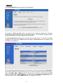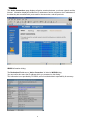
1
PCX5000
Wireless Cable Modem Gateway
Owner’s Manual
1
Warning:
This product may not be exported outside the US and Canada without US Department of Commerce,
Bureau of Export Administration authorization. Any export or re-export by the purchaser, directly or
indirectly, in contravention of U.S. Export Administration Regulation is prohibited.
Product and company names in this Owner’s manual are trademarks or trade names of their
respective companies.
Copyright 2002, Toshiba Corporation. All rights reserved. This manual may not be reproduced, in
part or in whole, without the permission of Toshiba Corporation. The content of this manual is subject
to change without notice in the future. Toshiba Corporation assumes no liability for damages
resulting from the use of this product or the information contained in this manual.
Table of Contents
Introduction ..................................................................................................................................4
Features.................................................................................................................................... 4
System Requirements ............................................................................................................... 4
Contact Information ................................................................................................................... 4
Important Rules for Safe Operation.............................................................................................5
Installation ................................................................................................................................. 5
Use and Maintenance................................................................................................................ 6
Service ...................................................................................................................................... 6
Overview .......................................................................................................................................7
How does the PCX5000 work? .................................................................................................. 7
How does the PCX5000 connect to a computer?....................................................................... 7
How does the PCX5000 differ from a stand-alone DOCSIS cable modem? ............................... 7
What is DOCSIS? ...................................................................................................................... 7
Getting Started.............................................................................................................................8
Contacting your Cable Provider. ................................................................................................ 8
Package Contents for the PCX5000 Wireless Cable Modem Gateway ...................................... 8
PCX5000 Front and Rear View.................................................................................................. 9
CD-ROM Contents .................................................................................................................. 10
Viewing the Owner's Manual ................................................................................................... 10
Setting Up Your PCX5000 and Computers ...............................................................................11
Installing the PCX5000 .............................................................................................................11
Mounting the PCX5000 on a Wall............................................................................................ 13
Configuring Your Computers.....................................................................................................14
Installing the Ethernet Connections ......................................................................................... 14
Installing the USB Drivers........................................................................................................ 15
Configuring the Computer for Wireless Operation.................................................................... 16
Windows Network Configuration.............................................................................................. 17
Network Configuration for Windows 98SE and Windows Me: ...............................................17
Network Configuration for Windows 2000:............................................................................18
Network Configuration for Windows XP: ...............................................................................19
Macintosh Ethernet and Wireless Network Configuration......................................................... 20
Macintosh OS 9 Configuration..............................................................................................20
Macintosh OS X Configuration..............................................................................................22
Configuring the PCX5000 Gateway...........................................................................................23
The PCX5000 Administration Pages........................................................................................ 25
PCX5000 Wireless Configuration ............................................................................................ 34
SofaWare Advanced Security Features ................................................................................... 37
Appendix.....................................................................................................................................43
Frequently Asked Questions.................................................................................................... 43
LED Diagnostics...................................................................................................................... 47
Specifications .......................................................................................................................... 48
Regulatory............................................................................................................................... 49
Glossary.................................................................................................................................. 50
STANDARD LIMITED WARRANTY......................................................................................... 52
End-User License Agreement.................................................................................................. 53
3
Introduction
Congratulations on your new purchase!
Your new Toshiba DOCSIS Wireless Cable Modem Gateway will provide you with high-speed
access to the Internet through your cable TV (CATV) network, allowing you to access your favorite
sites at a fraction of the time it takes traditional telephone modems. In addition, your service will be
always connected and Internet access may be shared with multiple computers. Those two features
give you the information you want, when you want it, and your telephone line is kept free.
The PCX5000 is one product that contains a Cable Modem, Router/Hub, Firewall and Wireless
Access Point. The integration of all these devices allows you to install a secure home computer
network at a minimal cost and effort.
Features
•
•
•
•
•
•
•
•
•
•
DOCSIS Certified Cable Modem
Ethernet Switch with four 10/100 BaseT interfaces
802.11b Wireless interface with:
• Built-in antenna
• 64 and 128 bit encryption
USB Interface for Microsoft Windows 98SE, 2000, Me and XP
Built-in Configurable Firewall and Router with:
• Network Address Translation (NAT)
• Stateful Packet Inspection
• DMZ Support
• Pin-hole Functionality for Networked Applications
DHCP Server for up to 25 Clients
Embedded HTTP Management and Administration Interface
Compatible with Microsoft Windows 98SE, 2000, Me and XP; MAC OS 9 and OS X
Free Technical Support
3 Year Limited Warranty
System Requirements
•
•
•
•
100-120V 50/60Hz AC Power Source
Microsoft Windows 98SE, 2000, Me and XP; MAC OS 9 or OS X based computer(s)
A CD ROM Drive in one computer with a 10/100 Ethernet or USB Interface
One of the following in each networked computer:
• 10/100 Ethernet Interface
• USB Interface (Windows OS only)
• 802.11b Wireless Interface
Contact Information
Support Information
Phone: (949) 583-3223
Fax:
(949) 583-3597
Web:
http://toshibacablemodems.buscom.net/form_techsetup.html
Sales Information
Phone: (949) 461-4840email:
[email protected]
Web Page
http://networks.toshiba.com
Important Rules for Safe Operation
In addition to the careful attention devoted to quality standards in the manufacture of
your Toshiba PCX5000, safety is a major factor in the design of every product.
However, safety is your responsibility, as well. This section lists important information
that will help assure your enjoyment and proper use of the PCX5000 and accessory
equipment. Please read it carefully before operating and using your modem.
Installation
Read and Follow Instructions - You should read all the safety and operating instructions before
operating the modem. Follow all operating instructions.
Retain Instructions - You should save all the safety and operating instructions for your future
reference.
Heed Warnings - Comply with all warnings on the PCX5000 and in the operating instructions.
Use the Recommended AC Adapter - You must use the adapter that comes with your Toshiba
PCX5000.
Check Power Sources – The AC adapter for your Toshiba PCX5000 must be used with a
AC100V-120V 50Hz/60Hz supply outlet. If you are not sure of the type of power supplied to your
home, consult your dealer or local power company.
Be Careful of Overloading - Do not overload wall outlets or extension cords, as this can result in a
risk of fire or electric shock. Overloaded AC outlets, extension cords, frayed power cords, damaged
or cracked wire insulation, and broken plugs are dangerous. Periodically examine the cord, and if its
appearance indicates damage or deteriorated insulation, have it replaced by your service technician.
Protect Power Cords - Route power supply cords so that they are not likely to be walked on or
pinched by items placed upon or against them. Pay particular attention to cords where they are
attached to plugs and convenience receptacles, and examine the point where the power cord
attaches to the PCX5000.
Check Ventilation - Slots and openings in the enclosure are provided for ventilation to ensure
reliable operation of the PCX5000 and to protect it from overheating. Do not block or cover these
openings. Never block these openings by placing the PCX5000 on a bed, sofa, rug, or other similar
surface. Never place the PCX5 000 near or over a radiator or heat register, or any other heat source
(including amplifiers). Do not place the PCX5000 in a built-in installation, such as a bookcase or
equipment rack, unless you provide proper ventilation.
Do Not Use Accessories - Do not use attachments, unless they are recommended by Toshiba, as
they may cause electrical or fire hazards.
Do Not Use Near Water - Do not use the PCX5000 near water - for example, near a bathtub, sink or
laundry tub, in a wet basement or near a swimming pool.
Do Not Place Near a High Temperature Source – Do not use the PCX5000 near a source of heat
such as a kitchen range, a fireplace or a radiator.
Use Caution in Mounting the PCX5000 - Do not place the PCX5000 on an unstable surface. The
PCX5000 may fall, causing serious injury to a child or adult, as well as serious damage to the
PCX5000.
Use Care when Mounting on the wall - When mounting the modem to the wall, take extra
precautions to assure the modem is mounted securely. If the modem is not mounted securely, and
the modem falls, it may cause serious injury to a child or adult, as well as serious damage to the
PCX5000.
Do Not Use Near Medical Equipment – Do not operate the modem near equipment that is
susceptible to electrical interference, or is used for medical purposes. Do not use the modem near a
pacemaker or a patient care area in the hospital.
Ground the Cable Systems – Be sure that the outside cable system is grounded to provide some
protection against voltage surges and built-up static charges.
Section 810 of the national Electric Code, ANSI/NFPA No. 70-1984 (Section 54 of the Canadian
Electrical Code, Part 1) provides information with respect to proper grounding of the cable systems.
Important Information!
•
•
•
Do not disconnect the RF cable from your PCX5000 while the power to your modem is on.
Wait at least 10 seconds between disconnecting and reconnecting the PCX5000 with the
AC power adapter.
Unplug the PCX5000 from the wall outlet carefully, as the AC adapter may be hot.
Use and Maintenance
Unplug Power Before Cleaning - Do not use liquid or aerosol cleaners. Use a damp cloth for
cleaning.
Keep Objects Out of Openings - Never push objects of any kind into the PCX5000 through
openings such as the ventilation holes, as they may touch high voltage circuits and "short-out" parts,
which could result in a fire or electric shock. Never spill liquid on the PCX5000.
Protect From Lightning – Unplug the PCX5000 during a lightning storm, or when leaving it
unattended and unused for a long period. Remove the power adapter from the wall outlet, and
disconnect the cable system. This will prevent damage to the PCX5000 due to lightning and power
line surges. Take care not to touch the metal portion of PCX5000 or cables in a lightning storm.
Service
Do Not Remove Covers - Do not attempt to service the PCX5000 yourself, as opening or removing
covers may expose you to dangerous voltage or other hazards. Refer all servicing to qualified
service personnel. Removing the cover will VOID your warranty.
Refer Servicing to Qualified Service Personnel under the Conditions Listed Below
• If the power supply cord or plug is damaged.
• If liquid has been spilled or objects have fallen into the PCX5000.
• If the PCX5000 has been exposed to rain or water.
• If the PCX5000 does not operate normally as per the operating instructions.
• If the PCX5000 has been dropped or the case has been damaged.
• When the PCX5000 exhibits a distinct change in operation, such as the inability to complete its
self-test.
Require Safety Check - Upon completion of any service or repairs to the PCX5000, ask the service
technician to perform the recommended safety checks to verify that the PCX5000 is in a safe
operating condition.
Security Precautions
The PCX5000 provides your home network with the highest level of security. However, no product
can provide you with absolute protection against a determined effort to break into your system. We
recommend using additional security precautions, such as encrypting files and folders to protect
highly valuable or sensitive information.
If you are using the wireless access capability of the PCX5000 and the wireless security options
(encryption and access control) are disabled, an unauthorized user can penetrate your computers
with a remote wireless device. See the section “PCX5000 Wireless Configuration” in this manual
to set the appropriate wireless security parameters.
Range of Wireless Communication
The range of the wireless signal may vary according to the actual radio conditions at the location
where the wireless LAN product is installed. The range of wireless devices may be affected by metal
surfaces and high-density materials such as concrete walls. Range is also impacted due to
“obstacles” in the signal path of the radio that may either absorb or reflect the radio signal.
Overview
The PCX5000 provides you with high-speed data communications over the television cable network
by following the widely accepted DOCSIS standard. This standard, as defined by CableLabs™,
offers a combination of high performance and interoperability among all major cable system
operators in North America.
How does the PCX5000 work?
Digital signals are represented by high and low electrical voltage levels. The speed of how fast these
levels can switch and still be transmitted is determined by the "bandwidth" of the transmission
system. The pair of wires used in a telephone connection has a greatly limited bandwidth because of
their electrical characteristics. When a device called a modem is connected between the computer
output and the phone line, it generates an electrical wave whose strength and phase change in step
with the highs and lows of the computer's digital output. It is because of the "smoothness" of the
resultant signal that a higher data rate can be transmitted.
A cable modem “modulates” and “demodulates” electrical signals in the same way that the telephone
modem does. However, since coaxial cable can transmit much higher frequencies, cable modems
are far more complex. None of the activity caused by the PCX5000 disturbs your regular cable TV
reception.
How does the PCX5000 connect to a computer?
The 10/100 Ethernet connection, USB connection and 802.11b wireless connection used in this
device are emerging as the most popular means of networking computers together and to the
Internet.
How does the PCX5000 differ from a stand-alone DOCSIS
cable modem?
The standalone cable modem is designed to connect one computer. The PCX5000 is designed to
connect multiple computers using 10/100 Ethernet, USB and 802.11b wireless interface. For
standalone cable modems, you typically need to purchase an additional networking device called a
router to connect more than one computer to the cable modem. With the PCX5000, all of your
computers can share your high-speed connection.
The PCX5000 also includes advance security features such as a Stateful Inspection firewall that can
protect your personal information and your equipment from malicious damage by hackers. The
PCX5000 Stateful Inspection firewall is intelligent enough to know what applications should be
allowed to access your network, and those that should be excluded.
What is DOCSIS?
Data Over Cable Service Interface Specifications. DOCSIS defines interface requirements for cable
modems involved in high-speed data distribution over a cable television network. On November 17,
1997, Cable Television Laboratories, Inc. (CableLabs) and its members established a formal path of
certification for cable modem equipment suppliers to obtain an interoperability seal for their products
based on the DOCSIS specification. This certification process provides cable modem equipment
suppliers with a fast, market-oriented method for attaining cable industry acknowledgment of
compliance with DOCSIS.
Getting Started
Contacting your Cable Provider.
Please keep in mind that you will need to notify your cable internet provider before using the new
Toshiba PCX5000, even if you have a cable modem that is currently functioning with your computer.
Package Contents for the PCX5000 Wireless Cable Modem
Gateway
Make sure that you have received the following items. Contact your dealer immediately if any item is
missing or damaged,
l
l
l
l
l
l
l
One Toshiba PCX5000 Wireless Cable Modem Gateway
One 10/100BaseT LAN Cable (6 feet)
One USB Cable (5 feet)
One AC Power Adapter
One CD-ROM containing:
One Quick Start Guide
One Warranty Statement
PCX5000 Front and Rear View
Indicators for 10/100Base-T interface
Indicator for Wireless LAN interface
Connector for an 802.11b external antenna
Note: The external antenna is optional.
Indicator for USB interface
Indicator for TEST function
Indicator for Cable interface
Power indicator
Front View (figure 1)
10/100Base-T interface connectors ports 1 through 4
DC IN
5V 2.4A
RESET Switch
Note: This switch is used to re-set the
PCX5000 parameters to factory
default values.
TV coax cable input connector
USB interface connector type ‘B’
Rear View (figure 2)
Power connector
CD-ROM Contents
The included CD-ROM contains:
• Owner's Manual (PDF)
• USB Drivers for Windows 98SE, 2000, Me and XP
• Acrobat(R)ReaderTM Software
This CD-ROM is readable by Windows and Macintosh computers.
Important Information!
DO NOT insert this CD-ROM into a music CD player, as that may cause damage to
your ears or the music CD player.
Viewing the Owner's Manual
This owner’s manual is in the PDF format. To view this manual, perform the following steps:
1. Insert the CD-ROM into your computer’s CD drive.
2. Open the file “PCX5000.pdf” in the folder “ \Manual”.
3. The Adobe Acrobat®Reader™ Software should launch automatically. The Acrobat Reader must
already be installed on your computer.
0
Setting Up Your PCX5000 and Computers
The steps for connecting your PCX5000 to your home computer network are as follows:
1. Install the PCX5000 in your cable TV and home computer network.
2. Configure your computers’ Ethernet, USB or wireless interfaces.
3. Configure your computers’ TCP/IP network settings.
4. Configure the PCX5000 for operating in your environment.
Installing the PCX5000
To avoid overheating problems, do not place any objects on top of the PCX5000. Do not block the
ventilation holes on the top of the unit. The top of the unit should be at least four inches from any
obstruction.
Connect the PCX5000 using the following steps, referring to figure 3.
1. Turn off the TV and computer.
2. Connect the cable TV coax cable to the input connector of a signal splitter.
3. Connect a coaxial cable from one of the output connectors of the splitter to the input connector of
the television set.
4. Connect a coaxial cable from the other output connector of the splitter to the cable TV coax input
connector (marked “RF”) on the PCX5000 rear panel.
5. Connect the 10/100 Ethernet and/or USB cable(s) from your computer(s) to the 10/100 Ethernet
and/or USB connector(s) on the PCX5000 rear panel.
You can use any combination of the following three ways to connect your computer(s) to the
PCX5000.
• Ethernet (up to four computers directly connected)
• USB (one computer)
• Wireless (up to 126 computers)
6. Connect the AC power adapter to the DC IN 5V 2.4A jack on the PCX5000 rear panel. Then plug
in the AC power adapter to the wall electrical outlet.
Cable TV
Coax
Splitter
PCX5000 Cable Modem
4
3
2
1
RESET
RF
USB
DC IN
5V 2.4A
Television
AC Adapter
10/100
Ethernet
Connection
USB
C onnection
802.11b
Wireless
Connection
PCX5000 to Computer Connection (figure 3)
1
Once the AC adapter is connected to the modem, the power indicator LED on the PCX5000
front panel will light. The PCX5000 will start operating once power is connected. No additional
operator intervention is required. The PCX5000 will perform its self-test, and then automatically
find the data channel and register itself on the cable provider’s system. The front panel
indicators (LEDs) show that the PCX5000 is operating properly when they are in the following
condition (refer to figure 4):
PCX5000 Front Panel (figure 4)
POWER
CABLE
TEST
USB
WLAN
100Mbps[1-4]
Link/Act[1-4]
– On
– On
– Off
– On or flashing when USB is connected, Off when USB is not connected.
– Flashing when 802.11b wireless data is transmitted/received, Off when
wireless is not active.
– (Left LED) On when 100BaseT Ethernet is connected, Off when 10BaseT
is connected or no connection.
– (Right LED) On or flashing when Ethernet is connected, Off when Ethernet
is not connected.
If the PCX5000 front panel LEDs are not operating as described by the notes above, you may
refer to the “Diagnostics LEDs” section in the appendix of this manual for more information.
If the PCX5000 appears to be operating correctly, you may now proceed to the next step.
7. If you are using the USB interface, install the USB driver following the instructions described in
the “Installing the USB Drivers” section of this manual before proceeding to the “Windows
Network Configuration” sections.
If you are connecting to the PCX5000 via the Ethernet connections, and already have the
Ethernet hardware configured on your computers, you may power up your computers and
proceed to the “Windows Network Configuration” or “Macintosh Ethernet and Wireless
Network Configuration” section.
If you plan to use a wireless connection, please refer to “PCX5000 Wireless Configuration”
sections of this manual before proceeding to the section, “Windows Network Configuration” or
“Macintosh Ethernet and Wireless Network Configuration” section..
8. Once you have completed these steps, you should be able to connect to the Internet at high
speed. If you are still having problems making your connection, please refer to the Q&A section
at the end of this owner’s manual.
2
Mounting the PCX5000 on a Wall
You may hang the PCX5000 on a wall with two mounting screws.
Pick a site on the wall while noting the following:
• Position the unit where it is easy to see the LEDs.
• Select a place where the AC power adapter may rest on a flat surface.
adapter to hang from the cord!
Do not allow the AC
Position the mounting screws as follows, referring to figure 5 below:
• Place the screws level with each other at a distance of 4-3/4 inches.
• Leave the head of screw rising 3/16’s of an inch out of the wall
• Mount the PCX5000 on the screws.
Note: Wall mounting hardware is not included with the PCX5000. Please select screws and anchors
suitable for the wall.
!!!CAUTION!!!
Take extra precautions to mount the PCX5000 securely. If the PCX5000 is
not mounted securely and falls, serious harm or damage may result.
PCX5000 Mounting Diagram (figure 5)
Place the AC power adapter on a flat surface like a table.
3
Configuring Your Computers
The following sections describe the typical steps needed to configure your computer network to
communicate with the PCX5000. These procedures apply to all of the interfaces (Ethernet, USB, and
wireless) which you will connect to the PCX5000.
Examples of the network configuration steps for Windows 98SE, Me, 2000 and XP are explained
with screen shots in the “Windows Network Configuration” section. Macintosh configurations for
OS 9 and OS X are explained in the “Macintosh Ethernet and Wireless Network Configuration”
section. These procedures instruct you on how to set up your computer to obtain an IP address
automatically.
Before proceeding to the network setting section for your Windows or Macintosh computer, please
verify you have correctly installed and configured the networking interfaces for Ethernet, USB or
wireless 802.11b. Macintosh users please note that the PCX5000 does not support a USB
connection for the Macintosh computer. Macintosh users must use an Ethernet or wireless
(AirPort) connection.
Installing the Ethernet Connections
The PCX5000 has four 10/100 Ethernet ports that can be used to connect directly to a total of four
computers. Each port can be shared with more than one computer by connecting an Ethernet hub or
switch in between the PCX5000 and multiple computers. Each computer must have an Ethernet port
or card to connect directly or indirectly to the PCX5000.
Note that the PCX5000 is a stand-alone device and requires no special Ethernet driver to be installed
on your computers.
Your computer may already be configured with a built-in Ethernet port, or you may need to use an
add-in card. In either case, verify your Ethernet port is working correctly and your computer is
correctly configured for the TCP/IP protocol. Follow the instructions in the “Windows Network
Configuration” section for your operating system. If you do not have an entry for an Ethernet
adapter or TCP/IP protocol in the “Network” panel window, refer to your computer or Ethernet card
adapter documentation. You may need to reinstall your Ethernet adapter card, drivers and TCP/IP
protocol.
Macintosh users should refer to the “Macintosh Ethernet and Wireless Network Configuration ”
section to configure their network settings.
Once you have completed the network settings for your computer, you should be able to access the
Internet at high speed with the Ethernet interface. If you are still having problems making a
connection, please refer to the Frequently Asked Questions section in the appendix at the end of this
owner’s manual.
4
Installing the USB Drivers
If you are using the USB (Universal Serial Bus) interface to connect the PCX5000 to your Windows
PC via the USB, you must install the "USB Driver" in your computer. The USB Driver for your
operating system is located in the CD-ROM shipped with the PCX5000.
Please note that these USB Drivers only support a computer running Microsoft Windows 98SE,
2000, Me and XP. These drivers are not supported on the following operating systems: Windows 98
First Edition; Windows 95 or any earlier version of Microsoft Windows or DOS OS; Macintosh;
Unix/Linux; and IBM OS/2.
Before installing and using these drivers, please be sure to read the "End-User License
Agreement" which is enclosed in appendix of this owner’s manual. You will be deemed to agree to
this agreement if you use these drivers.
Preparation
1. Confirm the PCX5000 is ready by verifying the status panel LEDs. (See "PCX5000 Front Panel figure 4")
2. Insert the USB Drivers CD-ROM into your CD-ROM drive.
3. Plug the “Type B” end of the USB cable into the back of the PCX5000.
4. Plug the “Type A” end of the USB cable into the USB port of your computer.
5. Turn on your computer.
Installing the USB Drivers
After following the instructions described in "Preparation" on this page, your Windows PC should
finish its boot process and display a window identifying the PCX5000 as a new device and
requesting its driver.
In general, follow these steps for installing the USB drivers.
1. Select “Search for the Best Driver” for your device" and click “Next”.
2. Select "CD-ROM drive" and click "Next".
3. Windows should then begin installation.
4. Click "Finish" to complete the installation.
The following is an example for Windows 2000. Windows 98SE, Me and XP operating systems
should operate in the same way.
Windows 2000 USB Driver Installation Example
Step 1: Shortly after restarting your computer,
you should see the following pop-up window:
Step 2: After a few seconds, the Found New
Hardware Wizard will prompt you through the
driver install process. Press the “Next” button.
The next set of windows will prompt you to
specify the location of the driver.
Select
“Search for a suitable driver for my device
(recommended)”, press “Next” and then select
“CD-ROM drives” for the driver location.
5
Step 3: Windows will search the CD-ROM
drive for the USB driver. When it has found
the driver, it will prompt you to go ahead with
the installation. Press the “Next” button again.
Step 4: The process will repeat for installing
the “Toshiba PCX5000 Cable Modem
networking support”. When the installation
is complete, you should see the following
window on the left:
Step 5: Press the “Finish” button. Your may
now proceed to the “Windows Networking
Configuration” section.
Important Information!
If you have trouble installing the USB drivers for your new PCX5000, you
may have inadvertently installed the USB Composite Device Driver that
Windows 98SE automatically loads. To correct this problem, please execute
the following instructions:
USB Composite Driver Removal
1. Make sure that the USB cable is plugged into your computer.
2. Restart your computer.
3. At the Windows desktop, click on the “Start” button; select "Settings" and then "Control Panel".
4. From inside the "Control Panel", choose "System".
5. Choose the tab on the top of the screen for "Device Manager".
6. Click the "+" next to "Universal Serial Bus Controllers".
7. Click "USB Composite Device " to select it and choose "Remove".
8. Once the USB Composite Device is removed, restart your computer and follow the instructions
starting with the “Preparation” section of this page.
Configuring the Computer for Wireless Operation
Please refer to the specific configuration instructions included with your wireless device for
installation instruction. Wireless device must be 802.11b(Wi-Fi) compliant to be used with the
PCX5000. These devices can be a PCI card, a PCMCIA card, or USB-based wireless access device.
The default settings for your wireless device to communicate with the PCX5000 are as
follows.
Wireless: Enabled or On
Wireless Network Name (also called the ESSID): PCX5000
Encryption: Disabled
Channel: 6
Mode: Infrastructure
Your wireless device may have more settings. Refer to your device documentation for the default
settings and configure up your wireless device appropriately.
Detailed instructions for the Macintosh AirPort wireless card are provided in the “Macintosh Ethernet
and Wireless Network Configuration” section of this manual.
16
Windows Network Configuration
Network Configuration for Windows 98SE and Windows Me:
The following is an example of how to configure a Windows 98SE and Me PC for TCP/IP network
settings:
Step 1: At the Windows Desktop, click “Start”,
then select “Settings”, and click “Control
Panel” as shown in the screen below. The
Control Panel window will appear.
Step 4: In the TCP/IP Properties panel,
choose the “Obtain an IP address
automatically” button and then press the
“OK” button.
Step 2: At the Control Panel window, select
and double click on the “Network” icon.
Step 5: Once you have completed the steps
above, a notice to restart your computer will
come up. Restart your computer.
Step 6: You should now be able to access the
PCX5000 configuration pages. Launch the
browser
and
open
location:”
http://192.168.100.1”
Proceed
to
the
“Configuring the PCX5000 Gateway”
section of this manual.
Step 3: In the Network panel window, scroll
down to the TCP/IP network adapter in your
computer. Select the “TCP/IP” line item and
click on the “Properties” button.
17
Network Configuration for Windows 2000:
The following is an example of how to configure the Windows 2000 TCP/IP network settings:
Step 1: At the Windows 2000 Desktop, click
“Start”, then select “Settings”, and click on
the “Control Panel” as shown in the screen
below.
Step 4: In the Local Area Connection
Properties panel, select the “Internet
Protocol (TCP/IP)”item and then click on the
“Properties” button.
Step 2: At the Control Panel window, select
and double click on the “Network and
Dial-up Connections” icon.
Step 5: In the Internet Protocol (TCP/IP)
Properties panel, select “Obtain an IP
address automatically”. Close each panel
by pressing the “OK” button.
Step 3: In the Network and Dial-up
Connections panel window, select and right
click on the “Local Area Connections” icon,
then select and click on the “Properties”
menu item.
Step 6: You should now be able to access the
PCX5000 configuration pages. Launch your
browser and open location:
http://192.168.100.1. Proceed now to the
“Configuring the PCX5000 Gateway”
section of this manual,
8
Network Configuration for Windows XP:
The following is an example of how to configure the Windows XP TCP/IP network settings:
Step 1: At the Windows XP Desktop, click
“Start”, then select and click on the
“Control Panel” item as shown in the
screen below.
Step 4: In the Network Connections window,
click on the “Local Area Connection” icon for
your Ethernet adapter. Then click on the
“Properties” button in the Local Area
Connection Status panel. In the Local Area
Connections Properties panel, select the
“Internet Protocol (TCP/IP)” item and then click
on the “Properties” button.
Step 2: At the Control Panel window, select
and double click on the “Network and
Internet Connections” icon.
Step 5: In the Internet Protocol (TCP/IP)
Properties panel, select “Obtain an IP address
automatically”. Click the “OK” button at the
bottom of the panel. Close each panel by
pressing the “OK” buttons.
Step 3: In the Network and Internet
Connections window, click on the “Network
Connections” icon located in the lower
right corner of the window.
Step 6: You should now be able to access the
PCX5000 configuration pages. Launch the
browser
and
open
location:”
http://192.168.100.1”
Proceed
to
the
“Configuring the PCX5000 Gateway” section
of this manual.
19
Macintosh Ethernet and Wireless Network Configuration
The following screens describe how to configure the network settings for a Macintosh
OS 9 computer.
Macintosh OS 9 Configuration
Ethernet Settings
Step 1: At the Macintosh desktop, click the
Apple icon at the top left of the screen,
select “Control Panel”, and then click on
the “TCP/IP” listing on the side panel.
Step 2: In the TCP/IP (Setup Ethernet)
panel, select the Ethernet port you are using
to connect your Macintosh to the PCX5000
in the Show choice box. The default port is
“Built–in Ethernet”. Then select “Using
DHCP Server” in the Configure choice box.
Close the panel by clicking on the top left
corner. You will be prompted to save the
configuration.
Step 3: You should now be able to access
the PCX5000 Configuration Pages.
Launch the browser supplied with the
Macintosh
and
open
location:”
http://192.168.100.1” Proceed to the
Configuring the PCX5000 section of this
manual.
0
Macintosh OS 9 AirPort Settings
If you are using the AirPort wireless connection, first verify the PCX5000 wireless link is turned on.
Refer to the “PCX5000 Wireless Configuration” page in this manual.
Step 1: Using the same procedure
described previously to set the Ethernet
TCP/IP configuration, navigate to the
TCP/IP (Setup Ethernet) panel and select
“AirPort” in the Connect via choice box.
Then select “Using DHCP Server” in the
Configure choice box.
You will be
prompted to save the changes.
The Setup Assistant will scan for nearby
802.11b wireless base stations. If the
PCX5000 is in range, it will respond with a
message announcing it has joined the
network.
If the AirPort Assistant cannot find a wireless
network, verify the Macintosh is in range of
the PCX5000 and that the PCX5000 has
had the wireless option turned on.
Step 3: If the AirPort Setup Assistant is
successful in finding the PCX5000 wireless
base station, it will display a panel stating,
“The AirPort Assistant is now ready to
configure your computer to access the
network “PCX5000”.”
Press the “Go
Ahead” button to proceed.
Step 2: At the Macintosh Desktop, double
click on the “Macintosh HD” icon, and
navigate to the “AirPort Setup Assistant”
icon
located
in
the
Applications/
Utilities/Assistants folder. Launch the
“AirPort Setup Assistant” application by
double clicking the icon. Select “Set up
your computer to join an existing AirPort
network”. Press the right arrow button to
continue.
Step 4: After several seconds, you will be
notified that the AirPort Assistant was
successful, and prompted to press the
“Connect Now” button. After pressing the
“Connect Now” button, your browser
should launch automatically.
Step 5: You should now be able to access
the Internet. You should immediately enable
wireless encryption. With a 10/100 Ethernet
connection,
open
location:
“http://192.168.100.1”. Proceed now to the
“PCX5000
Wireless
Configuration”
section of this manual to set the wireless
security options.
1
Macintosh OS X Configuration
Ethernet Settings
The following screen shots give an example of how to configure the network settings for a Macintosh
OS X computer.
Step 1: At the Macintosh desktop, select the
Apple icon at the top left of the screen, click
on “System Preferences”, then select and
click on the “Network” icon at the top of the
panel.
Step 2: In the Network panel, Select “Active
Network Ports” in the Show choice box to
verify your networking interfaces (Built-in
Ethernet, Add-on Ethernet, or AirPort)
are active.
Step 3: Then select the Ethernet port you
are using to connect your Macintosh to the
PCX5000 in the Show choice box. The
default port is “Built–in Ethernet”. Click on
the TCP/IP tab and select “Using DHCP” in
the Configure choice box.
Step 4: Click the “Apply Now” button at the
bottom right corner of the menu.
Step 5: You should now be able to access
the PCX5000 configuration pages. Launch
the browser supplied with the Macintosh and
open
location:
”http://192.168.100.1”
Proceed now to the “Configuring the
PCX5000 Gateway” section of this manual.
2
Macintosh OS X AirPort Settings
If you are using the AirPort wireless connection, first verify the PCX5000 wireless link is turned on.
Refer to the “PCX5000 Wireless Configuration” page in this manual.
Step 1: In the Macintosh OS X toolbar (located
at the top of the desktop) select the AirPort
broadcast icon and choose “Turn AirPort
On”.
Step 2: At the Macintosh desktop, double click
on the “Macintosh HD” icon, and navigate to
the “AirPort Setup Assistant” icon located in
the “Applications/Utilities” folder. Launch the
“AirPort Setup Assistant” application by
double clicking the icon. Select “Set up your
computer to join an existing AirPort
network”. Press the “Continue” button.
panel. Then select “AirPort” in the Show
choice box. Select the TCP/IP tab and select
“Using DHCP” in the Configure choice box.
Step 4: While in the Network Panel, select the
“AirPort” tab. Verify the Wireless Network
Name of the PCX5000 (default is “PCX5000”)
in the “Preferred Network:” text entry box.
The PCX5000 should be listed as one of the
available networks recognized by the AirPort
card.
The Setup Assistant will scan for nearby
802.11b wireless base stations. If the
PCX5000 is in range, it will respond with a
message announcing it has joined the
network.
If the AirPort Assistant cannot find a wireless
network, verify the Macintosh is in range of the
PCX5000 and that the PCX5000 has had the
wireless option turned on (see PCX5000
Wireless Configuration).
Step 3: At the Macintosh desktop, select the
Apple icon at the top right of the screen, click
on “System Preferences”, and select and
click on the “Network” icon at the top of the
Configuring the
Step 5: You should now be able to access the
Internet. You should immediately enable
wireless encryption. With a 10/100 Ethernet
connection,
open
location:
“http://192.168.100.1”. Proceed now to the
“PCX5000 Wireless Configuration” section
of this manual to set the wireless security
options.
PCX5000 Gateway
3
The following sections describe how to configure the network and security settings for the PCX5000.
You should be able to access these settings once you have completed the Ethernet or USB
installation for your computer. In most cases, you will not need to change the default settings of the
PCX5000.
If you plan to use the wireless access capability of the PCX5000, please review the “PCX5000
Wireless Configuration” section to set your security parameters. The default settings do not
protect your home network from an attack by an unauthorized wireless user.
The PCX5000 contains an embedded Web server that allows you to change its configuration. The
PCX5000 configuration web pages may be accessed through any Internet browser such as
Microsoft Internet Explorer (5.0 or later recommended).
These web pages are password protected to prevent unauthorized changes.
The PCX5000 configuration options are available in these web page locations:
Configuration Option:
Turn the firewall On/Off (default: On)
Setup access rules
Setup DMZ (Demilitarized Zone)
Setup host name
Setup fixed IP addresses for modem, PC’s
Change modem’s DHCP server settings
Change modem’s password
Upgrade firewall security
Enable wireless encryption
PCX5000 Web page location:
see “Security->Firewall” Web page
“Security->Allow”
“Security->DMZ”
“System->Internet->Advanced Setup”
“System->Internet->Advanced Setup”
“System->My Network”
“System->Password”
“System->Upgrade”
“Wireless”
You may also check the PCX5000 status:
View firewall report
View Internet statistics
View modem Status
see “Security->Report”
“Security->Report”
“Status”
To access the PCX5000 Web page:
1. Launch Web browser(Internet Explorer 5.0 or later recommended) on a computer connected to
the PCX5000.
2. Go to address: http://192.168.100.1
The PCX5000 Welcome page will appear.
4
The PCX5000 Administration Pages
This section describes how to access the PCX5000 settings through the browser interface.
Login for the first time:
If you are accessing the PCX5000 for the first time, or have reset the modem to its factory defaults,
you will be prompted for a login password. Enter the password of your choice into the dialog box.
Retain this password for future reference. You will need to enter this password to access the
PCX5000 internal settings.
Note: Write down the password in a secure place, as you will need it again to make changes to the
PCX5000 configuration. If you forget your password, you may reset your PCX5000 to factory
defaults using the Reset button (see figure 2). The Reset button is located behind the PCX5000 and
should be pressed for at least 10 seconds until the modem reboots.
If you have accessed the PCX5000 configuration page before, the screen above appears:
Enter your password and click “OK”.
Note: You will be automatically logged off after 10 minutes if no user input is received. You will need
to re-enter your password in order to access the PCX5000 administration pages.
5
PCX5000 Welcome Page
Once the correct password has been entered, you may access each of the PCX5000 administration
pages.
The Main Menu Side Bar, located on the left side of the web page, is used to navigate to a particular
configuration section.
Main Menu Side Bar Detail
Welcome
– The initial start-up screen
Security
– Firewall configuration pages
System
– Router and password configuration and status
Wireless
– Wireless access point configuration
Status
– PCX5000 status information
Help
– Simple references
Logout
– Exit the PCX5000 administration site
26
The Security pages are used for configuring the firewall.
The Firewall page displays the state of the firewall. The default setting for the firewall is “On”.
This setting is recommended for connecting to the Internet for most typical home installations.
When the firewall is turned “On”:
• The Stateful Inspection firewall engine will be enabled.
• The PCX5000 will operate in “router” mode, which will enable the internal DHCP Server. Please
refer to “System Configuration/My Network” web page description to change the network
addresses.
• The PCX5000 will enable NAT (network address translation - see Glossary). The PCX5000
automatically obtains a single IP address from the CSP (Cable Service Provider) and shares this IP
address with all of the computers on the home network.
If the firewall is turned “Off”:
• The Stateful Inspection firewall engine will be disabled.
• The PCX5000 will operate in “bridge” mode, which will disable the internal DHCP Server and
NAT (network address translation).
It is not recommended to turn the firewall off unless you already have a firewall appliance or router
that is installed in between the PCX5000 and your computers.
Important Information!
Turning Off the firewall will leave your computer vulnerable to an attack.
Important Information!
When you turn on/off the firewall, you need to power off and on PCX5000 and
reboot your PC after PCX5000 starts.
7
The Security/Allow page is used to allow network applications such as a peer-to-peer music file
sharing program to work with your firewall.
PCX5000 utilizes a Stateful Inspection Firewall that in most cases will recognize those applications
that need access through the firewall, and will automatically configure the modem appropriately. If
you experience problems with network access in using an application, refer to the application
documentation for “port numbers” and “protocols” that are used by that application. Enter the port
and protocol information, as well as the IP address of the computer running the application.
The Security/DMZ page is used to allow unlimited access from the Internet to a computer in your
home network. The default setting for this page is all computers are protected.
The DMZ IP Address is used to identify a single computer on your network that will reside outside of
the firewall and allow for unlimited access to and from the Internet.
Important information!
If you enter the IP Address of a computer, the Firewall will not protect this
computer.
8
The Security/Reports page provides the Firewall statistics.
By clicking the “Show me more ” button, you will get more information regarding the enhanced
firewall functionality available through the SofaWare upgrade. The SofaWare upgrade provides
more detailed reports on intrusion statistics for your firewall.
The Systems/Internet page shows the current Internet connection status. If you have successfully
connected to the Internet, the Status field should display “Connected” and the IP address of the
PCX5000 will be displayed.
If you are having trouble making an Internet connection, you may need to specify a “Host Name ”.
Some CSP’s (Cable Service Providers) require you to enter a host name to access their network.
With a Windows PC, you may identify the host name of your computer by right clicking the “Start”
button in the tool bar, selecting “Explore” and clicking on the “Network Neighborhood” icon
(Windows 98SE or Me) or “My Network Places” icon (Windows 2000, XP).
9
If a host name is required, click the “Advanced Setup” button on the PCX5000 System/Internet
page. The following screen will appear that will allow you to enter the host name:
\
The Get configuration automatically (using DHCP) check box should be left checked. When
enabled, the PCX5000 will automatically configure its routing settings based on the information
provided by the Cable Service Provider.
Some CSP’s may require fixed IP addresses for your computer, gateway, and DNS Server(s). In this
case, your cable operator will provide you with these addresses and they may be entered on the
Advanced Setup page. To access this page, uncheck the “Get configuration automatically
(using DHCP)” box.
Note: You must enter the IP Address, Subnet Mask, Default Gateway, and Preferred DNS
Server when manually entering the router settings
IP Address – This is the fixed address of the PCX5000 for access to the Internet. Your CSP should
supply this address.
Subnet Mask –Your CSP should supply this number.
Default Gateway – The address of the router at your CSP that provides the gateway to the Internet.
Your CSP should supply this address.
0
Preferred DNS Server – This is the address of the Domain Name System (DNS) server. The DNS
server translates an address name like “yahoo.com” into a numerical address. Your CSP should
supply this address.
Alternate DNS Server – This is the address of an alternate DNS server, if available. This optional
setting is supplied by your CSP.
After entering this information, make sure to click the “Apply” button to activate the changes.
The Systems/My Network page is used to assign the IP addresses for your LAN if you are using the
DHCP function in the PCX5000. The default setting for the DHCP server is “Enabled”.
The DHCP server works only when the Firewall/NAT is turned “On” as described in the
Security/Firewall web page. If you already have a DHCP server on your LAN, set the DHCP server
setting to “Disabled”
If you are using a different address with your DHCP server, enter that internal network address in the
My Network fields.
Note: If you change Internal Network address to ‘xxx.yyy.zzz.*’, the Gateway IP address will always
be ‘xxx.yyy.zzz.254’.
Regardless of the Internal Network Address setting, the IP address of PCX5000 configuration Web
pages will remain “192.168.100.1”.
1
The System/Password page is used to change the login password for accessing the PCX5000
configuration Web pages.
System/Upgrade page is used to upgrade the PCX5000 security features.
Additional security features are
available through the SofaWare
upgrade option. Clicking this
button will display current
upgrade options.
To upgrade your PCX5000,
1. Select the "Upgrade by
entering a new product key".
2. Click "Next".
2
3. Then the new screen appears.
4. Enter your product key that
you bought beforehand at the
SofaWare Web site.
5. Click "Next".
6. Then the new screen appears.
7. Click "Finish".
8. The new screen appears.
For more information upgrade
options, please access the
following Web site:
http://www.sofaware.com/pc
x5000/upgrade
3
PCX5000 Wireless Configuration
The PCX5000 includes an embedded 802.11b wireless access point to provide wireless connectivity
to the Internet. The Wireless Settings page is used to set the parameters needed for a wireless
network.
Wireless Enabled check box - When checked, the wireless 802.11b network is on.
unchecked, the wireless 802.11b network is off.
When
Wireless Net Name entry box - Also called the ESSID, the Wireless Net Name is the unique name
shared by all devices on the wireless network. All wireless devices on the network MUST use the
same Wireless Net Name to communicate with each other and the access point. The name can be
up to 32 characters long. By default, the PCX5000 uses “PCX5000” as the Wireless Net Name.
Exclude Other Nets check box - When checked, the PCX5000 will only recognize wireless devices
whose network name exactly matches the one entered into the Wireless Net Name entry box.
Wireless devices whose network name does not match will not be allowed to connect to the network.
When unchecked, the PCX5000 allows wireless devices whose network name matches and
wireless devices whose network name is ‘ANY’ to connect. All other network names will be rejected.
Wireless Channel selection box - Selects the wireless channel to use. Valid selections are 1 to 11.
The default is 6.
Note: You may change the Wireless Channel number when other wireless devices or access
points exist in adjacent area.
Enable Wireless Encryption check box - When unchecked, wireless encryption is disabled. When
checked, the PCX5000 will utilize encryption to secure the wireless connection. Enabling wireless
encryption will expand the Wireless Settings configuration page.
Important Information!
Leaving the “Enable Wireless Encryption” check box unchecked may allow
an unauthorized user to gain access to your home network. It is strongly
recommended to enable wireless encryption if you are using a wireless
access device.
34
When wireless encryption is enabled, the Wireless Settings page expands to include encryption
options.
Exclude Unencrypted check box: When checked, only wireless devices with matching encryption
keys will be allowed to connect to the PCX5000. When unchecked, wireless devices with matching
encryption keys and wireless devices with no encryption will be allowed to connect. It is strongly
recommended for security reasons to check this box.
Key Entry Type selection box: Selects the type of encryption to use (64-bit or 128-bit). 128-bit
encryptions offers stronger security, but may slow down your connection.
Key Entry Mode selection box: Encryption keys may be entered as alphanumeric characters
(select Key Entry Mode “Alpha”) or Hexadecimal numbers (use entry mode “Hex”).
Encryption Key entry box: The PCX5000 can decrypt up to four separate encryption keys. Enter
up to four encryption keys in these entry boxes. Typically, only one key is used. This key may be
entered into any entry box.
Transmit Using Key selection box: Select the encryption key to use when transmitting.
Important Information!
When you are using the encryption options, you will not make a wireless
connection if the encryption keys for the computer’s wireless access card and
the PCX5000 do not exactly match.
Important Information!
When an Encryption Key of PC corresponds with one of 4 Encryption Keys of
PCX5000, PC can access PCX5000.
5
The Status page summarizes basic information useful for installation and diagnostics.
PCX5000 Information
RF MAC Address
USB MAC Address
LAN MAC Address
802.11b MAC Address
Serial Number
Operational Status
Uptime
Last Status - prior reboot
Power Level Received
Power Level Transmitted
Received SNR
Frequency Downstream
Frequency Upstream
–
–
–
–
–
–
–
–
–
–
–
–
–
–
Hardware and software version information
MAC address of the RF interface
MAC address for the USB interface
MAC address used for router functions
MAC address of the 802.11b wireless interface
The serial number of the unit
The current status of the PCX5000
The time since the last PCX5000 reset
The status of the PCX5000 prior to the last reboot
The power of the downstream signal in dBmV
The power of the upstream signal in dBmV
The signal-to-noise ratio of the downstream signal in dB
The frequency of the downstream signal
The frequency of the upstream signal
6
SofaWare Advanced Security Features
This section explains the extended security capabilities available through the SofaWare upgrade.
You may purchase this upgrade by clicking on the link in the PCX5000 Welcome page or visiting the
site: http://www.SofaWare.com/pcx5000/upgrade.
After entering the upgrade key set, you should see this Welcome page. Note the “Safe@Home ” title
in the banner indicating you are running the upgraded security software.
Advanced capabilities provided by the SofaWare security upgrade include:
• Enhanced security reporting and diagnostics for your home network
• High, medium and low settings for firewall security
• Simplified specification of ports and protocols needed by applications such as mail, ftp and http
servers that you may host at home
Reports Pages
The reports pages are a set of screens that display a history of events concerning your home
network (Event Log), a list of computers active on the home network (Active Computers), and
current connections between the computers and the Internet (Active Connections).
The Event Log lists activities monitored by the PCX5000, including startup, connections made by
your computers, blocked connections, and attempts made by external users who may be trying to
break into your network.
7
The Active Computers page lists all computers on your home network that have been recognized
by the PCX5000 and are allowed to access the internet.
Pressing the “Licenses” button will list the
number of licensed users authorized with
the SofaWare Safe@Home upgrade.
8
The Active Connections page displays all active sessions between your home network and the
Internet. Information displayed includes the IP addresses of active computers, the IP addresses of
the sites they are connected with, ports used for the connection, and the protocols.
WHOIS information dialog:
The Destination IP address on 'Active Connection' is linked to WHOIS dialog.
You can confirm who owns the IP address which you accessed on this dialog.
This information is not provided by PCX5000, and is furnished without responsibility for accuracy.
9
The enhanced Security pages enable additional flexibility in configuring the firewall. The first page
displayed, Fire wall, provides for three levels of security (Low, Medium and High). The default setting
is “Medium” security.
Low
Medium
High
All outbound traffic is allowed
All inbound traffic is blocked except for ICMP echo’s (“ping”)
All outbound traffic is allowed except for Windows file sharing (NBT ports
137, 138, 139 and 445).
All inbound traffic is blocked.
Restrictions apply to outbound traffic, allowing only Web traffic (HTTP,
HTTPS), Email (IMAP, POP3, SMTP), FTP, NNTP, Telnet, DNS, IKE, 2746
UDP and 256 TCP traffic out. All inbound traffic is blocked.
Important Information!
When you turn on/off the firewall, you need to power off and on PCX5000 and
reboot your PC after PCX5000 starts.
0
The Virtual Servers page allows you to specify computers on your home network to serve as web,
ftp, mail or other servers. You need not know the port numbers needed for each service.
The remaining configuration pages operate in the same manner as the standard version of the
PCX5000 software.
1
The Allow/Block Rules provide you with greater flexibility in defining and customizing your security
policy. You can allow additional inbound services which are not on the ‘Virtual Servers’ list, or block
outbound communications for specific port ranges.
If you wish to permit incoming access from the Internet to your internal network for specific port
ranges, you must create a new ‘Allow’ rule. If you wish to block outgoing access from your internal
network to the Internet for specific port ranges, you must create a new ‘Block’ rule.
2
Appendix
Frequently Asked Questions
Q: I have forgotten my password. What should I do?
A: Reset your PCX5000 to factory defaults using the Reset button. The Reset button is located
behind the PCX5000 and should be pressed until the device reboots (in about 10 seconds). Note
that all the configuration information you entered previously will have to be re-entered.
Q: Where can I download the driver for my PCX5000?
A: If you are only using the 10/100 Ethernet interface to connect your computers to the PCX5000,
there is no special driver needed on the computers.
If you are using the USB interface to connect a computer to the PCX5000, you must install the
PCX5000 USB Driver for Microsoft Windows 98SE, 2000, Me or XP. Drivers for each of these
operating systems are included in the CD-ROM packaged with this product.
You may download new versions of the USB drivers through the support web site:
http://www.toshiba.com/taisnpd/support/downloads.html
Q: Do I need to turn off the PCX5000?
A: No, you can leave PCX5000 powered up, however, you should power down the PCX5000 and
your computers during an electrical (lightning) storm.
Q: How do I share my Internet connection between several PCs?
A: Simply connect your computers to the PCX5000 and set “assign IP address automatically” in
each of the computer’s local network settings. The PCX5000 runs a “DHCP server” that will
automatically assign unique IP addresses to all your computers and allow them to connect to the
Internet at the same time.
Q: Can I change the internal IP address range of my PCX5000?
A: Yes, you may change the internal subnet range. When doing so, the gateway IP address will
change automatically to be the last address on your new subnet. For example, if you change your
subnet range to 10.0.10.x, the internal IP address of the gateway will automatically change to
10.0.10.254.
Please refer to the “Configuring the PCX5000 Gateway” section of the manual.
Note: The IP address of the PCX5000 web configuration page does not change. It is fixed at
192.168.100.1.
Q: How do I configure a PC with a static IP address?
A: To configure a PC with a static IP address, use the upper IP range (x.x.x.128-x.x.x.253) reserved
for that purpose. The PCX5000 will not dynamically assign any other PC with these IP addresses.
Remember to set the subnet mask (255.255.255.0), gateway IP (default is 192.168.100.254) and
DNS addresses as provided by your service provider.
3
Q: Can I dial into my home network using the PCX5000?
A: No, the PCX5000 does not have the capability to dial and connect via the telephone network.
Q: Can I dial into my company’s VPN using the PCX5000?
A: No, the PCX5000 does not have the capability to dial and connect via the telephone network.
However, once connected to the Internet via the CATV network, the PCX5000 does support VPN
pass through allowing the VPN software in your PC be used to direct connect your PC to your
company's VPN via the Internet.
Q: How do I use the PCX5000 with an existing router?
A: You may use the PCX5000 in bridge mode. The PCX5000 will operate solely as a cable modem
and route all traffic to an external router. See “What is bridge mode?”
Q: Does the PCX5000 support IPX or AppleTalk?
A: No, the PCX5000 only supports the TCP/IP protocol with Apple products.
Q: Can I use a non-Windows PC or PDA to connect with the PCX5000?
A: Yes, as long as that device supports the TCP/IP protocol.
Q: What is unique about the PCX5000 Internet security solution?
A: Most cable and DSL routers implement only Network Address Translation (NAT), rather than
full-fledged Stateful Inspection firewall protection. The PCX5000 uses SofaWare technology, based
on Check Point Software Technologies’ enterprise-strength firewall. Running this advanced firewall
enables the PCX5000 to:
• Enforce a strict security policy on all inbound and outbound Internet traffic, allowing into the
network all authorized traffic and only that.
• Support numerous common consumer applications and protocols.
• Protect from denial of service attacks.
• Log intrusion attempts.
Q: What is the security policy enforced by the PCX5000 firewall?
A: The default security policy of the PCX5000 firewall blocks all traffic initiated from the outside of
your home network, and allows all outgoing traffic initiated from your home computers except for
NetBIOS (Microsoft file and printer sharing protocol).
The advanced security version from SofaWare supports these preset security levels:
Low
All outbound traffic is allowed
All inbound traffic is blocked except for ICMP echo’s (“ping”)
Medium
All outbound traffic is allowed except for Windows file sharing (NBT ports
137, 138, 139 and 445).
All inbound traffic is blocked.
High
Restrictions apply to outbound traffic, allowing only Web traffic (HTTP,
HTTPS), Email (IMAP, POP3, SMTP), FTP, NNTP, Telnet, DNS, IKE, 2746
UDP and 256 TCP traffic out. All inbound traffic is blocked.
Note: The default policy of the standard product is “Medium”.
4
Q: What do I need to do in order to host a web or mail server behind the PCX5000?
A: To enable remote access to a web server behind the cable modem, you will need to open the
firewall for incoming web traffic with these instructions.
1.
2.
3.
4.
5.
6.
7.
Open the PCX5000 configuration page at http://192.168.100.1/
In the left hand menu, click on “Security”.
In the top menu, click on “Allow”.
In the “Ports” text box, type ”80”.
From the “Protocol” dropdown menu, choose ”TCP”.
In the “Home IP” text box, type the IP address for the computer you will use for your web server.
Repeat the process using port number “25”, “SMTP” for the protocol, and entering the IP
address for your mail server.
8. Click “Add” to apply the allow rules created.
Using the advanced security upgrade from SofaWare, the following procedure should be used:
1.
2.
3.
4.
5.
6.
Open the PCX5000 configuration page at http://192.168.100.1/
In the left hand menu, click on “Security”.
In the top menu, click on “Servers”.
Check the “Allow” checkbox for the Web Server application.
In the “Home IP” text box, type the IP address for the computer you will use for your web server.
Click “Add” to apply the allow rules created.
Internet users will need to connect to your web server through the external IP address of the cable
modem, assigned by your cable provider. You will need to register a domain name with your provider
to make it easy for external users to find your site – otherwise, they will need to use an IP address.
Q: How is the configuration and management performed for the PCX5000?
A: The PCX5000 is managed locally from its Web-based interface or centrally by the service
provider.
Q: What additional subscription services are available for my PCX5000?
A: Select cable service providers may offer add-on subscription security services options that
include:
• Enhanced Firewall security services such as proactive security policy updates that keep your
firewall up-to-date against the latest attacks.
• Parental control services that block access to objectionable Web sites.
• Email anti-virus services that scan email attachments before they are downloaded to your
mailbox.
Q: How do I upgrade my PCX5000?
A: To upgrade your PCX5000, you
http://www.sofaware.com/pcx5000/upgrade/
will
need
to
purchase
an
upgrade
from
After you have completed the purchase process and have a product key, proceed with the following
steps:
1. Open the PCX5000 configuration page at http://192.168.100.1/
2. In the left hand menu click on “System”
3. In the top menu click on “Upgrade”
4. Click on the “Upgrade” button
5. Choose the upgrade option “Upgrade by entering a new product key”
6. Enter your product key
After completing these steps, you should notice that the user interface includes the new features of
the upgrade such as multiple security policies and detailed reporting.
5
Q: How will I be notified of new firmware upgrades?
A: Your cable operator will automatically apply firmware updates.
Q: What is router mode?
A: Router mode allows all of your computers to share a single IP address. This single shared IP
address (WAN IP) is provided by your CSP. The PCX5000 will dynamically assign local addresses
to all of your computers and enable them to share your connection. In router mode, the PCX5000
implements a Stateful Inspection Firewall to protect all of your computers from unauthorized access
from the Internet. The PCX5000 is shipped with router mode enabled.
Q: What is bridge mode?
A: Bridge mode disables the sharing of single IP address. Each of your computers will need to obtain
a unique IP address from your CSP. Contact your CSP to find out how to obtain additional IP
addresses for multiple computers. In bridge mode, the PCX5000 disables the Stateful Inspection
Firewall thus allowing all data from your computers to flow freely to/from the Internet. The PCX5000
is shipped with bridge mode disabled.
Q: What should I do if the PCX5000 configuration pages are not displayed properly?
A: Follow these steps:
1. Make sure you are using browser versions IE 5.0 or Netscape 4.5 or later.
2. If you are using Internet Explorer, click on “Tools” menu, and then “Internet Options”. In the
”General” menu, under “Temporary Internet files”, click on the “Settings” button. In the Settings
menu, click on the “Automatically” option under “Check for new versions of stored pages”.
Q: What should I do if I cannot access the PCX5000 configuration pages?
A: Follow these steps:
1.
2.
3.
4.
5.
6.
7.
Make sure the PCX5000 modem is turned on.
Make sure your PCX5000 is properly connected to the networked computers.
If you have more than one PC connected, try accessing to the PCX5000 pages from a different
PC. If you succeed, check your original PC's connections and network settings.
Turn off the PCX5000 and turn it on again after 10 seconds.
Type the PCX5000 IP address in the browsers' “Open Location” address bar. The default IP
address is 192.168.100.1.
Check your browser settings for any Proxy server settings and disable them.
Check your operating system network settings. Make sure no static IP addresses are defined.
6
LED Diagnostics
The PCX5000 has 13 status LEDs. The purpose of each LED (left to right) is detailed in the following
table:
Function
Color
POWER
Green
CABLE
Green
TEST
Amber
USB
Green
WLAN
Green
10/100 Mbps [1-4]
Green
Link/Act [1-4]
Green
§
§
§
§
§
§
§
§
§
§
§
§
§
§
§
§
§
§
§
Definition
dark for power off
bright for power on
dark for no downstream RF carrier present or power off
flashing slowly (approximately every second) for downstream RF
carrier present and ranging in progress
flashing fast (approximately 0.1 seconds) for registration in
progress
on for the PCX5000 registered and ready to transfer data
dark for initial self-test of the PCX5000 OK or power off
flashing for initial self-test of the PCX5000 in progress or software
down loading of the PCX5000 in progress
on for self-test failure of the PCX5000
dark for no USB link has been detected
on for USB link and no activity
flashing for user data going through USB Interface
dark for no WLAN link has been detected
flashing for user data going through WLAN
dark for 10Base-T connection
on for 100Base-T connection
dark for no carrier to/from computer present or power off
on for carrier to/from computer present
flashing for user data going through Ethernet
7
Specifications
Model Name
Model Number
Compliant Standard
PCX5000
DAZ8850F
DOCSIS 1.0 (1.1Based)
Interface
10/100Base-T (10/100Mbps, full/half-duplex, auto-sensing)
4 port; USB Device (12Mbps, full speed mode) 1 port
IEEE 802.11b
F type female 75ohm
64/256QAM
30Mbps (64QAM) /43Mbps (256QAM)
88MHz to 860MHz (edge to edge)
6MHz
-15dBmV to +15dBmV
(Automatically Gain Controlled by CM)
QPSK / 16QAM
320, 640, 1280, 2560, 5120kpbs (QPSK)
640, 1280, 2560, 5120, 10240kps (16QAM)
5 to 42MHz (edge to edge)
0.2, 0.4, 0.8, 1.6, 3.2MHz
+8dBmV to +58dBmV (QPSK)
+8dBmV to +55dBmV (16QAM)
(Output signal level of CM is automatically controlled by CMTS
through power ranging function)
Step: 1dB
NAT-ON: 252
NAT-OFF: 31 (31 MAC address)
1 to 31 (set by MIB)
16
32
192.168.100.xx / 255.255.255.0 (factory default)
192.168.100.2 to 192.168.100.127 (factory default)
192.168.100.128 to 192.168.100.253 (factory default)
192.168.100.254 (factory default)
192.168.100.1
Receiver
Transmitter
Computer Interface
Wireless Interface
Cable Interface
Demodulation
Physical Speed
Frequency Range
Bandwidth
Input Signal Level
Modulation
Physical Speed
Frequency Range
Bandwidth
Output Signal Level
Max. Number of CPEs
Filtering
MAC Address
LLC
IP
DHCP
Subnet / Mask
Server
Lease Address Range
Reserved Addresses
Gateway Address
HTTP Web
LAN-Side Address
Server
Frequency
Frequency Cache
Search
Channel Plan
Safety
EMC
Power
AC-DC Adapter
Supply
Internal Power Supply
Consumption
OSS
Protocol
MIB
Environment Operating temperature
Operating humidity
Storage temperature
Orientation
Reset switch
LED
Dimensions (without A C-DC Adapter)
Weight
8
4 entries
Supports 3 North American Channel Plan (STD, IRC, HRC)
UL1950, UL1310 (AC-DC adapter)
FCC Part 15 class B
100-120V±10%, 50/60Hz
(Note: AC Adapter itself is 100-240V, but AC cord is 120V)
DC 5V 2.4A (change connector)
10 Watts (approximately)
SNMP/ICMP
MIB II / MCNS MIB / Toshiba MIB
32°F (0°C) to 104°F (40°C)
10% to 90%(Non condensing)
-4°F (-20°C) to 140°F (60°C)
Horizontal and wall mounting
Reset to factory default
POWER, CABLE, TEST, USB, WLAN, 10/100Mbps[1-4],
LINK/ACT[1-4]
8.5” x 8”.8 x 1.7” (WxDxH) unit: inch
2.1lbs. (approximately)
Regulatory
FCC Notice:
This equipment has been tested and found to comply with the limits for a Class B personal computer
and peripherals, pursuant to Part 15 of the FCC Rules. These limits are designed to provide
reasonable protection against harmful interference in a residential installation. This equipment
generates, uses and can radiate radio frequency energy and, if not installed and used in accordance
with the instructions, may cause harmful interference to radio communications. However, there is no
guarantee that interference will not occur in a particular installation. If this unit does cause harmful
interference to radio or television reception, which can be determined by turning the equipment off
and on, the user is encouraged to try to correct the interference by one or more of the following
measures:
• Reorient or relocate the receiving antenna.
• Increase the separation between the equipment and receiver.
• Connect the equipment into an outlet on a circuit different from that to which the receiver is
connected.
• Consult the dealer or experienced radio/TV technician for help.
9
Glossary
10/100BaseT(10/100 Ethernet)
Unshielded, twisted pair cable with an RJ-45 connector, used with Ethernet LAN. “10/100” indicates
dual speed (10 Mbps or 100 Mbps), “Base” refers to baseband technology, and “T” means twisted
pair cable.
Cable TV Coax
Cable that allows wide bandwidth transmission over long distances. Coaxial cable (coax) comprises
an inner conductor surrounded by insulation. An outer conductor wraps around the insulation, which,
in turn, is covered by an outer plastic covering.
DHCP
Any machine requires a unique IP address to connect to the internet using Internet Protocol.
Dynamic Host Configuration Protocol (DHCP) is a communications protocol that assigns Internet
Protocol (IP) addresses to computers on the network. DHCP uses the concept of a “lease” or amount
of time that a given IP address will be valid for a computer.
DMZ
A DMZ (demilitarized zone) allows one computer to be exposed to the Internet. An example of using
a DMZ would be exposing a public server, while preventing outside users from getting direct access
form this server back to the private network.
Domain Name System (DNS)
The Domain Name System (DNS) refers to the internet domain names, or easy-to-remember
“handles”, that are translated into IP addresses. An example of a Domain Name is
‘www.toshiba.com’.
Ethernet card
A plug-in circuit board installed in an expansion slot of a personal computer. The Ethernet card
(sometimes called a Network Interface Card, or NIC) takes parallel data from the computer, converts
it to serial data, puts it into a packet format, and sends it over the 10/100 LAN cable.
F connector
A type of coaxial connector, labeled RF on the rear of the Toshiba PCX5000 that connects the
modem to the cable system.
Firewall
A program or a set of related programs, located on a network gateway server protecting your private
network resources from users (and abusers) on the Internet. A firewall inspects each packet to
determine whether it complies with the security policy and blocks illegal traffic. Packets do not enter
the home network unless they comply with the security policy.
Gateway
A gateway is a network point that acts as an entrance to another network.
Headend
The equipment, in the central office of the service provider, where the cable signals originate.
Hybrid Fiber/ Coaxial (HFC) system
A system where the trunk of the cable plant is fiber technology. Somewhere near the subscriber’s
home, the fiber is connected to a coaxial cable, and the signal is converted so that it is compatible
with the fiber media. The coaxial cable then runs through the branches of the network and is finally
dropped into the home.
HUB
A device used to connect multiple computers to the PCX5000.
Internet
A collection of interconnected networks used for worldwide computer-based communications.
IP Address
A unique, 32-bit address assigned to every device in a network. An IP (Internet Protocol) address
has two parts: 1) a network address and 2) a host address. Each network is assigned an address by
a government agency, and each company administrator assigns an address to each host computer.
0
MAC Address
The MAC (Media Access Control) address is a computer’s unique hardware number. When
connected to the Internet from your computer, a mapping relates your IP address to your computer’s
physical (MAC) address on the LAN.
Modem registration
The process the Toshiba PCX5000 uses to make itself known to the headend equipment. Once
authorized by the router, the modem is assigned upstream and downstream channels for data
communication.
NAT
Network Address Translation (NAT) is the translation or mapping of an IP address to a different IP
address. NAT is used to map several internal IP addresses to a single IP address, thereby sharing a
single IP address assigned by the CSP among several computers. Stateful Inspection Network
Address Translation (NAT) implementation supports hundreds of pre-defined applications, and
protocols.
Network driver
A (software) file included with the Ethernet card. The file is loaded on the computer to allow the
computer to recognize the Ethernet card. See Ethernet Card.
RJ-45
Connector on the Toshiba PCX5000, labeled 10/100 that connects the modem to a computer or to a
HUB.
Subscriber
A computer user in the home who accesses a data service using the Toshiba PCX5000.
Subnet
A network subdivision. When subnetting is used, the IP (Internet Protocol) address is divided into a
subnet number and a host number. Hosts and gateways identify the bits used for the network and
subnet number using a subnet mask.
TCP/IP communication stack
Software in the subscriber computer that processes packets through the communication layers. The
subscriber configures the IP address for the computer and the router default gateway in the software.
The TCP/IP communication stack handles all the communications with the subscriber’s application.
URL
A URL (Uniform Resource Locator) is the address of a file (resource) accessible on the Internet. The
type of resource depends on the Internet application protocol. On the Web (which uses the Hypertext
Transfer Protocol), an example of a URL is ‘http://www.toshiba.com’.
USB
Universal Serial Bus, standardized for easy connections between the computer and the other
peripherals. USB connects more than computers and peripherals.
WEP
WEP is Wired Equivalent Privacy, based on the use of 64-bit or 128-bit keys and the popular RC4
encryption algorithm as described in the IEEE802.11 standard. Wireless devices without a valid
WEP key will be excluded from network traffic.
1
STANDARD LIMITED WARRANTY
TOSHIBA AMERICA INFORMATION SYSTEMS, INC.
NETWORK PRODUCTS DIVISION
FOR THE UNITED STATES AND CANADA
What are the terms and duration of this Limited Warranty?
Toshiba America Information Systems, Inc.(“TAIS”) warrants to the first end-user customer that this Toshiba DOCSIS PCX5000
(“Product”) will substantially comply with manufacturer’s published specifications under normal use for a period of three (3) years from
date of purchase when purchased new from TAIS or a TAIS authorized reseller in the United States of America or Canada. After three
(3) years, this Limited Warranty shall be void.
If this Product fails to perform as warranted during the warranty period, TAIS will at its option repair or replace the Product at no
expense to you, except as provided below. During the warranty period, TAIS will repair or replace defective Product or parts with new
or reconditioned Product or parts at its option. All repair or replacement of the Product must be performed by TAIS or a TAIS
Authorized Service Provider. Reconditioned Product or parts will be equal in performance to the original Product or parts. All original
Products or parts replaced by TAIS become property of TAIS. Any replaced or repaired Product or part is warranted under the same
terms as this Limited Warranty for a period of ninety (90) days after the date of repair or replacement, or for the remainder of the
initial warranty period, whichever is longer.
What is not covered by this Limited Warranty?
This Limited Warranty DOES NOT INCLUDE repair or replacement to correct any damage caused by improper installation or
maintenance, improper connection with any device, external electrical fault, accident, disaster, misuse, abuse, modification to the
Product not approved in writing by TAIS, service other than by TAIS or a TAIS Authorized Service Provider, or any other cause
outside normal usage parameters. TAIS shall not be responsible for damage to or loss of any programs or data, or the costs of
recovering such programs or data. This Limited Warranty is valid only in the United States and Canada. You are responsible for
payment, at current rates, for any repair or replacement not covered under this Limited Warranty.
How do I obtain warranty service?
In order to receive warranty service, you must contact TAIS at the number below within thirty (30) days after discovering that the
Product does not comply with its specifications.
Product proof of purchase may be required in order to validate warranty eligibility. If the Product requires service, you will be given a
return authorization number and instructions for shipping the Product to TAIS or the location of the nearest TAIS Authorized Service
Provider. You must pre-pay all transportation, taxes, duties and insurance charges incurred for shipment to TAIS or an Authorized
Service Provider, and properly pack the Product for shipment in the original packaging or equivalent. You will not be reimbursed for
these expenses. If the Product is not insured, and the Product is lost or damaged during transit, you are responsible for such loss or
damage.
Disclaimer and Limitation of Remedy
ALL OTHER EXPRESS OR IMPLIED WARRANTIES OR CONDITIONS, INCLUDING THE IMPLIED WARRANTIES OF
MERCHANTABILITY AND FITNESS FOR A PARTICULAR PURPOSE, ARE HEREBY DISCLAIMED. TAIS EXPRESSLY
DISCLAIMS ALL WARRANTIES NOT STATED ABOVE. ANY IMPLIED WARRANTIES THAT MAY BE IMPOSED BY LAW ARE
LIMITED IN DURATION TO THE TERM OF THIS LIMITED WARRANTY. SOME STATES OR PROVINCES DO NOT ALLOW
LIMITATIONS ON HOW LONG AN IMPLIED WARRANTY MAY LAST, SO THE ABOVE LIMITATIONS MAY NOT APPLY TO YOU.
IF THE PRODUCT DOES NOT PERFORM AS WARRANTED, THE SOLE AND EXCLUSIVE REMEDY SHALL BE REPAIR OR
REPLACEMENT. IN NO EVENT SHALL TAIS, TOSHIBA CORPORATION, OR ANY DEALER, DISTRIBUTOR OR AUTHORIZED
SERVICE PROVIDER BE LIABLE FOR ANY DAMAGES IN EXCESS OF THE PURCHASE PRICE OF THE PRODUCT. THIS
LIMITATION APPLIES TO DAMAGES OF ANY KIND, INCLUDING BUT NOT LIMITED TO DIRECT OR INDIRECT DAMAGES,
LOST PROFITS, LOST SAVINGS, LOST DATA, OR OTHER SPECIAL, INCIDENTAL, EXEMPLARY OR CONSEQUENTIAL
DAMAGES, WHETHER FOR BREA CH OF CONTRACT, TORT OR OTHERWISE, OR WHETHER ARISING OUT OF THE USE OF
OR INABILITY TO USE THE PRODUCT, EVEN IF TAIS, TOSHIBA CORPORATION, OR ANY DEALER, DISTRIBUTOR OR
AUTHORIZED SERVICE PROVIDER HAS BEEN ADVISED OF THE POSSIBILITY OF SUCH DAMAGES, OR OF ANY CLAIM BY
ANY OTHER PARTY. SOME STATES OR PROVINCES DO NOT ALLOW THE EXCLUSION OR LIMITATION OF INCIDENTAL OR
CONSEQUENTIAL DAMAGES, SO THE ABOVE LIMITATION OR EXCLUSION MAY NOT APPLY TO YOU.
THIS LIMITED WARRANTY GIVES YOU SPECIFIC RIGHTS, AND YOU MAY ALSO HAVE OTHER RIGHTS, WHICH VARY
FROM STATE TO STATE AND FROM PROVINCE TO PROVINCE.
TOSHIBA AMERICA INFORMATION SYSTEMS, INC.
Network Products Division
9740 Irvine Boulevard
Irvine, California 92618-1697
USA
Phone number: (949) 583-3223
2
End-User License Agreement
This End-User License Agreement (hereinafter this “Agreement”) is a legally-binding agreement between the customer,
either an individual or a single legal entity (hereinafter “the Customer”) and Toshiba Corporation (hereinafter “Toshiba”)
with respect to the following software (hereinafter “Software”):
(a)
USB Driver Software for Toshiba PCX5000, and
(b)
Any software incorporated in or attached to Toshiba PCX5000.
By installing, copying, or otherwise using the Software, the Customer shall be deemed to agree to the terms and
conditions of this Agreement. If the Customer does not agree to the terms and conditions of this Agreement, the
Customer shall be requested to return promptly the whole system of Toshiba PCX5000 including the Software unused to
the distributor or other from whom the Customer has received the system.
1.
Title to Software
The Customer acknowledges that Toshiba or its supplier(s) retains all title to the Software and all applicable intellectual property
rights in the Software, including without limitation, copyrights, patents, trade secrets and trademarks.
2.
Grant of License
This Agreement grants the Customer a non-exclusive license to:
(a)
Install the Software recorded on an external media into the Customer’s personal computer(s) and use the Software on and
with a single personal computer for the purpose of processing the internal data of the Customer for use of Toshiba PCX5000
(hereinafter “Purpose”), and
(b)
Make one (1) copy of the Software recorded on an external media for the purpose of backup.
3.
Restrictions
The Customer may:
(a)
Not disassemble, decompile or reverse engineer the Software,
(b)
Not make copies of the Software for any purpose other than backup,
(c)
Not install or use the Software for any purpose other than the Purpose or provide any third party or any employee of the
Customer with access to the Software for any purpose other than the Purpose,
(d)
Not modify the Software or create derivative works of the Software,
(e)
Not sell, offer to sell, distribute (including through multiple tiers) the copies of the Software or publish the Software, or
(f)
Not rent or lease the Software.
Not remove or erase any copyright notice or legend from the Software.
4.
Transfer
The Customer may permanently transfer all of the Customer’s rights under this Agreement to any third party, provided that the
Customer retain no copies and the recipient agrees to the terms and conditions of this Agreement.
5.
Export
The Customer agrees not to export, license or otherwise transfer the Sof tware to any country where such transfer is prohibited by
the United States Export Administration Act, or any successor legislation, or in violation of the laws and regulations of Japan or any
other country.
6. Termination
Without prejudice to any other rights, Toshiba may terminate this Agreement if the Customer fails to comply with the terms and
conditions of this Agreement. In such event, the Customer must immediately cease to use the Software and all copies thereof.
7.
United States Government Restricted Rights
If the Customer is an institution, department or other organization unit of the United States Government, the Software will be
classified as “Commercial Computer Software” and the United States Government will be acquiring only “Restricted Rights” in the
Software.
8.
Miscellaneous
The governing law of this Agreement shall be the laws of Japan. Disputes in connection with this Agreement shall be subject to the
exclusive original jurisdiction of Tokyo District Court of Japan.
9.
No Warranty
THE SOFTWARE IS PROVIDED “AS IS”. TO THE MAXIMUM EXTENT PERMITTED BY APPLICABLE LAW, TOSHIBA AND ITS
SUPPLIER(S) MAKE NO WARRANTY OF ANY KIND, EITHER EXPRESS, IMPLIED, OR STATUTORY REGARDING THE
SOFTWARE. TOSHIBA AND ITS SUPPLIER(S) EXPRESSLY DISCLAIM ANY IMPLIED WARRANTIES OF MERCHANTABILITY,
FITNESS FOR A PARTICULAR PURPOSE, NONINFRINGEMENT OF INTELLECTUAL PROPERTY RIGHTS, AND ANY OTHER
WARRANTY.
10.
Limitation of Liability
TO THE MAXIMUM EXTENT PERMITTED BY APPLICABLE LAW, IN NO EVENT SHALL TOSHIBA OR ITS SUPPLIER(S) BE
LIABLE FOR ANY DAMA GES WHATSOEVER, INCLUDING WITHOUT LIMITATION, DIRECT, INDIRECT, INCIDENTAL,
CONSEQUENTIAL OR SPECIAL DAMAGES, LOSS OF PROFITS, REVENUE, LOSS OF BUSINESS, LOSS OF DATA OR LOSS
OF USE, IRRESPECTIVE OF WHETHER TOSHIBA OR ITS SUPPLIER(S) HAS ADVANCE NOTICE OF THE POSSIBILITY OF
SUCH DAMAGES. THE CUSTOMER AND TOSHIBA AGREE THAT THESE LIMITATIONS ON POTENTIAL LIABILITIES WERE
AN ESSENTIAL ELEMENT IN SETTING CONDITIONS UNDER THIS AGREEMENT.
Toshiba:
Toshiba Corporation
Computer & Network Platform Division
1-1, Shibaura 1-chome, Minato-ku, Tokyo 105-8001, Japan
3