1
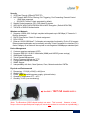
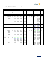
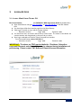
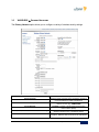
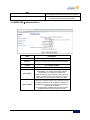
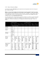
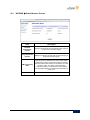
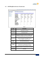
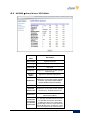
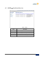
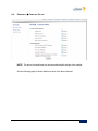
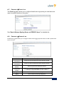
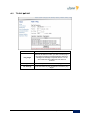
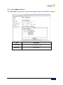
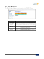
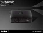
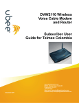
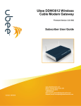
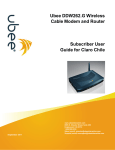
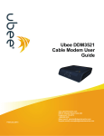
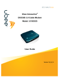
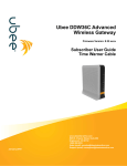
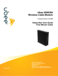
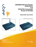
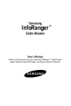
` Ubee DDW3611 Wireless Cable Modem/Advanced Wireless Gateway TWC Business Class Subscriber Wireless Configuration And Troubleshooting Guide Let’s make it easy Based on Firmware 8.6.2009 Ubee Interactive Americas Division th July 11 , 2011 Contents | Ubee Interactive 2011 1 NOTICES AND COPYRIGHTS Copyright © 2011 Ubee. All Rights Reserved. This document contains proprietary information of Ubee and is not to be disclosed or used except in accordance with applicable agreements. This material is protected by the copyright laws of the United States and other countries. It may not be reproduced, distributed, or altered in any fashion by any entity (either internal or external to Ubee), except in accordance with applicable agreements, contracts, or licensing, without the express written consent of Ubee and the business management owner of the material. Contents | Ubee Interactive 2011 2 REVISION HISTORY REVISION HISTORY Version Date Author Modification Comment 1.0 2011/07/11 Dan Hill 8.6.2009 release Contents | Ubee Interactive 2011 3 TABLE OF CONTENTS Revision History ...................................................................................................................................................................................... 3 Key Reference Documents ................................................................................................................................................................... 6 1 Device Overview ........................................................................................................................................................................... 8 1.1 Physical Specifications, Standards, Firmware Operations ................................................................................................. 8 1.2 2 DDW3611 LED Operational Summary ...................................................................................................................... 10 Login Access.................................................................................................................................................................................. 11 2.1: Login - Web UI and Telnet CLI ........................................................................................................................................... 11 2.2 Management Access Defaults ..................................................................................... Error! Bookmark not defined. 3. Wireless Configuration ................................................................................................................................................................... 12 3.1 Easy Wireless Configuration: ................................................................................................................................................. 12 3.2 Relevant Terms: ......................................................................................................................................................................... 12 3.3 WIRELESS Primary Network................................................................................................................................... 13 3.4 WIRELESS Wireless Radio ................................................................................................................................................ 14 4. Wireless Performance Improvements ........................................................................................................................................ 15 4.1: Wireless Performance Improvements ............................................................................................................................... 15 5 4.1.1 2.4GHz Channels and Frequencies ......................................................................................................................... 16 4.1.2 5GHz Channels and Frequencies............................................................................................................................. 17 4.1.3 Signal Attenuation – Receive Signal Strength Indicator (RSSI) ......................................................................... 18 4.1.4 Spatial Steams and Speeds ......................................................................................................................................... 20 FIREWALL Troubleshooting Tips ........................................................................................................................................... 21 5.1: Adding a DMZ Host ............................................................................................................................................................... 21 5.2: Can’t I PING the WAN Public IP of the Gateway ......................................................................................................... 21 6 CONNECTIVITY Troubleshooting Tips ..................................................................................................................................... 22 6.1 LEDs are OFF when cable modem is powered on. ................................................................................................. 22 6.2 LED for Ethernet port 1, 2, 3, or 4 on the cable modem is not lit. .................................................................... 22 6.3 General Connectivity Issues: ......................................................................................................................................... 22 6.4 My Ethernet device won’t connect to the network. ............................................................................................... 23 Appendix A – Key Web UI Troubleshooting Screens ................................................................................................................ 24 A.1 MODEM Cable Modem: Information .................................................................................................................... 24 A.2 MODEM Cable Modem: Status ............................................................................................................................... 25 A.3 MODEM Cable Modem: Downstream.................................................................................................................. 26 A.4 MODEM Cable Modem: Upstream........................................................................................................................ 27 Contents | Ubee Interactive 2011 4 A.5 MODEM Cable Modem Event Log ......................................................................................................................... 28 A.6 Firewall Content Filter .............................................................................................................................................. 29 A.7 Firewall Event Log ....................................................................................................................................................... 31 A.8 Firewall Remote Log .................................................................................................................................................. 31 A.9 TOOLS PING .............................................................................................................................................................. 32 A.10 Tools Trace Route ..................................................................................................................................................... 33 A.11 Tools Client List .......................................................................................................................................................... 34 Contents | Ubee Interactive 2011 5 KEY REFERENCE DOCUMENTS KEY REFERENCE DOCUMENTS The following documents are important references for detailed information, in addition to this Troubleshooting Guide: (1) Ubee_DDW3611_Subscriber_User_Guide (2) Ubee_DDW3611_Safety_User_Manual (3) Ubee_DDW3611_Data_Sheet Contents | Ubee Interactive 2011 6 INTRODUCTION Welcome to the Ubee family of data networking products. This DDW3611 TWC Business Class Subscriber Wireless Configuration and Troubleshooting Guide applies to the DDW3611 DOCSIS 3.0 Wireless Cable Modem is an Advanced Wireless Gateway with routing, firewall, parental control, VPN, and security capabilities. NOTE: This guide is designed to provide key information and recommendations in a format for quick consumption to help reduce installation times. Please refer to the DDW3611 Subscriber User Guide for detailed information. 1 DEVICE OVERVIEW 1.1 PHYSICAL SPECIFICATIONS , STANDARDS , FIRMWARE OPERATIONS The following are features and specifications of the DDW3611 Advanced Wireless Gateway. Interfaces Cable: F-Connector, Female LAN: 4 10/100/1000 Mbps RJ-45 Ports USB: 1 USB 2.0 HOST Port (USB port is powered, but is not activated for subscriber use. It is NOT a USB Client port, so it cannot be used for Internet access. Wireless: 802.11a/b/g/n, 2.4GHz or 5GHz (Simultaneous dual band not supported) Standards/Certifications DOCSIS 3.0/Euro DOCSIS 3.0 Certified DOCSIS/Euro DOCSIS 1.0/1.1/2.0 Certified Wi-Fi Alliance Compliant CE/ FCC Class B Downstream* Maximum Data Rate per Channel (up to 8 channels): DOCSIS = 30 Mbps (64 QAM), 42 Mbps (256 QAM), EuroDOCSIS = 41 Mbps (64 QAM), 55 Mbps (256 QAM) Total Max Bandwidth (8 Channels): DOCSIS = 343 (304) Mbps, EuroDOCSIS 444 (400) Mbps Symbol Rate: 6952 Ksps RF Input Power: -15 to +15dBmV (64 QAM), -15 to +15dBmV (256 QAM) Input Impedance: 75 Ω Upstream* Frequency Range: 5MHz ~ 65MHz Modulation A-TDMA: QPSK, 8, 16, 32, 64QAM, S-CMDA: QPSK, 8, 16, 32, 64, 128QAM Max B/W of 4 Channels = 122.88 (108) Mbps, B/W Per Channel (up to 4 channels) = [QPSK 0.32 ~ 10.24 Mbps, 8 QAM 0.48 ~ 15.36 Mbps, 16 QAM 0.64 ~ 20.48 Mbps, 32 QAM 0.80 ~ 25.60 Mbps, 64 QAM 0.96 ~ 30.72 Mbps, 128 QAM/TCM 30.72 Mbps] Symbol Rate: 160, 320, 640, 1280, 2560, 5120 Ksps RF Output Power: TDMA/ATDMA: +8dBmV to +54dBmV (32/64 QAM). ATDMA Only: +8dBmV to +55dBmV (8/16 QAM), +8dBmV to +58dBmV (QPSK). SCDMA: +8dBmV to +53dBmV (all modulations) *Actual speeds can vary based on factors including network configuration and speed. | Ubee Interactive 2011 8 Security VPN Pass-Through (IPSec/L2TP/PPTP) NAT Firewall, MAC/IP/Port Filtering, Port Triggering, Port Forwarding, Parental Control 1 DMZ Host supported 252 DHCP Private IP Hosts supported by default. Stateful Packet Inspection (SPI), DoS Attack Protection WPS/ WPA/ WPA2/ WPA-PSK& 64/128-bit WEP Encryption (Default WPA-PSK) TACACS or RADIUS Authentication Wireless and Network Supports 4 SSIDs, 802.11a/b/g/n compliant with speeds up to 300 Mbps (2 Transmit x 2 Receive Antennas) DHCP Client/Server / Static IP network assignment RIPv1/ RIPv2 Ethernet 10/100/1000 BaseT / full-duplex auto-negotiate functionality, IPv4 to IPv6 support. Ethernet speed and duplex can be manually set using Telnet Command Line Interface (CLI). 8-wire Category-5e or better will be required to auto-negotiate 1000Mbps per standard spec. Device Management Customer premises equipment (CPE) Supports IEEE 802.11e Wi-Fi Multimedia (WMM) and UAPSD (power savings) Web-Based Configuration Telnet Remote Management Secure Firmware Upgrade via TFTP Configuration Backup and Restore SNMP Support Interoperability with Arris, Casa Systems, Cisco, Motorola and other CMTSs. Physical and Environmental Dimensions: 172.2(W) x 254(D) x 42(H) mm Weight: 500 g Power: 12V/1.5A switching power supply (pictured below). Operating Temperature: 0°C ~ 40°C Humidity: 5~90% (non-condensing) Use ONLY 12V/1.5A POWER SUPPLY. (Note: The Broadcom 3380G chipset tends to run warm. This is normal. However, a lower Amp or other non-specified power supply will cause any modem to run hotter or unpredictably.) | Ubee Interactive 2011 9 1.2 DDW3611 LED OPERATIONAL SUMMARY LED Position LED Color LED1 LED2 LED3 LED4 LED5 LED6 LED7 LED8 LED9 LED10 LED11 Green Green/ Blue Eth-2 Green/ Blue Eth-1 Green Green Green/ Blue Green/ Blue Green USB Host Green/ Blue Eth-3 Green LED Label: Green/ Blue Eth-4 WPS Wi-Fi Online US DS Power CM Initialization CM Operation 1 Power ON On On On On On Off Off On On On On 2 Load Image Off Off Off Off Off On Flash Flash Flash On 4 DS Locked and Sync OK Off On, if connects On, if connects On, if connects Off Off On, if connects On, if connects On, if connects Off H/W Check On, if connects On, if connects On, if connects Off 3 On, if connects On, if connects On, if connects Off On Flash Flash On 5 US Ranging Off On, if connects On, if connects On, if connects On, if connects Off On Flash Flash 6 US Ranging OK Off On, if connects On, if connects On, if connects On, if connects Off On Flash 7 Registration OK Off On, if connects On, if connects On, if connects On, if connects Off On On 8 NACO Enable (network access) Off On, if connects On, if connects On, if connects On, if connects Off On On 9 NACO Disable Off On, if connects On, if connects On, if connects On, if connects Off On Off 1 Attached CPE On Green On Green, if connect, Blue if speed linked at 1000Mbp s (GigE) On Flash On Green, if connect, Blue if speed linked at 1000Mbp s (GigE) Flash, if connects On CPE Data Tx/Rx On Green, if connect, Blue if speed linked at 1000Mbp s (GigE) Flash, if connects On 2 On Green, if connect, Blue if speed linked at 1000Mbp s (GigE) Flash, if connects On, Green if 1 DS locked On, Blue if DS channel bonding On, Green if 1 DS locked On, Blue if DS channel bonding On, Green if 1 DS locked On, Blue if DS channel bonding On, Green if 1 DS locked On, Blue if DS channel bonding On, Green if 1 DS locked On, Blue if DS channel bonding On, Green if 1 DS locked On, Blue if DS channel bonding On, Green if 1 DS locked On, Blue if DS channel bonding On, Green if 1 DS locked On, Blue if DS channel bonding On, Green if 1 DS locked On, Blue if DS channel bonding On, Green if 1 DS locked On, Blue if DS channel bonding On, Green if 1 DS locked On, Blue if DS channel bonding On, Green if 1 DS locked On, Blue if DS channel bonding Flash Flash On On, Green if 1 DS locked On, Blue if DS channel bonding On, Green if 1 DS locked On, Blue if DS channel bonding On | Ubee Interactive 2011 10 On On On On On On 2 LOGIN ACCESS 2.1: LOGIN - W EB UI AND TELNET CLI Recommendation: (See DDW3611 MSO Operations Guide for detailed info.) Open Web Browser and type http://192.168.0.1 or http://192.168.100.1 in the URL Address field. You should get a Web User Interface page from the Ubee Gateway. Click Login on the left, and you will see a popup window. o Subscriber Account: Login: user Password: user You should now see a set of menu tabs at the top of the screen. The menus on the side bar are context sensitive, and change based on the menu tab you select. Same Login credentials are used for Telnet Command Line Interface. From Command Prompt, telnet 192.168.0.1 o Subscriber Account: Login: user Password: user IMPORTANT: The above are TWC required defaults. IP address, Subscriber Login and Password, and other settings may be changed during installation and provisioning. Please contact TWC Business Class for access information. | Ubee Interactive 2011 11 3. WIRELESS CONFIGURATION Configuring Wireless access for the DDW3611 Advanced Wireless Gateway (AWG) is quick and easy: 3.1 EASY W IRELESS CONFIGURATION : Time Warner Cable configures default values for all Wireless parameters. To start using your wireless network right away, follow these steps: Note the RF Cable MAC address on modem label (e.g,. C417FE7CD4BE). It will be used in multiple instances for configuration, connectivity and access. 3.2 RELEVANT TERMS: 1. Client Wireless Adapter (on PC, Mac, SmartPhone, etc) must support the speeds, frequencies, and security/encryption standards that are configured on the DDW3611 Advanced Wireless Gateway (AWG). 2. Primary Network (SSID) – This is normally broadcasted by the DDW3611 AWG for Wireless Clients to view and Connect. (e.g., DDW3611BE) 3. Encryption and Security – recommend using WPA-PSK with TKIP and WPA2PSK with AES. Newer adapters support WPA2-PSK with AES. WEP is old and not secure. 4. Pre-Shared Key (PSK) – sometimes called the Wireless Key or Wireless Password that is entered/stored on the DDW3611 and then compared when the Wireless Client tries to connect. (e.g., DDW36117CD4BE ) 5. 802.11 Wireless Frequency Band – recommend 2.4GHz, since most adapters, including 802.11b/g/n, will support 2.4GHz channels. a. Some newer 802.11n adapters will support 2.4GHz or 5GHz. b. Several channels are in each band. Choose a channel manually, or use AUTO Channel Selection to select for you. Clients reconnect to Primary Network SSID automatically upon channel change. 6. Wireless Client Connection – From your PC/Mac/SmartPhone/etc, View/Join/Connect to the DDW3611 Primary Network SSID that is being broadcast. Enter the Pre-Shared Key from Step 4 above. You will connect and then begin the DHCP IP request/offer process. Note: GATEWAY -> DHCP IP Pool – be sure you have sufficient IP addresses defined for allocation to wireless clients AFTER they connect successfully to the Primary Network SSID. | Ubee Interactive 2011 12 . 3.3 WIRELESS PRIMARY NETWORK The Primary Network option allows you to configure a variety of wireless security settings. Label Description Primary Network Wireless Primary Network status, Disabled by default for Commercial Business Class configurations. Wireless Primary Network Name (SSID) to which client devices connect. (E.g., DDW3611BE) Network Name (SSID) Closed Network WPA, WPA2, RADIUS, RADIUS Port, RADIUS Key WPA-PSK w/ TKIP, and WPA2-PSK w/AES Disabled by default to allow broadcast the Primary Network Name (SSID). Enable to allow for Centralized authentication for Wireless network access. Disabled by default. Enabled by default. Recommended security and encryption. WPA2 w/ AES are most secure and efficient. | Ubee Interactive 2011 13 WEP WEP encryption is disabled by default. Recommend leaving WEP disabled since it is not secure or efficient. WPS Enabled by default, but recommend disabling it due to inconsistent wireless client implementations. 3.4 WIRELESS WIRELESS RADIO Label Description Wireless Interfaces Displays the Wireless name / MAC address. Wireless Displays the wireless radio’s status, Enabled or Disabled. Country Select UNITED STATES Output Power 802.11 Band 802.11 n-Mode Always Select 100% You can choose 2.4Ghz or 5 Ghz, not both concurrently. ALL wireless client adapters MUST support 5GHz, if you decide to use 5GHz only. Note: The distance and coverage for 5Ghz is less than 2.4Ghz, but because there (currently) tend to be fewer 5GHz Wireless Access Points, this may be an option. Select Auto to use 802.11 n mode when possible. This mode has a significant increase in the maximum raw OSI physical layer data rate from 54 Mbit/s to a maximum of 600 Mbit/s with the use of four spatial streams when at a channel width of 40 MHz. One spatial stream at 20MHz wide channel will enable 72.2Mbps maximum data rate in 802.11n mode. | Ubee Interactive 2011 14 4. WIRELESS PERFORMANCE IMPROVEMENTS 4.1: WIRELESS PERFORMANCE IMPROVEMENTS Problem: Wireless link speeds and throughput are low. Recommendation: See Ubee_DDW3611_Subscriber_User_Guide.pdf for detailed configuration information. Change the Wireless Control Channel - Your wireless gateway operates in the 2.4GHz frequency range with 11 wireless channels available (USA). Ubee AWG default is Channel 1. Interference or congestion may result if this same channel is used by other Wireless Access Points (WAPs), 2.4GHz Phones, or other such devices. Try moving to another channel. o Login to the Gateway Web UI (see Section 2.1). o Click WIRELESS tab. o Click Radio on left-side menu. o Change the “Control Channel” to another channel, like 6 or 11 and click Apply. Run a speed test to check throughput. E.g., http://speedtest.net or Use TWC speed server in your area! Note: Non-overlapping channels include 1, 6 and 11 when channel width is 20MHz default. But you may find that another channel works better for your specific environment. NOTE: “Control Channel” set to “Auto” will enable automatic WiFi Control Channel change to the best channel; however, there are some caveats: 1. Control Channel test occurs every 15 minutes. 2. Control Channel will NOT change as long as a Wireless Client Station is connected to the Primary Network SSID. Click WIRELESS -> Access Control and scroll to bottom of page to be sure there are no wireless clients attached. Then check the auto selection capability. Be sure to run a speed test to verify. Move 2.4 GHz Phone - Try moving or relocating 2.4GHz cordless phones, which can operate in the same frequency range and can cause interference. (Auto-channel selection can help avoid problems.) Re-position the Wireless Gatway - Try positioning your Ubee Gateway at a higher point, and try to avoid obstructions that can reduce or reflect the wireless signal. o You can check the Receive Signal Strength easily using the RSSI indicator in the Ubee Gateway Web UI. 1. Login to the Web UI (see Section 2.1) (Do this wirelessly so you can move around.) 2. Click WIRELESS tab. 3. Click Access Control on left. 4. Scroll to the bottom to see Wireless Clients list. Find your wireless device and check the RSSI. Make sure it is between 0 and -67 for best performance and highest link speed. 5. Move your wireless device (SmartPhone, Laptop, etc) a few feet from the Wireless Gateway and refresh the Web UI page so that the AGE = 0. The RSSI should be in the 20s or -30s, and link speed should be optimal, based on your device’s wireless adapter. 6. Move away from the Wireless Gateway 20 feet or so, stop, refresh screen and note the RSSI value. As long as you are between 0 and -65, you should see optimal link speeds. Once you move into the -70 to -80 to -90 range, your link speeds as seen on your Wireless Client Application will be progressively lower until you lose connectivity. 7. Use this technique to find the optimum place to position your Wireless Gateway and your Wireless device. 8. Double pane, reflective windows, metal, metal duct work can reflect and absorb signals, When possible, try to position your PC in a line of sight to the Ubee Wireless Gateway to ensure the best signal level. | Ubee Interactive 2011 15 4.1.1 2.4GHZ CHANNELS AND FREQUENCIES 802.11b/g/n each support 2.4GHz channels and frequencies. The chart below illustrates “20MHz” wide channels. 802.11n supports “40MHz” wide channels, which would overlap even more and reduce the overall number of channels available for use. In the USA, channels 1 – 11 are used. Non-overlapping channels are 1, 6 and 11, as shown in the chart below. Auto-channel should be selected to ensure that the channel with least interference is used. If manual channel selection is desired, try selecting a channel with the least interference from other Wireless Access Points. Note: Via the Web UI, try selecting 40MHz channel width to see which channels are available. Source: IEEE (note: Only channels 1-11 are used in USA.) | Ubee Interactive 2011 16 4.1.2 5GHZ CHANNELS AND FREQUENCIES 802.11a/n each will support 5GHz channels. The table to the right shows the channel list and corresponding frequencies. Note: In the Web UI, try switching between 20MHz and 40MHz wide channels, and note which available channels disappear to make room for 40MHz channel width. (For example, channels such as 40, 48, 56, etc are not available.) Channel GHz 36 5.180 40 5.200 44 5.220 48 5.240 52 5.260 56 5.280 60 5.300 64 5.320 100 5.500 . 104 5.520 108 5.540 112 5.560 116 5.580 136 5.680 140 5.700 . 149 5.745 153 5.765 157 5.785 161 5.805 165 5.825 | Ubee Interactive 2011 17 4.1.3 SIGNAL ATTENUATION – RECEIVE SIGNAL STRENGTH INDICATOR (RSSI) Use the WIRELESS Access Control menu to view RSSI information for a client. From your wireless PC or MacBook, or iPad, Login to http://192.168.0.1 user/user and navigate to the Access Control menu. Refresh your screen show that the Age shows 0 indicating a current RSSI value. Move around the room and note how the RSSI value drops farther into the negative as you get farther from the Wireless Gateway, or as you go behind obstructions. Run some speed tests to note differences in performance. | Ubee Interactive 2011 18 Signal Attenuation and performance drops can result when the wireless signal is absorbed by an object or material, or as the wireless client moves farther away from the Wireless Gateway. The table below illustrates rule of thumb attenuation for different kinds of materials. Material Interior drywall Cubicle wall Wood door (hollow - solid) Brick / Concrete wall Glass / Window (not tinted) Double-pane coated glass Bullet-proof glass Steel/fire exit door Human Body Free Space Tree (est) Attenuation (dB) 2.4 GHz 5 GHz 3-4 2-5 3-4 6-18 2-3 13 10 13-19 3 .24/ft .15/ft 3-5 4-9 6-7 10-30 6-8 20 20 25-32 6 .5/ft .3/ft Sources: Furr, Oak Ridge National Labs, 2008, and IEEE | Ubee Interactive 2011 19 4.1.4 SPATIAL STEAMS AND SPEEDS The Table Below (source WiFi Alliance) shows spatial streams and expected link data rates for each type of 802.11 wireless technology. Note: If you view the Status window of your Wireless Client on your PC, upon initial connection to a wireless network, you will see receive capabilities, then you will settle on transmit capabilities (1 or more transmit spatial streams), appearing as link data rate from PC to wireless access point. Some 802.11n wireless adapters support 2 receive spatial streams, and only 1 transmit spatial stream, so max transmit data rate for 20MHz wide channel = 72.2Mbps link data rate with Short Guard Interval (SGI). So, in the example case with a Wireless adapter that supports 2 receives and 1 transmit, if you view the Windows Wireless Client application, you will first see 144.4Mbps (2 receive spatial streams), then 72.2Mbps (1 transmit spatial stream). See below the table below, last row 20Mbps channel width with SGI enabled, 1 stream vs 2 streams. Source: WiFi Alliance | Ubee Interactive 2011 20 5 FIREWALL TROUBLESHOOTING TIPS 5.1: ADDING A DMZ HOST Putting a host in the DMZ (De-Militarized Zone) outside the Firewall is a quick and easy way to enable remote access and functionality of devices such as Home Routers, Web Cameras, IP Phones and VOIP Telephone Adapters, Gaming Consoles, and other such devices without having to set up more complicated Port Forwarding or Port Triggering configurations. It is very easy to set up a DMZ Host. Solution: Login to the DDW3611 Web User Interface: http://192.168.0.1 Login: user Password: user TOOLS Client List, and note the MAC address and IP address that was assigned to the Web camera. GATEWAY Static Lease, and enter the Web camera’s WAN MAC address and assign a Static IP lease to it. Click Apply. GATEWAY DMZ, and enter the Static Lease IP address that you just assigned to the Web camera. Click Apply. 5.2: CAN’T I PING THE WAN PUBLIC IP OF THE GATEWAY Solution: From the Web UI: Login to Web UI (see 1.2.1). Click GATEWAY tab. Click Advanced Gateway Options on left. Uncheck “WAN IP Blocking”. From the Telnet/CLI: > wan-blocking disable > write | Ubee Interactive 2011 21 6 CONNECTIVITY TROUBLESHOOTING TIPS Use the following tips for resolving general issues with the device. 6.1 LEDS ARE OFF WHEN CABLE MODEM IS POWERED ON . Check the connection between the power adapter and the cable modem. Power off cable modem and wait for 5 seconds and power on the modem again. If the problem still exists, there may have a hardware problem. 6.2 LED FOR ETHERNET PORT 1, 2, 3, OR 4 ON THE CABLE MODEM IS NOT LIT. Try restarting the computer so that is could re-establish a connection with the cable modem. Check for a resource conflict (Windows users only). To do this: (1) Right-click on the My Computer icon on your desktop and choose Properties. (2) Click the Device Manager tab and look for a yellow exclamation point or red X over the NIC in the Network Adapters field. If you see either one, you may have an IRQ conflict. Refer to the manufacturers documentation or you cable service provider for further assistance. Verify that TCP/IP is the default protocol for your network interface card (NIC). Power cycle the cable modem by removing the power adapter from the electrical outlet and plugging it back in. Wait several minutes for the cable modem to re-establish communications with your cable service provider. 6.3 GENERAL CONNECTIVITY ISSUES : If your PC is connected to a hub or gateway, try connecting the PC directly into an Ethernet port on the cable modem. If you are using a cable splitter, try removing the splitter and connect the cable modem directly to the cable wall outlet. Wait several minutes for the cable modem to re-establish communications with the cable service provider. The Ethernet cable may be damaged. Try another cable. IMPORTANT: Some Ethernet cables may be labeled Category 5e, but only have 4 wires (2 pairs). These cables will only negotiate 100Mbps maximum. True Cat5e and Cat6 cables have 8 wires (4 pairs), which are required to support 1000Mbps (Gigabit Ethernet). 8-wire Cat5e Required for 1000Mbps 4-wire Ethernet 100Mbps max | Ubee Interactive 2011 22 6.4 MY ETHERNET DEVICE WON ’T CONNECT TO THE NETWORK. If the Ethernet device is a computer, it is possible that the computer does not have DHCP client enabled, which allows it to obtain an IP address automatically and join the network. See the steps below for Windows XP: a. Click “Start”, then right-click on “My Network Places” and select “Properties”. b. Right click on “Local Area Connection” and select “Properties”. c. Scroll down and click on “Internet Protocol (TCP/IP)” and select “Properties”. d. Click “Obtain an IP address automatically” and click “Obtain DNS server address automatically”, and click “OK”, then click “OK” to exit Local Area Connection Properties. Try 86400. eck number of CPE in the DHCP Pool to be sure it is not being exhausted. Check the IP address assignments under the GATEWAY -> DHCP section. TOOLS tab, Client List will also have IP client list. | Ubee Interactive 2011 23 APPENDIX A – KEY WEB UI TROUBLESHOOTING SCREENS A.1 MODEM CABLE MODEM : INFORMATION Label Description Cable Modem The current DOCSIS standard of the device. MAC Address The unique Media Access Control (MAC) hardware address of cable modem. This is the RF Cable MAC address. Serial Number The unique manufacturer serial number of the device. Boot Code Version The boot software code version of the device. Software Version The general software version of the device. Hardware Version The internal version number that identifies the hardware design. CA Key The device installs a Certificate Authority (CA) key that is transferred from the service provider’s server after the cable modem is authenticated. The key is used to secure communication between the service provider and the cable modem. | Ubee Interactive 2011 24 A.2 MODEM CABLE MODEM : STATUS Label Description Acquired Downstream Channel Displays a Downstream channel that the cable modem is trying to lock to and the progress. Ranged Upstream Channel Displays an upstream channel that the device is trying to range with and the progress. CM Provisioning State After the physical initialization, the cable modem will be configured by a DHCP server from the service provider. Once the cable modem obtains an IP address, the cable modem is online. The Status column shows the connection progress. The Comments column displays the messages indicating connection error information, if errors occur. Refresh Click to refresh the status information. | Ubee Interactive 2011 25 A.3 MODEM CABLE MODEM : DOWNSTREAM Label Description Frequency Displays the downstream channel frequency on which the cable modem is scanning. Lock Status Displays if the cable modem succeeded in locking to a downstream channel. Channel ID Displays the downstream channel ID. Modulation Displays the modulation method that’s required for the downstream channel to lock on to by the cable modem. This method is determined by the service provider. Symbol Rate Displays the symbol rate. The current cable modem downstream symbol rates are: QAM64 is 5056941 sym/sec, QAM256 is 5360537 sym/sec. Interleave Depth Displays the current cable modem downstream Interleave depth (4/8/16/32/64/128/other). Power Level Displays the receiver power level after ranging process. RxMER The Receiver Modulation Error Ratio is used to quantify the performance of a digital radio receiver in a communications system using digital modulation. Correctable Codewords Displays the quantity of codewords which are correctable. Uncorrectable Codewords Displays the quantity of codewords which are not correctable. | Ubee Interactive 2011 26 A.4 MODEM CABLE MODEM: UPSTREAM Label Description US-1 to US-4 Upstream Channels. Channel Type Displays the channel type. Channel ID Displays the current cable modem upstream channel ID. Frequency Displays the current cable modem upstream frequency (Hz). Ranging Status Displays the upstream ranging status. Modulation Displays the current cable modem upstream modulation type (QPSK/ QAM8 /QAM16/ QAM32/ QAM64/ QAM128/ QAM256). Symbol Rate Displays the symbol rate (Ksym/sec). Upstream Mini-Slot Size Displays the current cable modem upstream mini-slot size in Timebase Ticks of 6.25. Power Level T-1 Timeouts T-2 Timeouts T-3 Timeouts T-4 Timeouts Displays the current cable modem upstream transmit power (dBmV). T-1: Valid UCD not received, T-2: Ranging maintenance bcast not recvd, T-3: RNG-RSP time expired. US problem. T-4-RNG time expired. US or DS problem. (“Double-digit” T3 and T4 values could also indicate Bonding issue, provisioning or other such issue that results in continual reboot.) | Ubee Interactive 2011 27 A.5 MODEM CABLE MODEM EVENT LOG Label Description First Time Displays the time of the event. Last Time Displays the last time of the event. Priority Displays the event log severity. Description Displays a detailed description of the event log. Refresh Refreshes the event log record. | Ubee Interactive 2011 28 A.6 FIREWALL CONTENT FILTER NOTE: The above checked items are recommended default settings to be enabled. See the following page for further details on each of the above features. | Ubee Interactive 2011 29 Label Description Content Filter Settings Click the Enable button to enable a filter. Deselecting a checkbox disables the feature. Filter Proxy An enabled filter proxy server acts as an intermediary between a user and the Internet to provide security, administrative control, and caching service. When a proxy server is located on the WAN, it is possible for LAN users to circumvent content filtering by pointing to this proxy server. Filter Cookies Enable this filter to stop Cookies from being stored on a connected computer’s hard drive. Some web servers use them to track usage and provide service based on an ID found in the Cookies. Filter Java Applets Enable this filter to stop Java applets from being launched on connected computers. Java is a programming language and development environment for building downloadable Web components or Internet and intranet business applications. Filter ActiveX Enable this filter to stop ActiveX applications from being launched on connected computers. ActiveX is a tool for building dynamic and active web pages and distributed object applications. When you visit an ActiveX web site, ActiveX controls are downloaded to your browser, where they remain in case you visit the site again. Filter Popup Windows Firewall Settings Enable this filter to stop popup windows when visiting some websites Click the Enable button to enable a firewall setting. Deselecting a checkbox disables the feature. Block Fragmented IP Packets Enable this feature to have the firewall detect fragmented IP packets and block them. Important for some Gaming systems, Vonage TA or other VoIP Telephone Adapter, etc). Port Scan Detection Enable this feature to have the firewall detect port scan attacks. IP Flood Detection Enable this feature to have the firewall to detect IP flood attacks. Can result in slow web responsiveness due to high packet loss (as much as 90%) due to dropped packets as part of the protection algorithm. Firewall Protection Enable this feature to activate the firewall function. Disabling Firewall Protection does NOT disable all of the other feature settings in this table. You must enable/disable each one individually as appropriate. Protection against incoming connection requests on routed subnet Enable this feature to have the firewall to protect all of the routed subnets connected to the wireless router. | Ubee Interactive 2011 30 A.7 FIREWALL EVENT L OG The Event Log option allows you to configure firewall event log reporting via email alerts and report on possible attacks on the system. See “How to Setup a SysLog Server on DDW3611.docx” for detailed info. A.8 FIREWALL REMOTE LOG The Remote Log option allows you to configure firewall remote logging of specific events as traffic is passed and/or actions are taken. Label Description Permitted Connections Select to log all access attempts that are allowed by firewall. Blocked Connections Select to log all access attempts that are blocked by firewall. Known Internet Attacks Product Configuration Events Select to log all known attacks from Internet. Select to log whenever the DDW3611 Wireless Cable Modem Gateway is configured/modified by a user or admin. SysLog server Enter the IP address of the Syslog server. Apply Click to save the remote log configuration. | Ubee Interactive 2011 31 A.9 TOOLS PING Label Description Ping Target Enter the IP address to which you want to send a ping. A ping tests the network connectivity between devices by sending a test message to a specific device. You can also confirm the size of data sent is the same as received. Ping Size Enter the packet size to send for the ping operation. No. of Pings Enter the number of ping commands to send to the ping target. | Ubee Interactive 2011 32 A.10 TOOLS TRACE ROUTE The Trace Route utility traces the route that data is taking to and from the DDW3611 Gateway. Label Description Tracert Target Enter the specific IP address or domain (e.g. yahoo.com) to which you want to trace a route. MAX Hops Define the MAX hops. Hops is the number routers that the trace route traverses. | Ubee Interactive 2011 33 A.11 TOOLS CLIENT LIST The Client List option displays connected computers to the DDW3611 Gateway. Label Description Hostname/IP Address/MAC Address DHCP Clients currently connected to the DDW3611 Wireless Cable Modem Gateway are displayed in this list and are identified by the hostname, IP address, and MAC address of the connected devices. Interface The method that clients are connected to the device is displayed (for example, Ethernet LAN, Wireless). Refresh Click to refresh the client list. This may be useful when testing network connectivity between connecting clients and the DDW3611 Wireless Cable Modem Gateway. | Ubee Interactive 2011 34