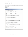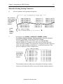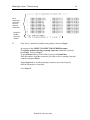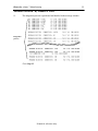
1
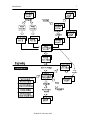
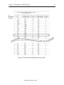
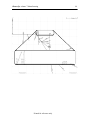
HarnesSYS
TM
User Manual
for
MANUFACTURING
HarnesSys volume 7 Manufacturing
2
Notices
The information contained in this manual is believed to
be accurate and reliable.
However, Israel Aerospace
Industries Ltd. (IAI) assumes no responsibility for any
errors, omissions, or inaccuracies whatsoever.
Information in this document is subject to change
without notice and does not represent a commitment on
the part of Israel Aerospace Industries Ltd. (IAI).
The software and/or data base described in this document
are furnished under a license and/or agreement. The
software and/or data base may be used or copied only in
accordance with the terms of such license and/or
agreement. It is against the law to copy the software on
any medium except as specifically allowed in the license
and/or nondisclosure agreement.
The purchaser may
make one copy of the software for backup purposes. No
part of this document and/or data base may be
reproduced or transmitted in any form or by any means,
electronic or mechanical, including photocopying,
recording, or information storage and retrieval systems,
for any purpose other than the purchaser’s personal use,
without the express written permission of IAI.
2007 Israel Aerospace Industries Ltd. All rights reserved.
Pub. Number TSN140/930394 Issue B Revision 0
Prepared by
Printed for reference only
Version 16.00
Table of contents
3
Table of Contents
Introduction ............................................................................................................................ 5
Documents required for Manufacturing: ............................................................................ 5
2D Routing Diagrams..................................................................................................... 5
Jig (or Form Board) Diagrams ....................................................................................... 5
Build-to-Package (BTP) Documents .............................................................................. 5
Manufacturing Build-to-Package Documents (MBTP).................................................. 6
Manufacturing Operations.................................................................................................. 6
Chapter 1: Setting Manufacturing Project Defaults ............................................................... 9
Operating Instructions ........................................................................................................ 9
Brady Tape Defaults......................................................................................................... 11
Braid Defaults................................................................................................................... 12
Chapter 2: Integrating an MBTP Package............................................................................ 15
Operating Instructions ...................................................................................................... 15
Creating the Work Order Report .................................................................................. 16
Selecting Inactive Paths............................................................................................ 17
Selecting Starting Connectors .................................................................................. 18
Manually Selecting Starting Connectors .................................................................. 19
Automatic Selection - By Diameter.......................................................................... 21
Automatic Selection - By Number of Wires ............................................................ 22
Updating Brady Tape Definitions ................................................................................ 25
Creating a Working Report........................................................................................... 26
Error Messages ................................................................................................................. 27
The Work Order Report.................................................................................................... 28
Banner Page.................................................................................................................. 28
Section 1: Twist Sequence............................................................................................ 29
Section 2: List of 1st End Solder.................................................................................. 33
Section 3: List of 2nd End Solder................................................................................ 36
Section 4: List of Wires Not Connected at Either End................................................. 39
Section 5: Wires Link the Following Connector Pairs ................................................. 42
Chapter 3: Making Modifications ........................................................................................ 45
Chapter 4: Manual Changes for Manufacturing ................................................................... 47
Setting Path Conditions ................................................................................................ 49
To Display Only Jumpers:........................................................................................ 50
To Set Path Conditions:............................................................................................ 50
To Set From F/T/I Conditions: ................................................................................. 50
To Set To F/T/I Conditions: ..................................................................................... 51
To Set From Connector Conditions:......................................................................... 51
To Set To Connector Conditions:............................................................................. 52
To Set From Coil Number Conditions: .................................................................... 52
To Set To Coil Number Conditions:......................................................................... 53
To Display All Jumpers and Paths: .......................................................................... 53
The Manufacturing Methods Window ......................................................................... 54
Making Changes ........................................................................................................... 55
Changing Paths Data ................................................................................................ 55
Changing Wires Data................................................................................................ 56
Changing Designator and Coil No. Data.................................................................. 57
Printed for reference only
HarnesSys volume 7 Manufacturing
4
Chapter 5: MBTP Reports .................................................................................................... 61
Creating MBTP Reports ................................................................................................... 62
Banner Page...................................................................................................................... 63
Coil Summary................................................................................................................... 65
Wire List by Coil .............................................................................................................. 67
Wire List 1st End Terminator ........................................................................................... 70
Wire List 2nd End Terminator.......................................................................................... 73
Notes................................................................................................................................. 75
Hand Ringout.................................................................................................................... 76
Chapter 6: Release MBTP Document .................................................................................. 79
Releasing the MBTP Document ....................................................................................... 79
Index ..................................................................................................................................... 81
Printed for reference only
Introduction
5
HarnesSYS Manufacturing User Manual
Introduction
HarnesSYS offers a comprehensive software package for manufacturing the wire bundles
designed using the engineering facilities of HarnesSYS. Using this package, an array of
reports, schematic diagrams and specialized documents can be produced to optimize the
manufacturing process and make maximum use of the engineering and design data in the
system.
This introduction describes
- the documents and components required for Manufacturing
- the Manufacturing Operations.
Documents required for Manufacturing:
2D Routing Diagrams
A 2D Routing diagram shows the layout of the bundle as it is manufactured on the jig
board (including all the branches and terminator parts in the bundle, branch sizes, etc.).
Since they are not really intended for manufacturing, 2D Routing diagrams are not to
scale.
Jig (or Form Board) Diagrams
A Jig diagram is a 2D full-scale drawing of the jig (or form board) required to produce a
harness. It includes all the information needed, including Clocking Angles, labels,
protective devices, etc. Jig Drawings are automatically obtained by integrating 2D
Routing diagrams (created by HarnesSYS) or flattening 3D Routing diagrams (imported
into HarnesSYS).
Jig diagrams are also used as input to Integration programs that calculate the length of the
wires in the bundle and the diameter of wires and segments.
Build-to-Package (BTP) Documents
A Build to Package document (also called an Engineering BTP) contains all the
documents needed to produce a particular bundle, including:
Wire List
describes the wires used in the bundle, including end terminators, the
Type, Circle, Part Number, Quantity, and description of each wire. It
also details the Bin Code/Lug, Part Number, Quantity, and Description
of each terminator (e.g., splice) in the bundle.
Parts List
describes the parts used in the bundle.
2D Routing
a two dimensional, not-to-scale layout drawing of the bundle.
Jig
a two dimensional, full-scale (1:1) layout drawing of the jig required
to produce the bundle.
For details on how to define a BTP document, see your Configuration Control user manual
in Volume 6 of the HarnesSYS user documentation.
Printed for reference only
HarnesSys volume 7 Manufacturing
6
Manufacturing Build-to-Package Documents (MBTP)
After an Engineering BTP is created, manufacturing personnel can build their own
Manufacturing Build-to-Package (MBTP) based on it.
An MBTP document is integrated in order to create a Work Order file which details the
assembly of the bundle (see Chapter 2: Integrating an MBTP). The information presented
can be customized to meet specific manufacturing needs using forms activated via the
Manufacturing Methodology program.
For details on how to define an MBTP document, see your Configuration Control user
manual in Volume 6 of the HarnesSYS user documentation.
Manufacturing Operations
The following operations are involved in the manufacturing process:
•
defining the MBTP document - see your Configuration Control System manual for
details.
•
updating manufacturing defaults for the project (Brady tape, additional wire length
needed for Brady tape, minimum distances between Braid Stops, etc.),
•
editing the jig and jig table (jig table dimensions, rotate, bend, symbols) using the
HarnesSYS 2D Routing/Jig program,
•
integrating the MBTP document to produce a Work Order report file,
•
making manual changes to manufacturing data (not engineering design data),
•
producing other manufacturing reports.
The following figure illustrates the manufacturing process. The upper section of the figure
describes the engineering processes that must precede the manufacturing activities. The
HarnesSYS program used to perform each operation is printed in the background box of the
operation.
Printed for reference only
Introduction
7
Printed for reference only
HarnesSys volume 7 Manufacturing
Engineering & Manufacturing Operations
The HarnesSYS Manufacturing User Manual contains 6 chapters:
Setting Manufacturing Project Defaults
Chapter 1 describes the Manufacturing project defaults, provides examples of
the parameters and explains how to set them.
Integrating an MBTP
Chapter 2 explains how to integrate a Manufacturing Build-to-Package document in order
to produce a Work Order file. This chapter also describes each section of the Work Order
file.
Making Modifications
Chapter 3 explains how to incorporate design changes into manufacturing after the
manufacturing reports have already been produced.
Manual Changes for Manufacturing
Chapter 4 explains how to manually modify manufacturing data.
MBTP Reports
Chapter 5 describes additional manufacturing reports and explains how to produce them.
Release MBTP
Chapter 6 shows how to release an MBTP Document.
Printed for reference only
8
Chapter 1: Setting Manufacturing Project Defaults
9
Chapter 1: Setting Manufacturing Project Defaults
This chapter shows how to set manufacturing default values related to the braids and Brady
tapes used in the project.
Operating Instructions
In order to set the manufacturing defaults for the current project, follow these steps:
1. Select Maintenance Æ Project Defaults...
The Project Defaults window appears.
The Project Defaults Window
2.
Press Manufacturing.
Printed for reference only
HarnesSys volume 7 Manufacturing
10
The Manufacturing Project Defaults window is displayed:
Defaults for brady tapes
Defaults for braids, stops, ferrule area, etc.
Defined
Brady colors
for new
Brady color
Description
And code
The Manufacturing Project Defaults Window
Printed for reference only
Chapter 1: Setting Manufacturing Project Defaults
11
Brady Tape Defaults
3.
The left side of the Manufacturing Project Defaults screen enables you to define
defaults related to Brady tapes, as described below:
Combine Brady Tape Colors
This check box allows you to determine
whether more than one Brady tape color
can be used on a wire.
Additional Wire Length For First Brady Tape
For Next Brady Tape
The length of wire to be added for the first
Brady tape (see A below) and each
additional Brady tape (see B below).
For example, if 1" is to be added for the first Brady tape, and .5" for each additional
Brady tape, and the wire has three Brady tapes - a total of 1" + 2 x .5" = 2" should
be added to the wire.
next
Brady
tape
1st Brady
tape
B
A
Brady Tape Colors: The Brady colors that have already been defined are
displayed in the window in this part of the section.
To define a new Brady color: enter the code and description in the two boxes
under the window and press the Add button.
To remove a defined Brady color: click on it (in the window) and press the
Remove button.
To change a color definition: click on it and press the Remove button. The
definition is transferred to the boxes under the window. Type over as desired and
then press the Add Button.
Printed for reference only
HarnesSys volume 7 Manufacturing
12
Braid Defaults
4.
The right side of the Manufacturing Project Defaults screen enables you to
define default minimum distances related to braids, as described below. Enter
the default values as desired .
There are four General Defaults which describe Minimum Distances.
(a) Part Edge and Ferrule Area: the distance between the part edge and the
beginning of the ferrule area - see C.
ferrule area
part edge
6M
C
(b) 2 Levels of Braid Stops:
braid stop - see D.
the distance between the first and next
(c) Last Braid Stop and Cable Code ID: the minimum distance between the last
braid
stop and the cable code ID - see E.
cable code
ID
next level
braid
1st level
braid
part
edge
6M
E
E
D
(d) Last Braid Stop and Breakout: the minimum distance between the last
braid stop and the breakout point - see F.
last braid
1st braid
part
edge
F
6M
breakout
Printed for reference only
Chapter 1: Setting Manufacturing Project Defaults
13
There are two Special Cases which describe minimum distances.
(e) Ferrule Area and Braid Stop: the minimum distance between the end of the
ferrule area and the first braid stop for two specific cases - see G:
- if the ferrule is attached to a EMI back-shell
- if the wires are shielded.
1st braid
ferrule area
part edge
6M
G
(f) Part Edge and Braid Stop: the minimum distance between the part edge and
the first braid stop for the following special cases:
- Reference Connector
- Splice Area
- Wire Gauge Larger Than 18
- More than 14 Wires
- Less Than 15 Wires.
5.
Press OK to save your settings and close the Manufacturing Project
Defaults window
The Project Defaults window returns
6.
Press OK on Project Defaults window to save your settings and close the
Project Defaults window.
Printed for reference only
HarnesSys volume 7 Manufacturing
Printed for reference only
14
Chapter 2: Integrating an MBTP Package
15
Chapter 2: Integrating an MBTP Package
This chapter shows how to integrate a Manufacturing Build-to-Package (MBTP) document
in order to produce a Work Order report which details the procedure to be followed to
prepare a bundle.
Operating Instructions
To produce a Work Order file, follow these steps:
1.
From the Working Space, select the MBTP document and press the Integrate
button.
The program displays the Integrate MBTP window.
The Integrate MBTP Window
There are three options:
- Create Work Order creates a Work Order file. It is always available. This is the
standard type of integration.
The two additional buttons are only available after creating the Work Order file.
- Update Brady Tape updates the Brady Tape definitions.
- Working Report produces a Working Report that is described later in this chapter.
Printed for reference only
HarnesSys volume 7 Manufacturing
Creating the Work Order Report
2.
Click Create Work Order and press OK.
The integration process begins and an MBTP Integration window detailing the
process is opened.
Example:
Printed for reference only
16
Chapter 2: Integrating an MBTP Package
17
Selecting Inactive Paths
Paths to be excluded from the Work Order report are called inactive paths. These inactive
paths may be manually treated later.
3.
To continue without selecting inactive paths, press Enter. Go to step 5.
To quit without making a Work Order report, press Q and Enter.
To select inactive paths, press Y and Enter.
You receive a list of Wire Links and a prompt is displayed.
List of
wire links
in
the bundle
prompt
for
inactive
path(s)
4.
In response to this prompt, enter the numbers of the paths you want to exclude
(the inactive paths) separated by commas and then press Enter.
To continue without selecting inactive paths, press Enter.
To quit without making a Work Order report, press Q and Enter.
Printed for reference only
HarnesSys volume 7 Manufacturing
18
Selecting Starting Connectors
5.
The following prompt is displayed:
At this point, you can:
- manually select the first end connectors (Step 6),
- allow the program to automatically select the starting connectors according to the
diameters
- allow the program to automatically select the starting connectors according to the
number of wires in them.
To manually select starting connector press 'Y' and Enter. Go to Step 6.
To quit without making a Work Order report, press Q and Enter.
Press Enter to continue.
Go to Step 9.
Printed for reference only
Chapter 2: Integrating an MBTP Package
19
Manually Selecting Starting Connectors
6.
A list of connectors and a prompt are displayed:
list of connectors
with the number of
wires connected to
each and their
combined
diameter
prompt
for
starting
connector
number
7.
In response to the SELECT CONNECTOR NUMBER prompt:
To continue without selecting a starting connector (automatic program
selection), press Enter. You go automatically to Step 9.
To quit without making a Work Order report, press Q and Enter.
Enter the number of a connector you want to set as a starting (first end)
connector and press Enter. The program now designates the other connectors
on the same path as ending terminators (i.e., second end connectors). This
process is displayed as in the example below.
the connectors
set as 2nd end
as a result of
your 1st end
selection
The remaining connectors (those not yet designated as starting or ending
connectors) are displayed to allow you to select another starting connector:
Printed for reference only
HarnesSys volume 7 Manufacturing
20
list of
connectors
not yet set
as 1st or
2nd end
connectors
prompt for
another
connector
number
8.
Note: this is a similar list and the same prompt as shown in Step 6.
In response to the SELECT CONNECTOR NUMBER prompt:
To continue without selecting a starting connector (automatic selection),
press Enter. You go to Step 9.
To quit without making a Work Order report, press Q and Enter.
Enter the number of another connector you want to set as a starting (first end)
connector and press Enter.
Repeat Step 8 above for all the starting connectors you want to specify
until the integration is completed.
Go to Step 12.
Printed for reference only
Chapter 2: Integrating an MBTP Package
Automatic Selection - By Diameter
9.
The following prompt appears:
Press Enter to automatically select by diameter. Go to Step 10.
Press '1' and Enter to automatically select by number of wires.
Go to Step 11.
10.
The integration process is performed and detailed in the message window:
integration
process
Go to Step 12.
Printed for reference only
21
HarnesSys volume 7 Manufacturing
Automatic Selection - By Number of Wires
11.
The integration process is performed and detailed in the message window:
integration
process
Go to Step 12.
Printed for reference only
22
Chapter 2: Integrating an MBTP Package
23
End of Integration Process
12.
The integration process is detailed in the message window :
See Work order on file=/usr/users/disk23/wolgro/harness/CHK/
private/25w-MBTP-1101-888_work_order.wrk
ENTER: 'C' –FOR COMMIT 'S'- TO STOP (D.B. Updating)
13.
?
Validate the Work order file.
Press C (Commit) and Enter to update the databases.
14.
Press Enter to close the message window.
Note: In your private directory in addition to the Work Order file you will find a
Log file detailing errors encountered during the integration process.
Printed for reference only
HarnesSys volume 7 Manufacturing
Printed for reference only
24
Chapter 2: Integrating an MBTP Package
Updating Brady Tape Definitions
To update the Brady Tape definitions after creating the Work order file, choose Update
Brady Tape in the Integrate MBTP window and press OK.
Below is an example of the message window that is opened.
Printed for reference only
25
HarnesSys volume 7 Manufacturing
26
Creating a Working Report
To generate a Working Report containing the information displayed in the Manufacturing
Methods window choose Working Report in the Integrate MBTP window. The
program generates the report.
Below is an example of the message window that is opened.
Printed for reference only
Chapter 2: Integrating an MBTP Package
Error Messages
Below is a list of error messages that you may receive when producing this report. The
second line of each error tells you what to do to fix the problem.
ERROR: Can’t get names and issues of MBTP source documents.
--------- Check existence of source documents and their issues in database.
ERROR: Can’t get document notes of MBTP.
--------- Check notes associated with MBTP document in database.
ERROR: Can’t get released source BTP notes.
--------- Check notes associated with MBTP document in database.
ERROR: Can’t get released Engineering Wire List source document.
--------- Check existence of Engineering wire list in database.
ERROR: Can’t read Engineering Wire List from released file.
--------- Check released file of Engineering Wire List for errors.
ERROR: Can’t read Part List source document.
--------- Check existence of Part List in database.
ERROR: Can’t read Part List from released file.
--------- Check released file of Part List for errors.
ERROR: Can’t get Work Process document.
--------- Check issues of Manufacturing Wire List in database.
ERROR: Can’t get Manufacturing Wire List document.
--------- Check issues of Manufacturing Wire List in database.
ERROR: Can’t retrieve paths, nodes and segments from database.
--------- Check with your DBA.
ERROR: Can’t create Manufacturing Wire List.
--------- Check existence of Manufacturing Wire List in database.
ERROR: Can’t open report file.
--------- Check with your DBA.
ERROR: Can’t open global notes of released MBTP.
--------- Check notes associated with MBTP document in database.
ERROR: Can’t create Banner Page for MBTP reports.
--------- Check with your DBA.
ERROR: Can’t create 1st or 2nd end terminator reports
--------- Check with your DBA.
ERROR: Can’t create Index Pages
--------- Check with your DBA.
Printed for reference only
27
HarnesSys volume 7 Manufacturing
The Work Order Report
The Work Order report is composed of a banner page and the following five sections:
•
Twist Sequence,
•
List of 1st End Solders,
•
List of 2nd End Solders,
•
List of Wires Not Connected at Either End,
•
Wires Link the Following Connector Pairs.
and details the information for each section.
Banner Page
Each Work Order file is prefaced by a banner page which presents general information
concerning the bundle, including: Project name, MBTP Document name and the date the
file was created (see example below).
Work Order File - Banner Page
Printed for reference only
28
Chapter 2: Integrating an MBTP Package
Section 1: Twist Sequence
The Twist Sequence section of the Work Order file is divided into two parts. The first
part presents the sequence in which the segments should be twisted, in short format only the order that the segments should be twisted is described. The segments of the
main path are first detailed and then those of each sub path in the bundle. The second
part presents the same twist sequence but also details the wires in the various segments
(see examples below).
In the short format, the following details are presented for each segment:
•
Segment name,
•
Starting node number,
•
End node number,
•
Number of cables in the segment.
Section 1: Twist Sequence - Short Format
Printed for reference only
29
HarnesSys volume 7 Manufacturing
30
In the full format, the following information is detailed for each segment:
BEGIN_PART_NAME
The part designator of the 1st end connector.
COIL_NO
The coil number of the segment.
BRADY-TAPE COLOR
The Brady tape color.
SEG_NAME
The name of the segment.
FROM_NODE
The node where the segment starts.
TO_NODE
The node where the segment end.
NO_CABLES
The number of cables in the segment, where a cable is a
lone wire or a distinct group of wires (e.g., twisted or
shielded together).
In the full format, the following information is detailed for each wire:
WIRE_NAME
The name/number of the wire
TO_PART
The part designator of the ending connector.
TO_BRADY-TAPE COLOR
The Brady tape color of the ending connector.
GA/TY
The gauge and type of wire.
S1, S2, S3
The twist or shield family to which the wire belongs
.
Printed for reference only
Chapter 2: Integrating an MBTP Package
see
illustration
on next
page
Section 1: Twist Sequence - Full Format
Printed for reference only
31
HarnesSys volume 7 Manufacturing
Printed for reference only
32
Chapter 2: Integrating an MBTP Package
33
Section 2: List of 1st End Solder
The List of 1st End Solder section of the Work Order file details the starting (first end)
connectors. The connections described in this section should be made before assembling the
jig.
The following information is detailed for each 1st end connector:
PART NAME
COIL_NO
BRADY-TAPE COLOR
DIAMETER
no: FER
no: JUM
no: CAB
no: WIR
The part designator of the 1st end connector.
The coil number of the segment.
The Brady tape color.
The combined diameter of all the wires connected to
the 1st end connector.
The number of ferrules attached to the 1st end
connector.
The number of jumpers attached to the 1st end
connector.
The number of cables attached to the 1st end
connector.
The number of wires attached to the 1st end
connector.
The following information is detailed for each wire connected to a 1st end connector:
WIRE_NAME
PIN
SEQ_NO
LAST
C-WIRE
C-SLEEVE
GA/TY
S1, S2, S3
STATUS
The name/number of the wire
The 1st end connector pin number to which the wire is
connected.
The sequence number of the wire (soldering sequence).
The insulation color of the wire.
The color of the sleeve around the wire.
The gauge/type of wire.
The twist or shield family to which the wire belongs.
Printed for reference only
HarnesSys volume 7 Manufacturing
See
illustration
on next
page
Section 2: List of 1st End Solder
Printed for reference only
34
Chapter 2: Integrating an MBTP Package
Printed for reference only
35
HarnesSys volume 7 Manufacturing
36
Section 3: List of 2nd End Solder
The List of 2nd End Solder section of the Work Order file details the second end
connectors. After performing the first end connections described in the previous section,
the connections described in this section should be made as the jig is assembled.
The following information is detailed for each 2nd end connector:
PART NAME
COIL_NO
BRADY-TAPE
COLOR
DIAMETER
no: FER
no: JUM
no: CAB
no: WIR
The part designator of the 2nd end connector.
The coil number of the segment
The color of the braid.
The combined diameter of all the wires connected to the
2nd end connector.
The number of ferrules attached to the 2nd end connector.
The number of jumpers attached to the 2nd end
connector.
The number of cables attached to the 2nd end connector.
The number of wires attached to the 2nd end connector
The following information is detailed for each wire connected to a 2nd end connector:
WIRE_NAME
PIN
SEQ_NO
LAST
The name/number of the wire
The 1st end connector pin number to which the wire is connected.
The sequence number of the wire (soldering sequence).
C-WIRE
C-SLEEVE
GA/TY
S1, S2, S3
STATUS
The insulation color of the wire.
The color of the sleeve around the wire.
The gauge/type of wire.
The twist or shield family to which the wire belongs.
Printed for reference only
Chapter 2: Integrating an MBTP Package
see
illustration
on next
page
Section 3: List of 2nd End Solder
Printed for reference only
37
HarnesSys volume 7 Manufacturing
Printed for reference only
38
Chapter 2: Integrating an MBTP Package
39
Section 4: List of Wires Not Connected at Either End
This section of the Work Order file describes the wires for which both connectors have
been defined as the second end connector (determined by the software or by the user).
These are the wires that cannot be attached to connectors at either end before assembling
the bundle on the jig.
The following information is detailed for each wire in this section:
no
FROM
TO
WIRE_NAME
GA/TY
S1, S2, S3
A sequential reference number for the
wire (for this section of the report only).
The From connector defined for the wire.
The To connector defined for the wire.
The name/number of the wire
The gauge/type of wire.
The twist or shield family to which the wire
belongs.
Printed for reference only
HarnesSys volume 7 Manufacturing
see
illustration
on next
page
Section 4: List of Wires Not Connected at Either End
Printed for reference only
40
Chapter 2: Integrating an MBTP Package
Printed for reference only
41
HarnesSys volume 7 Manufacturing
Section 5: Wires Link the Following Connector Pairs
This section of the Work Order file shows all the connector pairs that are linked (i.e., at
least one wire is connected between them).
The following information is detailed for each wire link:
no
FROM
TO
FROM_BRADY-TAPE_
COLOR
A sequential reference number for the wire link (for
this section of the file only)
The starting connector
The terminating connector
The braid color of the From connector
TO_BRADY-TAPE_
COLOR
The braid color of the To connector
FROM_COIL
TO_COIL
FROM_END_SOLDER
TO_END_SOLDER
NO_WIRES
NO_CABLES
The Coil number of the From connector.
The Coil number of the To connector.
The status of the From connector (1st end or 2nd end).
The status of the To connector (1st end or 2nd end).
The number of wires in the link
The number of cables in the link.
Printed for reference only
42
Chapter 2: Integrating an MBTP Package
see
illustration
next page
Section 5: Wires Link the Following Connector Pairs
Printed for reference only
43
HarnesSys volume 7 Manufacturing
Printed for reference only
44
Chapter 3: Making Modifications
45
Chapter 3: Making Modifications
This chapter refers to a bundle that has been defined/created by the manufacturing
procedures in Chapter 2, and details how to incorporate engineering changes, such
as adding wires, to such a bundle.
This procedure can be broken down into seven stages, as follows:
Stage 1.
Make the desired changes in the wiring diagram (e.g., add wires, exchange
parts used, etc.).
Stage 2.
Integrate the updated wiring diagram using the Wire Integration program.
This updates the wires data base (Wires List) and parts data base (Parts List),
as required in accordance with the changes made.
Stage 3.
Release the new Wires List and/or Parts List (whichever was changed).
Stage 4.
Update the definition of the BTP document by selecting the new issue of the
Wires List or Parts List (whichever was changed).
Stage 5.
Release the modified BTP document.
Stage 6.
Update the definition of the MBTP document by selecting the new issue of
the BTP document. To do this, select the document and then select Modify
Document. When this is done, a special report detailing the differences
between the new MBTP and the previous one is automatically produced.
Stage 7.
Using the View MBTP option, produce updated manufacturing reports.
After performing these operations, you have a report detailing the changes (generated when
the MBTP document was updated - Stage 6 above) and updated manufacturing reports. The
Work Order file, however, has not been changed. This allows you to continue using the
previous Work Order report and incorporate the changes as you see fit.
If desired, you can also integrate the updated MBTP document to produce an entirely new
Work Order file which includes the changes made.
The following figure illustrates this process as an overlay over the engineering and
manufacturing operations discussed earlier. The operations to be performed to incorporate
an engineering design change are printed in bold.
Printed for reference only
HarnesSys volume 7 Manufacturing
Incorporating Engineering Changes into the Manufacturing Data Base
Printed for reference only
46
Chapter 4: Manual Changes for Manufacturing
Chapter 4: Manual Changes for Manufacturing
This chapter explains how to manually change manufacturing data, including
-
changes in connections (for example Coil No, Brady Tape)
-
changes in wires (e.g., Ferrule Length, Sleeve Code, Wire Length)
-
changes in designators (e.g., Tetra Etch, Brady Tape, First Terminator).
These changes are made using a number of screens; the screen displayed determines the
type of changes you can make.
Further details on the screens and step-by-step instructions are given in the following
Operating Instructions section.
Printed for reference only
47
HarnesSys volume 7 Manufacturing
1. Select Modify… from working space
The Manufacturing Methods window appears
Printed for reference only
48
Chapter 4: Manual Changes for Manufacturing
49
Setting Path Conditions
At this point you can easily specify those items you are interested in. In effect this
function defines filters for you to view and change manufacturing data.
2 To define criteria for the items to be displayed in the Manufacturing Methods window,
press the Help/Show Condition button on the Manufacturing Methods window.
The Help Query window is then displayed.
The Help Query Window
3 To select an option, enter its number and press Enter. The nine options are now described.
.
Printed for reference only
HarnesSys volume 7 Manufacturing
50
To Display Only Jumpers:
3.1
Enter 1 from the Help Query window. Only the jumpers are displayed.
To Set Path Conditions:
3.2
Enter 2 from the Help Query window. The list designators window with the paths
in the document is displayed.
Selecting Path Conditions
Select the desired path and press OK.
To Set From F/T/I Conditions:
3.3
Enter 3 from the Help Query window. A condition window is displayed
Enter F (for First), P (for Partial) or N (for Null)
Press OK
Printed for reference only
Chapter 4: Manual Changes for Manufacturing
To Set To F/T/I Conditions:
3.4
Enter 4 from the Help Query window. A condition window is displayed.
Enter F (for First), P (for Partial) or N (for Null)
Press OK
To Set From Connector Conditions:
3.5
Enter 5 from the Help Query window. A condition window is displayed.
Enter the desired To Designator.
Press OK.
Printed for reference only
51
HarnesSys volume 7 Manufacturing
To Set To Connector Conditions:
3.6
Enter 6 from the Help Query window. A condition window is displayed.
Enter the desired From Designator.
Press OK.
To Set From Coil Number Conditions:
3.7
Enter 7 from the Help Query window. A condition window is displayed
Enter the desired From Coil Number.
Press OK.
Printed for reference only
52
Chapter 4: Manual Changes for Manufacturing
To Set To Coil Number Conditions:
3.8
Enter 8 from the Help Query window. A condition window is displayed.
Enter the desired To Coil Number.
Press OK.
To Display All Jumpers and Paths:
3.9
Enter 9 from the Help Query window. All jumpers and all paths are
displayed.
Printed for reference only
53
HarnesSys volume 7 Manufacturing
54
The Manufacturing Methods Window
The Manufacturing Methods Window
The Manufacturing Methods window is sorted as follows: first the jumpers are listed and
then the remaining paths are listed according to Coil No. The Manufacturing Methods
window presents the following information for each connection in the bundle, shaded
fields may be changed:
F/T/I
DESIGNATOR
COIL NO.
NUMBER OF
WIRES
BRADY TAPE
SLEEVE LEN.
First Terminator Indication: F for a first end terminator, P for a
Partial end terminator, or blank. This field may be changed.
The From and To designators. Read only.
The coil numbers of the From and To designators. This field may be
changed. Refer to the description of the COIL MODE field, above.
The number of wires between the two designators. Although this
field is read only, you can advance to the Wires window from this
field. See explanation below.
The color and number of the Brady tapes of the From and To
designators. These fields may be changed.
The sleeve length of the From and To designators. This field may be
changed. However, sleeve lengths can be entered only for single
wires.
Printed for reference only
Chapter 4: Manual Changes for Manufacturing
55
Making Changes
Changing Paths Data
As explained above, the Manufacturing Methods window allows you to change the
following fields: F/T/I, COIL NO., BRADY TAPE, and SLEEVE LEN.
4.
5.
Edit these fields as desired. Navigate using <First Record>, <Last Record>,
<Scroll Down>, <Scroll Up> buttons. Use <MB1> or press Tab to advance
to the next field and Shift-Tab to return to the previous field.
To save your changes, Press OK.
You receive a confirmation that the window was updated with the number of
fields changed.
Close the screen by selecting Cancel.
To split a paths line (i.e., to move some of the wires in the path to a new coil)
see Changing Wires Data below.
Printed for reference only
HarnesSys volume 7 Manufacturing
56
Changing Wires Data
6.
Place the cursor in the WIRES NUMBER field on the line of the connection
with the wire(s) you want to change and select View/Change details button.
The Wires window appears.
On the top line, the Wires window displays general information (read-only) about the
MBTP document and selected connection. The rest of the window details the wires that
are in the selected connection. The Wires window allows you to change the following
wire-related fields:
NFS
Not First Solder - N for a first solder, otherwise blank
(for From and To Connector)
FER CODE
The ferrule code of the wire.
FER LEN
The ferrule length of the wire.
SLV LEN
The sleeve length of the wire.
T/E
The Tetra Etch of the wire (for From and To Connector).
SLV CODE
The Sleeve Code (for From and To Connector).
COIL
The Coil number.
WIRE LENGTH
The length of the wire
7.
8.
Update the fields as desired
To save your changes, press OK.
You receive a confirmation that the records were updated.
To close the screen, press Cancel. You return to the Manufacturing
Methods window.
Sometimes, it is necessary to transfer a wire or wires from one coil (e.g., Coil No 6)
to another coil (e.g., Coil No 6A). To do this, enter the new coil number in the COIL
field of the wire(s) and Commit (OK) your changes. The Methods screen will
automatically be updated and split into two groups: the wires which are still defined
for the original coil (Coil No 6) and those defined for the new coil (Coil No 6A).
This procedure can be used to handle backtwists.
Printed for reference only
Chapter 4: Manual Changes for Manufacturing
57
Changing Designator and Coil No. Data
9.
From the DESIGNATOR or COIL NO. field, select View/Change Details.
The Manufacturing Methods - Manufacturing Part Occurrence window for
the selected designator is displayed.
Manufacturing Part Occurrence Window
The Manufacturing Part Occurrence window allows you to update the following fields:
BRADY TAPE
TETRA ETCH
COIL NO
BRANCH LET
FIRST TERM
PPN
The Brady tape color defined for the designator.
The Tetra Etch of the designator
The Coil No of the designator.
The branch letter of the connector, indicating the area of the
jig that it is to be placed in (as determined in the Jig).
First Terminator - if the designator is a first terminator F is entered
here; otherwise, this field is left blank.
The key of the soldering sequence for inserting the wires into the pins
of the connector.
After you have updated this window, press OK to return to the Manufacturing Methods
window. If you have no changes, press Cancel.
.
Printed for reference only
HarnesSys volume 7 Manufacturing
58
You can retrieve, for reference only, the Part Specifications Window (step 10) and Engineering
Part Occurrence Window (step 11) of the designator.
10.
Press See Part Specification button.
The Part Specification window is displayed.
The Part Specification Window (Read-Only)
Press Cancel to return.
Printed for reference only
Chapter 4: Manual Changes for Manufacturing
11.
Press See Part Occurrence button.
The Engineering Part Occurrence window is displayed.
The Engineering Part Occurrence Window (Read-Only)
Press Cancel to return.
Printed for reference only
59
HarnesSys volume 7 Manufacturing
Printed for reference only
60
Chapter 5: MBTP Reports
61
Chapter 5: MBTP Reports
HarnesSYS enables you to generate a variety of manufacturing reports which describe the
contents, assembly and testing of bundles. The following types of reports are available:
Coil Summary
Lists the coils.
Wire List by Coil
Lists the wires in each coil.
Wire List 1st End Terminator
Describes each first end connector and the wires connected
to it.
Wire List 2nd End Terminator
Describes each second end connector and the wires
connected to it.
Hand Ringout
Describes the points used to check continuity of the bundle.
This section describes how to create these reports and explains their contents.
Printed for reference only
HarnesSys volume 7 Manufacturing
Creating MBTP Reports
1.
From the Working Space, select the MBTP using <MB1> and press the View
button.
A list of standard report types is displayed.
2.
Select your required reports and press OK.
The selected reports are generated and a message window confirming the
process and displaying the name of the report file appears (see example below).
3.
Press OK to close the message window.
Printed for reference only
62
Chapter 5: MBTP Reports
63
Banner Page
Each report is prefaced by a banner page which presents general information about the
bundle, the MBTP document and the report itself (see example below).
A Manufacturing Report Banner Page
Each banner page presents the following information:
Field
Filed
Number
Description
1.
COMPANY DATA
2.
3.
PRINT_DATE
DOC NO
4.
5.
BASE/BUNDLE
LIST TITLE
6.
7.
REVISION
BTP (source)
General banner information (from Project
Defaults).
The date of printing.
The document number of the selected MBTP
document
The Base or Bundle number of the BTP
The title of the document (from the document’s
definition).
The revision of the selected MBTP document.
The document number and revision letter of the
BTP document that the selected MBTP
Printed for reference only
HarnesSys volume 7 Manufacturing
8.
EFFECTIVITY
9.
NEXT ASSEMBLY
10.
Report Type
11.
12.
Status
Date and Time
64
document is based on.
The effectivities defined for the MBTP
document.
The Next Assembly defined for the selected
MBTP document.
The type of manufacturing report (e.g., Coil
Summary, Wire List by Coil).
The status of the selected MBTP document.
The date and time of produced.
Printed for reference only
Chapter 5: MBTP Reports
65
Coil Summary
The Coil Summary report lists the coils used for the bundle. First, the jumpers are listed
and then each coil appears sorted according to Coil No. (i.e., twist sequence). Each line of
the report presents general information about a different coil (see example below).
A Coil Summary Report Page
A Coil Summary report presents the following information:
Filed
Number
1.
2.
3.
Field
Description
Coil Summary
DOC NO.
REV
The type of manufacturing report.
The document number of the selected MBTP document.
The revision letter of the selected MBTP
document.
Details describing the department to which the
MBTP is assigned (from Project Defaults).
5.
WIRING
DEPARTMENT
6.
Termination Indicator
7.
BRANCH LETTER
8.
9.
ITEM NUMBER
COIL NO.
If the part described in the line is a 1st end terminator, "1st
Solder" appears. If it is a Partial connector, "Partial"
appears. Otherwise (i.e., if it is a 2nd end terminator), this
field is blank.
The Branch Letter of the part. This indicates the area of the
jig where the part should be placed.
The part number of the part.
The coil number for the part.
10.
CABLE COUNT
The number of cables connected to the part. A Cable is
Printed for reference only
HarnesSys volume 7 Manufacturing
11.
12.
BRADY COLOR
SLV LEN INCH
13.
14.
15.
Status
Date
Footer
66
defined as a lone wire or a distinct group of wires (e.g.,
twisted/shielded together).
The color of the Brady tape defined for the coil.
The length of protective sleeving (for wires not defined as
hook-up wires). Whether a wire is a hook-up wire or not is
determined via the Wire Specifications program.
The status of the selected MBTP document.
The date the report was produced.
The footer defined for reports (via Project Defaults). In the
example above, the footer was defined as "page no.-".
Printed for reference only
Chapter 5: MBTP Reports
67
Wire List by Coil
The Wire List by Coil report describes each wire in the bundle. This report is broken
down and sorted according to Coil No (see example below).
A Wire List by Coil Report Page
Each data page of a Wire List by Coil report contains the following information:
Printed for reference only
HarnesSys volume 7 Manufacturing
Filed
Number
1.
68
Field
Description
Wire List by Coil
The type of manufacturing report.
2.
DOC NO
3.
REV
5.
6.
7.
8.
9.
10.
11.
12.
WIRING
DEPARTMENT
ASSY ID
WIRE NAME
AWG
SUFF
CLR
SLV CLR
FAM
13.
TYPE
14.
CIR NO
16.
LENGTH
17.
18.
BRADY
T/E
19.
SLEEVE FROM
20.
SLEEVE TO
21.
22.
23.
TRM
STRIP LEN F
FERRULE COD
The document number of the selected MBTP
document
The revision letter of the selected MBTP
document
Details describing the department to which the
MBTP is assigned (Project Defaults).
The base number of the bundle.
The wire name field.
The American Wire Gauge (cross-section) of the wire
The Suffix of the wire (e.g., N for Ground, AL for Alumel)
The Color field.
The sleeve color (defined by the last character in the wire name).
The name of the shield the wire is in (deter- mined by the Integrate
Wires program).
The Type field of the wire. Composed of Fam- ily Type and Spec
Type. See the Integrate User Guide for details.
The type of wire according to specific work environment (derived
from the Wire Specifications library).
The total cut length of the wire being the point to point length plus
the length added for Brady tape and twisting (in the units
determined in Project Defaults).
The color of the Brady tape defined for the coil.
The Tetra Etch defined for the wire (insulation etching for potting).
Can be manually changed for the wire via the Wires screen (see
Manual Changes for Manufacturing earlier in this manual).
The length of protective sleeving for the From end of the wire (for
non hook-up wires). Manually entered via the Wires screen (see
Manual Changes for Manufacturing earlier in this manual).
The length of protective sleeving for the From end of the wire (for
non hook-up wires). Manually entered via the Wires screen (see
Manual Changes for Manufacturing earlier in this manual).
The From and To Termination Code field (Bin code or Lug).
The bincode’s Strip Length.
24.
FERRULE
LENGTH
25.
BRANCH
The 2 character code describing the ferrule for the wire. Manually
entered via the Wires screen
(see Manual Changes for Manufacturing earlier in this manual).
The ferrule length (in inches or millimeters as defined in Project
Defaults) for the wire. This is the length from the end of the wire to
the start of the ferrule. Manually entered via the Wires screen (see
Manual Changes for Manufacturing earlier in this manual).
The Branch Letter of the part. This indicates the area of the jig
Printed for reference only
Chapter 5: MBTP Reports
69
where the part should be placed.
26.
SLEEVE CODE
The sleeve code for the wire. Manually entered via the Paths screen
(see Manual Changes for Manufacturing earlier in this manual).
27.
FET
First End Terminator - F appears for a first end terminator and P for
partial; otherwise, this field is blank.
28.
NFS
Not First Solder - N appears for a first solder; otherwise, this field is
blank.
Before the wires in each bundle are described (using the fields explained above) the following
information describing the coil is given
29.
NO. OF
The number of conductors, or individual wires, belonging to the
CONDUCTORS coil.
30.
31.
NO. OF
The number of jumpers belonging to the coil.
JUMPERS
NO. OF CABLES The number of cables (i.e., lone wires or distinct groups of wires)
belonging to the coil
Printed for reference only
HarnesSys volume 7 Manufacturing
Wire List 1st End Terminator
The Wire List 1st End Terminator report describes each first end connector and the wires
connected to it.
A Wire List 1st End Terminator Report Page
Each data page of a Wire List 1st End Terminator report contains the following
information:
Printed for reference only
70
Chapter 5: MBTP Reports
Filed
Number
1.
2.
3.
4.
5.
6.
71
Field
Description
ASSY ID
Report Type
BRANCH
The base number of the bundle.
Wire List 1st end terminator report.
The Branch Letter of the part. This indicates the
area of the jig where the part should be placed.
The number of the pin the wire is connected to.
The wire name.
The document number of the jig diagram in the
MBTP
The American Wire Gauge (cross-section) of the
wire.
The Suffix of the wire (e.g., N for Ground, AL
for Alumel)
The color of the wire’s insulation (as entered in the
wiring diagram). If no color was entered in the
wiring diagram and the wire is twisted, TW
appears.
The name of the shield the wire is in
The document number of the selected MBTP
document.
The type of wire according to specific work
environment.
Not First Solder - N appears for a first solder,
otherwise this field is blank
The Conductor (wire) Terminating Code.
The ferrule family of the From connector.
The branch letter of the other side of the wire.
Ferrule wire name.
The revision of the selected MBTP
document.
The pin of the TO connector.
The soldering sequence of the wire.
The total cut length of the wire being the point to
point length plus the length added for Brady tape
and twisting (in the units determined in Project
Defaults).
Details describing the department to which the
MBTP is assigned
7.
PIN
WIRE NAME
BUNDLE ASSEMBLY
NO.
AWG
8.
SUFF
9.
CLR
10.
11.
FAM
DOC NO
12.
CIR NO
13.
NFS
14.
15.
16.
17.
18.
COND. T/C
FER
REF BRNC
WIRE OF FERRULE
REV
19.
20.
21.
SEC PIN
SOLDER SEQ
LENGTH
22.
WIRING DEPARTMENT
Printed for reference only
HarnesSys volume 7 Manufacturing
72
The report is divided according to 1st end connectors. Note that each section has a list of
the parts in it. The main part is displayed first followed by the secondary parts. Each part
is described by the following fields.
23.
Description
24.
25.
26.
Designator
Part Number
Qty
27.
C/Angle
The description of the connector (from Parts
Specifications).
The designator of the connector.
The part number of the connector
The quantity of the part described (according to
designator) that is used in the assembly.
The clocking angle of the connector (from Parts
Specifications).
Printed for reference only
Chapter 5: MBTP Reports
73
Wire List 2nd End Terminator
The Wire List 2nd End Terminator report describes each second end connector and the
wires connected to it.
Wire List 2nd End Terminator Report Page
Each data page of a Wire List 2nd Terminator report contains the following
information:
Printed for reference only
HarnesSys volume 7 Manufacturing
74
Filed
Number
1.
2.
3.
4.
5.
6.
Field
Description
ASSY ID
Report Type
BRANCH
PIN
WIRE NAME
BUNDLE ASSEMBLY NO.
7.
AWG
8.
SUFF
The base number of the bundle.
Wire List 2nd end Terminator report.
The Branch Letter of the part.
The number of the pin the wire is connected to.
The wire name.
The document number of the jig diagram in the
MBTP.
The American Wire Gauge (cross-section) of
the wire.
The Suffix of the wire (e.g., N for Ground, AL
for Alumel).
9.
CLR
10.
11.
FAM
DOC NO
13.
CIR NO
14.
NFS
15.
17.
18.
19.
COND. T/C
WIRE OF FERRULE
REF BRNC
REV/VER
20.
21.
22.
23.
SEC PIN
SOLDER SEQ
LENGTH
WIRING DEPARTMENT
The color of the insulation used on the wire.
If the wire is twisted and no color was
entered,
"TW" may appear
The name of the shield the wire is in.
The document number of the selected MBTP
document.
The type of wire according to specific work
environment.
Not First Solder - N appears for a first solder,
otherwise this field is blank.
The Conductor (wire) Terminating Code.
Ferrule wire name.
The branch letter of the other side of the wire.
The revision and version (not yet in use) of the
selected MBTP document.
The pin of the To connector.
The soldering sequence of the wire.
The length of the wire
Details describing the department to which the
MBTP is assigned.
The report is divided according to 2nd end connectors. Note that each section has a list
of the parts in it. The main part is displayed first followed by the secondary parts. Each
part is described by the following fields.
Printed for reference only
Chapter 6: Release MBTP Document
Filed
Number
24.
75
Field
Description
Description
The description of the connector (from Parts
Specifications).
The designator of the connector.
The part number of the connector.
The quantity of the part described (according to
designator) that is used in the assembly.
The clocking angle of the connector.
25.
26.
27.
Designator
Part Number
Qty
28.
C/Angle
Notes
The standard notes attached to the MBTP document, Parts list, and Wire list are printed
on a separate page. This page appears following the 1st End Terminator report (if no 2nd
End Terminator report was made) or following the 2nd End Terminator report (if both
1st and 2nd or just the
2nd was made).
The notes order is determined for the MBTP document using the Standard Notes option
(modify MBTP). This operation assigns a sequence number to each note used in the
MBTP, Wire list, and Parts list documents.
Standard Notes
Printed for reference only
HarnesSys volume 7 Manufacturing
Hand Ringout
The Hand Ringout report describes how to perform a ringout test for the bundle.
A Hand Ringout Report Page
Each data page of a Hand Ringout report contains the following information:
Printed for reference only
76
Chapter 6: Release MBTP Document
Filed
Number
1.
2.
Field
Description
3.
4.
5.
Report Type
FROM
CONNECTOR
FROM FER FAM
PIN
TRM LUG
6.
7.
ASSEMBLY ID
DOC NO
8.
CONNECTOR
9.
10.
11.
TO FER FAM
TO PIN
TO TRM LUG
12.
13.
WIRE NAME
AWG
14.
SFX
15.
16.
CLR
FAM
17.
SPC
Hand Ringout Report.
The connector the First end of the wire is
connected to.
The ferrule family of the From connector
The number of the pin the wire comes from.
The From Termination Code field (Bin code or
Lug).
The base number of the bundle.
The document number of the selected MBTP
document.
The connector the other end of the wire is
connected to.
The ferrule family of the To connector.
The number of the pin the wire is connected to.
The To Termination Code field (Bin code or
Lug).
The wire name.
The American Wire Gauge (cross-section) of the
wire.
The Suffix of the wire (e.g., N for Ground, AL
for Alumel).
The color of the insulation used for the wire.
The name of the shield the wire is in (determined by the Integrate Wires program).
The Spec Type of the wire.
Printed for reference only
77
HarnesSys volume 7 Manufacturing
Printed for reference only
78
Chapter 6: Release MBTP Document
Chapter 6: Release MBTP Document
The MBTP is a document like all others regarding Configuration Control. Therefore, the
document must go through a Release Process in order to maintain a history of
modifications and alterations.
A HarnesSYS flat file is produced for this document. All inquiries about this MBTP are
replied via the flat file.
Releasing the MBTP Document
1.
Select an MBTP document to release or select Configuration Æ Release Æ
Document... from the Working Space Menu
The Release Document Window appears
Select Document for Release Window
2.
Select your required document using <MB1> and Click OK.
Printed for reference only
79
HarnesSys volume 7 Manufacturing
The Document’s Release Window appears for confirmation, showing the
document’s parameters
The Release Confirm Window
3.
To confirm click OK.
The confirmation message appears.
4.
Click OK to exit
Printed for reference only
80
Index
81
Index
L
2
List of 1st End Solder, 35
nd
List of 2 End Solder, 38
List of Wires Not Connected at Either
End, 41
2D Routing Diagrams, 5
B
Banner Page, 30, 65
Brady Tape
updating, 27
Brady Tape Defaults, 11
Braid Defaults, 12
Build to Package (BTP), 5
M
C
Changing Designator Data, 59
Changing Paths Data, 57
Changing Wires Data, 58
Coil Summary, 67
E
Error Messages, 29
H
Manual Changes for Manufacturing, 49
Manufacturing Build to Package, 6
Manufacturing Operations, 6
Manufacturing Project Defaults, 9
MBTP, 6
MBTP Reports, 63
Modifications, 47
T
The Work Order Report
creating, 30
Twist Sequence, 31
Types of Documents, 5
Hand Ringout, 78
W
I
Integrating an MBTP, 15
J
Jig Diagrams, 5
st
Wire List 1 End Terminator, 72
nd
Wire List 2 End Terminator, 75
Wire List by Coil, 69
Work Order Report
creating, 17
Working Report
creating, 28
Printed for reference only
HarnesSys volume 7 Manufacturing
This user guide is one of a set of user guides that make up Volume 7 of the
HarnesSYS user documentation. Below is a description of the volumes of the
HarnesSYS user documentation:
Volume 0 – Getting Started.
Volume 1 - Schematics.
Volume 2 - Layout Drawing.
Volume 3 - Wires.
Volume 4 - Parts.
Volume 5 - Integration.
Volume 6 - Management and Configuration Control.
Volume 7 - Manufacturing.
Volume 8 - Technical Publications.
Volume 9 – Retrofit.
Printed for reference only
82