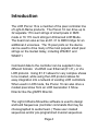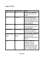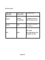
1
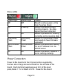
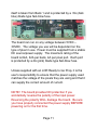
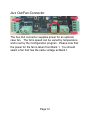
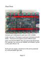
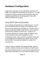
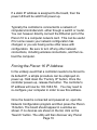
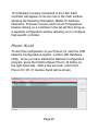
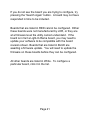
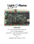
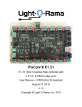
Pixcon 16 E1.31 16/32 Universe Pixel controller with 4 E1.31 to DMX ports User Manual August 6, 2015 V1.2 Copyright © Light O Rama, Inc. 2015 Table of Contents Introduction........................................................................4 What’s in the Box ..............................................................6 Applications: ......................................................................6 Hardware Fundamentals ...................................................7 Factory IP / Bootloader switches .....................................7 Power Connectors .........................................................10 Aux Out/Fan Connector.................................................12 Pixel Ports .....................................................................13 Ethernet Connector .......................................................15 LOR in/out and DMX Outputs (E1.31 mode only) .........15 LOR/ESTA Jumpers ......................................................16 Terminator jumper .........................................................17 Hardware Configuration...................................................18 Using DHCP (Normal Operation) ..................................18 Forcing the Pixcon 16 IP Address .................................19 Pixcon 16 List ................................................................20 Network .......................................................................22 Pixel Port Setup ..........................................................23 Advanced Port Configuration ......................................26 Misc.............................................................................30 Operation.........................................................................32 Startup...........................................................................32 Sending Data ................................................................32 Hardware Test Pattern ..................................................33 Firmware Upgrades .........................................................34 Physical Setup ..............................................................34 Obtaining New Firmware ...............................................34 Performing a firmware Update ......................................35 Operating Specifications..................................................37 Troubleshooting ...............................................................38 Status LEDs ..................................................................39 No Status or Power LEDs is On ....................................41 Controller does not appear in Find Pixcon 16 list ..........41 Light Outputs Not As Expected .....................................42 Introduction The LOR Pixcon 16 is a member of the pixel controller line of Light-O-Rama products. The Pixcon 16 can drive up to 32 separate 170 count strings of smart pixels in DMX mode or 16 170 count strings in Enhanced LOR Mode. The board can also act as an E1.31 to DMX bridge for an additional 4 universes. The 16 pixel ports on the device can be used to drive many of the most popular smart pixel strings on the market today, including WS2801 and WS2811. Command data to the controller can be supplied in two different formats: Via DMX over Ethernet (E1.31), or Via LOR protocol. Using E1.31 allows for very complex shows to be created, while using the LOR protocol allows for easy integration into a network of existing LOR controllers. When used in LOR mode, the Pixcon 16 can also drive a modest pixel show from an LOR Generation 3 Show Director like the g3MP3 Director. The Light-O-Rama Showtime software is used to design and build Sequences (controller commands that may be choreographed to audio/music.) These user created sequences and/or pre-programmed musical sequences Page 4 available from LOR and other companies are then arranged into Shows. These shows are played by your PC or one of the LOR Show Directors. Caution: Although most applications for this product use low voltages, this product may be used with dangerous DC voltages. Some connections may be at line voltage and potentially lethal. It is important that you have an understanding of electrical wiring. Page 5 What’s in the Box The Pixcon 16 comes with this user manual. The latest version of this manual is also available at www.lightorama.com ► Support ► User Manuals ► Pixcon 16 manual The Pixcon 16 can be used in multiple configurations. Additionally, the Pixcon 16 can be purchased as a separate device, or be included with an LOR Ready to Go prop. Applications: The Pixcon 16 can be controlled by an LOR G3 Show Director or a Windows PC. While being an advanced controller, the Pixcon 16 cannot be run in ‘standalone’ mode, and cannot be controlled by another LOR Controller in standalone mode. The Picon16 board itself is not weather resistant and needs to be mounted in a suitable weather resistant / weather tight enclosure. The enclosure to be used must have adequate ventilation. Connections are provided to Page 6 power a fan, and overheating of the board will cause damage to the components. Hardware Fundamentals Factory IP / Bootloader switches A factory reset should only be performed when absolutely necessary. The reset will erase all configuration and networking information which may be time-consuming to restore. To reset the device back to factory defaults, first remove power to the board. Then press and hold BOTH buttons while re-applying power. Wait a few seconds, then release the buttons. The board has now been reset back to factory defaults. Page 7 Since this is an E1.31 (Ethernet) device, you may need to re-set the IP address of the board to a known one. Remove power to the board, press and hold the Factory IP button, and then re-apply power. This will reset the board to the default IP address of 192.168.0.50. Release the button. If the firmware on the device becomes corrupted, you can recover the board by placing it in ‘bootloader’ mode. The bootloader mode allows the board to accept a new firmware which should fix the issue. Remove power to the board, press and hold the Bootloader button, and re-apply power. The Power and Status lights will alternate showing that the board is now in bootloader mode. Release the switch and use the Showtime Software to load the latest firmware. Should you need to reconfigure the board, or reload the firmware in emergency mode, the easiest way may be to connect the board directly to a computer’s network card via a CAT-5 cable. 1. Ensure no wireless network is active on the computer. 2. Shut down the computer and disconnect any existing network cable. 3. Power off the Pixcon 16. Page 8 4. Plug a CAT-5 cable directly from the adapter to the computer’s network card. A crossover cable is not required, any standard CAT-5 cable will work 5. Power up the board. Ensure the board is running correctly, or has been placed in the bootloader mode. 6. Turn on the computer and wait for it to fully boot. 7. Now start the LOR Network Configuration program and press the Pixcon 16 button. You should be able to find the board now to configure it, or to re-install the firmware. Page 9 Status LEDs Power Light Off Status Light Off On Flashing On On Alternating Flash Alternating Flash Synchronized Flash Synchronized Flash On Off Status Board is not powered, or the logic fuse has blown Board is powered on and running properly. No data signal has been detected Board is powered on, running correctly and is receiving data Board is in bootloader mode, and needs to have firmware uploaded Board is powered and waiting for an IP address from the DHCP server Board is powered, however it is not running correctly Power Connectors Power to the board and the 16 pixel ports is supplied by the two sets of large screw terminals on the left side of the board. Each terminal supplies power for 8 of the pixel ports, Bank 1: 1-8 or Bank 2:9-16. Power for the board Page 10 itself is taken from Bank 1 and is protected by a .5A (dark blue) blade type fast-blow fuse. The board can run on any voltage between 5VDC – 30VDC. The voltage you use will be dependent on the type of pixel in use. Power must be supplied from a stable DC source/power supply. The maximum rating of the board is 64A, 32A per bank, 4A per pixel port. Each port is protected by a 4A (pink) blade type fast-blow fuse. Unless supplied with an LOR Ready to Go Prop, it is the user’s responsibility to ensure that the power supply used matches the voltage of the pixels they are using and that it can supply the correct amount of current. NOTE! The board provides NO protection if you accidentally reverse the polarity of the input power. Reversing the polarity WILL damage the board. Be sure you have properly connected the power supply BEFORE powering on for the first time. Page 11 Aux Out/Fan Connector The Aux Out connector supplies power for an optional case fan. The fan’s speed can be varied by temperature and is set by the Configuration program. Please note that the power for the fan is taken from Bank 1. You should select a fan that has the same voltage as Bank 1. Page 12 Pixel Ports Connect up to 340 pixels to each port in E1.31/DMX mode, and up to 170 pixels to each port in Enhanced LOR Mode. The board can support several different pixel types, but all ports MUST have use same pixel driver/type. For example, you cannot mix WS2801 and WS2811 pixels on the same Pixcon 16. Each port can supply a maximum of 4A and is protected by a 4A pink blade type fuse. Page 13 Each port has a removable connector with 4 screw terminals. With the screws facing towards you and the wire connector points at the top (as if the connector is seated in the board, and you are looking at the connectors from the outside of the board), the pins are (left to right) 1 - + Power 2 - Clock 3 - Data 4 - Ground You should consult the manufacturer of the pixels you intend to use for correct wiring. For example not all pixel types use the CLOCK source. Page 14 Ethernet Connector Use this port to connect the Pixcon 16 to your network or computer’s network card. All configuration is done while the board is attached to a network via this connector. LOR in/out and DMX Outputs (E1.31 mode only) Page 15 The 2 RJ45 jacks labeled J3 and J4 can be used as an E1.31 to DMX bridge, or as input/output from a standard LOR RS485 network depending on configuration. The remaining 3 jacks labeled J5, J7 and J8 can be used as additional E1.31 to DMX bridge ports if the board is not running in LOR mode. LOR/ESTA Jumpers Whenever LOR equipment is in use on any of these RJ45 jacks, the jumpers must be moved from the ESTA side to the LOR side. LOR controllers, even in DMX mode, use a pinout that is different from other devices. Moving these jumpers sets the correct pins. Page 16 Terminator jumper Should you experience data transmission problems when using the Pixcon 16 on an LOR network, you may want to move this jumper from OFF to ON. Most networks will not require this. Page 17 Hardware Configuration Unlike other controllers in the LOR family, the Pixcon 16 MUST be configured via the Ethernet connection. It is not configured using the standard LOR Hardware Utility, but instead uses the Pixcon 16 configuration in the LOR Network Preferences program. Using DHCP (Normal Operation) Your network will typically have a DHCP server. It is the job of the DHCP server to assign an IP address to any device on the network that requests one. DHCP mode is always enabled by default on the Pixcon 16 so it should work with any network out of the box. However it is recommended that you assign a static IP address once communications have been established via the configuration utility. If the controller is in DHCP mode and is not assigned an IP address by a DHCP server, it will timeout after 15 seconds and default to a static IP of 192.168.0.50. If DHCP mode is enabled, both LEDs will flash together until the controller receives an IP address, at which point the power LED will remain on solid and the status LED will flash slowly indicating it is in run mode and ready for use. Page 18 If a static IP address is assigned to the board, then the power LED will be solid from power up. Typically the controller is connected to a network of computers/controllers/etc. either though a switch or router. You can however directly connect the Ethernet port of the Pixcon 16 to a computer network card. This can be useful if for some reason your network configuration has changed, or you are having some other issue with configuration. Be sure to turn off any other network connections, including wireless connections, and then reboot the computer. Forcing the Pixcon 16 IP Address In the unlikely event that a controller needs to be forced to its default IP, a simple procedure can be employed on power up. Hold down the “Factory IP” button. Once the controller powers up, release the button. The controller’s IP address will now be 192.168.0.50. You may need to re-configure your computer in order to see this address. Once the board is connected and powered on, open the Network Configuration program and then press the Pixcon 16 button. The board should appear in a window as shown. If no devices are shown in the list, click on the “Search” button. The utility will then discover any Pixcon Page 19 16 controllers currently connected to the LAN. Each controller will appear on its own row in the main window showing the following information: Model, IP Address, Nickname, Firmware Version and Current Temperature. Double clicking on a controller in the list will then bring up a separate configuration window allowing you to configure that specific controller. Pixcon 16 List To start the configuration of your Pixcon 16, start the LOR Network Configuration program, not the LOR Hardware Utility. Once you have started the Network Configuration program, press the Find/Configure Pixcon 16 button on the right hand side. After a few seconds, a list of the Pixcon 16 / E1.31 devices found will be shown. Page 20 If you do not see the board you are trying to configure, try pressing the ‘Search Again’ button. A board may not have responded in time to be included. Boards that are listed in RED cannot be configured. Either these boards were not manufactured by LOR, or they are at a firmware level the utility cannot understand. If the board is in fact a Light-O-Rama board, you may need to update your software to be compatible with the board revision shown. Boards that are listed in BLUE are awaiting a firmware update. You will need to update the firmware on these boards before they can be configured. All other boards are listed in White. To configure a particular board, click it in the list. Page 21 Network Here you can specify the static IP address and subnet mask that the controller will operate on as well as the type of IP connection. (Use DHCP to instantly see and configure the controller on any existing LAN.) To use the board with an ELOR (Enhanced LOR) network rather than in E1.31 mode, select the ‘J3/J4’ checkbox. Selecting this box will allow the board to be connected to a LOR Enhanced network at 500K speed and be controlled like all other LOR controllers. Each pixel port on the board should be given a unique Unit ID to avoid confusion. Page 22 Please note that while you can run the board in ELOR mode, even when connected properly it will not appear in the Hardware Utility if you search for controllers. The Auxiliary DMX ports allow for up to 4 E1.31 to DMX bridges. These are not enabled in ELOR mode. Please see the help documentation for the software for more information. Pixel Port Setup This window allows you to setup the pixel ports on the Pixcon 16. At a minimum you will need to select the type Page 23 of pixels you are going to connect, if they are high speed or not, starting universe/unit ID, and the triplet order. If more specific control is needed for your application, the “Advanced” checkbox can be selected. For more in-depth configuration information, please consult the help file provided with the software. LOR recommends that you assign a single DMX Universe or LOR Unit ID to a pixel port, rather than attempt to ‘Pack Pixels’. Using a single ID per pixel port will eliminate confusion. Select the type of pixel IC you wish to control. You cannot mix different pixel drivers (chips) on a single Pixcon 16 controller. For example you can’t run the WS2811 protocol on ports 1-8 and SM16716 on ports 9-16. All 16 ports must be of the same type. Pixel Drivers/Chipsets Supported The Pixcon 16 can currently support the following pixel drivers (chipsets): Page 24 WS2801 (standard LOR Pixels/Bulbs) WS2811/WS2812 APA102 LPD6803 MBI6020 MY9221 SM16716 Stella TLS3001 TM1803 TM1804 TM1809 Page 25 Advanced Port Configuration This allows for advanced configuration of the 16 pixel ports. Each port can be individually configured for its start universe, start channel, number of nodes (or pixels), null pixels, zig-zag and reversing. While the advanced configuration permits an extremely flexible channel setup, we recommend that you try to keep things as simple as possible and use a single Universe or Unit ID per port. The controller is capable of "connecting" Page 26 the beginning of an output to any channel within any universe. Outputs can be connected to the same universe data as each other, be sequential to each other, or even be separated by hundreds of universes if required. The key is to correctly match the universe outputs of your sequencer to the channel outputs you have configured for your controller. This can quickly become confusing. The Advanced Configuration can also quickly configure all higher ports on this device using the update buttons on the bottom. Again, LOR recommends one of the ‘One ID per Port’ options. Null Pixels Null pixels allow the controller to ignore or skip a specified number of pixels at the beginning of a given string or strip. This is useful when you want to extend your fixture, as the data signals in pixel strings and strips are not designed to travel over long distances. Each pixel has its own IC which actually re-buffers the entire data signal before passing it on to the next pixel. For example, by inserting some “null” pixels into a given length of cable before you get to the first pixel of the actual fixture, the digital signal will be buffered several times allowing it to reach the actual fixture some distance away (with the null pixels being skipped or ignored). Page 27 The other use for null pixels is when you may not want to use the entire string. In this case you can simply tell the controller to ignore or skip the pixels you don’t need. Zig-Zag Zig Zag allows pixel addresses to be allocated in a more logical order in the sequencer. For example, you may have a mega tree consisting of 16 strings of 50 pixels in your display. Starting at the first string, you would string pixels 1-50 from bottom to top, and then pixels 51-100 from top to bottom in the 2nd string and so on, zig-zagging up and down all the way around. When finished, if you turned the pixels on in order from the lowest address to the highest, you would see a pattern that started at the bottom of the first string and zig-zagged up and down as you move around the mega tree. When programming the pixels in the sequencer however, it’s much easier if the pixels light in a more intuitive order. In our example, we would use the zig-zag feature to tell the controller that the pixels reverse direction every 50 pixels. Thus lighting sequential pixels now produces the desired effect: the first string lights from bottom to top, then the 2nd string from bottom to top, etc. Page 28 Reversed Turning on the reversed option tells the controller to light the pixels in reverse direction on the fixture. This means the first pixel to light will actually be the last physical pixel in the fixture instead of the first physical pixel. RGB Order You can also change the RGB order of the pixel output. This is useful if the lights you are using are not physically wired in the standard red, green, blue order. Page 29 Misc Unit Name is available on all tabs. This allows the user to assign a custom nickname to the controller. The Misc tab allows you to perform a firmware update, change color correction values, set optional fan speed. The board’s current information including temperature and operating voltages are shown. The Firmware Update buttons allows the user to update the internal code running on the board. Please see the ‘Firmware Upgrades’ section later in this documentation. Page 30 Color correction is the method used for correcting the output of the LEDs so that they respond in a much more linear fashion when viewed by the human eye - the spectral response of the human eye is non-linear. This is particularly important when the LEDs are being faded, and also provides more accurate and vivid color representation. The optional Cooling Fan speed is set with the slider. The position of the slider determines when the maximum voltage is sent to the fan. For example, if you set the temperature to 95 degrees F, at or above 95 degrees the full will be on at 100%. At temperatures below 95 degrees, the fan will run at lower speeds. Please note that the fan’s voltage MUST be the same as the voltage used on BANK 1. Using an incorrect voltage fan could lead to failure or possible board damage. Page 31 Operation Startup Upon applying power, if you already have strings connected they may flash very briefly and then immediately turn off as the controller takes control of the pixels. If no data is being sent to the controller then the pixels will remain turned off until valid data is received. During normal operation the green power LED will remain on solid and the status LED will be on solid indicating the board is properly powered up and receiving a heartbeat from the Showtime Software. Sending Data Data is sent from the host machine to the controller via the LAN using E1.31 or “DMX over IP”. Please consult the Showtime Help File for configuration instructions, etc. Page 32 Hardware Test Pattern The controller features a built-in test pattern to assist in troubleshooting during an installation. To put the controller into this mode, press and hold the ‘Factory IP’ button for 3 seconds after the controller is already powered up and running. The controller will then enter the test pattern mode and will display red, green, blue and white sequentially in a repeating pattern on all pixels on each of the 16 outputs. Pressing the button while in this mode will then cycle through each of the four colors successively (on all outputs simultaneously) before returning to the current pattern again. To exit the test mode press and hold the ‘Factory IP’ button down again for 3 seconds and then release. Page 33 Firmware Upgrades The controller is capable of having its firmware upgraded. An upgrade is typically performed to fix any bugs that may have been overlooked in previous revisions or to add new features. Physical Setup To perform a firmware upgrade, ensure that you have your Pixcon 16 controller connected to the LAN network. Obtaining New Firmware Only use firmware that has been supplied by LOR for this device. Using any other firmware may damage the device or render it inoperable requiring it be sent back to LOR for service. The newest firmware will always be available on our website, http://www.lightorama.com Page 34 Performing a firmware Update WARNING: Ensure that NO OTHER programs are currently sending data to the Pixcon 16, including LOR programs like the LOR Comm Listener or LOR Tray. Failure to close all programs that may be sending data to the Pixcon 16 could put the board into a state that can only be recovered by using the Bootloader button. 1. Open the Network Configuration program. Click “Find/Configure Pixcon 16” and once the desired controller appears in the main window, click on it. 2. A configuration window will appear. Click on the “Misc” tab and then locate the “Upgrade Firmware” button and click on it. A “firmware update” window will appear. Click “browse” to locate the firmware file you wish to download. 3. Click on the “OK” button. 4. Once the download is complete, a message box will pop up saying it has completed successfully. 5. The controller will automatically reboot itself and then start running the new firmware application immediately. Page 35 If there is something wrong with the upgraded firmware, repeat the process again if it is still visible in the configuration utility. Otherwise, refer to the troubleshooting section for further information. Page 36 Operating Specifications The table below specifies the recommended operating conditions for a Pixcon 16 controller. PARAMETER VALUE/RANGE UNITS TOLERANCE Power Bank Input Voltage 5-30 V DC +/-5% Max Capacity Per Power Bank 32 A +/-5% Logic Current Consumption 5V DC 150 mA +/-10% Operating Temperature -40 to +60 -40 to +140 °C °F +/-5% A NA Individual Output 4 Current (Max) Page 37 Troubleshooting Generally, troubleshooting requires looking at the LEDs on the controller. There may also be a high voltage power supply connected to the board so extreme caution must be taken. Beware of ANY bare metal as it can be at LINE voltage. Unplug the power from the controller. Apply power again once the board is visible and the controller is in a safe position DO NOT TOUCH the inside components of the controller while power is applied, only look at the LEDs. If you want to change a jumper setting or a fuse, power should always be removed first. Power down as soon as you have finished troubleshooting. When in doubt, assume that a connection is at LINE VOLTAGE. Page 38 Status LEDs Power Light Off Status Light Off On Flashing On On Alternating Alternating Synchronized Flash Synchronized Flash On Off Page 39 Status Board is not powered, or the logic fuse has blown Board is powered on and running properly. No heart beat from the Showtime Software has been detected. Board is powered on, running correctly and is receiving data Board is in bootloader mode, and needs to have firmware uploaded Board is powered and waiting for an IP address from the DHCP server Board is powered, however it is not running correctly. Reset the board to see if the issue is cleared. If not, reload firmware. Ethernet jack: LINK LED (GREEN) DATA LED (YELLOW) CONDITION SOLID RAPID FLASHING CONNECTED OK, RECEIVING DATA SOLID OFF CONNECTED OK, NO DATA OFF NO LINK ESTABLISHED OR POWER IS OFF OFF Page 40 No Status or Power LEDs is On Ensure that the outlet you are plugged into is active. Check that the logic fuse has not blown. Ensure your power supply is supplying voltage correctly. Controller does not appear in Find Pixcon 16 list First, ensure you have the latest version of the LOR Showtime software installed. Ensure you have connected the board to a LAN and not to an LOR Network (USB adapter). Ensure the controller is in normal operating mode as per the LED codes. If you still cannot see the controller, directly connect the controller to the computer’s Ethernet jack. Ensure there are no other networks active on the computer, including any wireless networks. Reboot the computer and then power up the board. One final thing to check is your firewall. Ensure that it is not blocking network broadcasts from the utility. You may even need to disable it altogether while troubleshooting to ensure it is not causing an issue. Page 41 Light Outputs Not As Expected If the lights are not turning on at all then double check all power connections, fuses and light connections. Check the .5A mini blade logic fuse and 4A mini blade fuses on each output. If the lights turn on but are displaying colors you are not expecting, ensure the string(s) itself is not faulty by comparing to other known working strings if possible. Then verify the controller can be discovered using the utility. Ensure the string(s) has been programmed correctly in the LOR Showtime software. The DMX universe or LOR Unit ID must match the universe/UID assigned to the port along with the channel numbers. Be sure you have correctly set up your DMX universes using the Network Preferences program to use E1.31, or that you have set up the LOR network to use Enhanced mode at 500K. Check the status LEDs for more information and refer to section “LED Codes”. Page 42 Ensure you are using the correct voltage for the pixels that are in use. If there is no fault indicated by the LEDs check that your wiring of the lights is in accordance with the “Pixel Ports” section. Page 43 Light-O-Rama, Inc. Tel: (518) 539-9000 Fax: (518) 538-0067 [email protected]