1
LED Display Control System
User's Manual
Nanjing DBstar
Electronic Technology Co., Ltd.
October 18, 2010
Special instruction
instruction:
Thank you for your trust and support to our company. In
order to guarantee your use process smoothly, please read
the technical support manual before using the products.
2
CATALOG
Chapter I Hardware of LED's control system.................................................. 6
Section I Summarize.........................................................................6
1.1.1 Flow chart exlplanation of the fast application of the
synchronous system............................................................................6
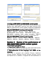
1.1.2 Type of DBT-Q2007 and DBT-Q2009 control system......... 11
Section II Review of the performance of DBT-Q2007/DBT-Q2009
control system..............................................................................................11
1.2.1 Function description.................................................................11
1.2.2 Recognition of the DBT-Q2007 and DBT-Q2009 hardware.
13
1.2.2.1 DBT-Q2007 full color sending card...........................13
1.2.2.2 DBT-Q2007\DBT-Q2009 receiving board (HUB
board)......................................................................................... 17
1.2.2.3 DBT-Q2009 receiving card (HUB board):................ 19
1.2.3 Recognition of the DBT-Q2007 and DBT-Q2009 software 20
1.2.4 Main performance index of the DBT-Q2009 receiving card.
31
1.2.5 Error detection function...........................................................32
Section III Temperature and humidity sensor................................41
1.3.1 The connection schematic diagram is as follows:............... 41
1.3.2 The application of the sensor in DBT-Q2007 synchronous
system................................................................................................. 41
1.3.3 Application of the brightness sensor in DBA-9.0
asynchronous system....................................................................... 42
1.3.4 The application of the brightness sensor in DBA-7.0
asynchronous system....................................................................... 43
Section IV Power control board......................................................... 44
1.4.1 Graphic of the real material is as follows:.............................44
1.4.2 2009 multifunctional board..................................................... 45
Chapter II Asynchronous control System..........................................................50
Section I DBA-9.0 asynchronous control system............................ 50
2.1.1 Summrize..................................................................................50
2.1.2 Function characteristics.......................................................... 50
2.1.3 Technical parameters.........................................................53
2.1.4 Issue list.............................................................................54
2.1.5 Hardware recognition.........................................................54
2.1.6 Introduction of the application method..................................56
Section II DBA-7.0 asynchronous control system........................ 66
2.2.1 Hardware recognition.............................................................. 66
2.2.2 Function characteristic............................................................ 66
2.2.3 Software introduction and application explanation..............67
2.2.3.1 Software introduction.................................................. 67
2.2.3.2 Software application....................................................68
Section III Video processor..............................................................80
2.3.1 Points for attention for safety................................................. 80
2.3.2 Hardware connection.............................................................. 81
2.3.3 Schematic diagram of the system connection..................... 81
2.3.4 Explanation of the keyboard key-press:............................... 82
2.3.5 Operation case.........................................................................87
3
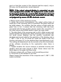
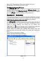
Chapter III Multimedia program and playing................................................. 89
Section I: Summarize....................................................................... 89
3.1.1 Function characteristic............................................................ 89
3.1.2 Operating environment........................................................... 89
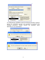
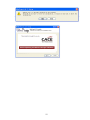
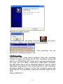
Section II Installation and unloading...............................................89
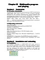
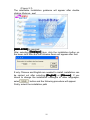
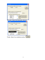
3.2.1 Installation.................................................................................89
3.2.2 Unloading..................................................................................94
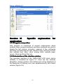
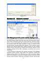
Section III Specific explanation for application..............................96
3.3.1 Program composition.............................................................. 96
3.3.2 Introduction of the interface window......................................96
3.3.3 Function introduction............................................................... 98
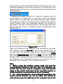
3.3.3.1 Menu bar: including file, edit, play, control, tool,
document and help。...............................................................98
2.3.3.2
Tool bar..................................................................108
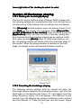
Section IV Edition of the program materials................................ 116
3.4.1 Operation of the project bar..................................................116
3.4.2 Adding program materials.....................................................119
3.4.3 Introduction of the material property................................... 120
3.4.4 Illustrations with example......................................................133
Section V How to play VCD/DVD/cd............................................ 134
3.5.1 Direct playing..........................................................................134
3.5.2 Playing in the program.......................................................... 135
Section VI How to play video input...............................................135
3.6.1 New-established program window...................................... 135
3.6.2 Setting the input window of the video................................. 136
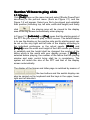
Section VII how to play slide............................................................ 137
3.7.1 Playing.................................................................................... 137
3.7.2 Stopping playing.................................................................... 138
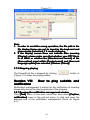
Section VIII How to play subtitle and notification........................138
3.8.1 Opening the notification management window..................138
3.8.2 Setting notification management window...........................139
3.8.3 Playing/stopping notification display................................... 139
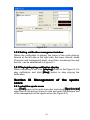
Section IX Management of the sports score.................................. 139
3.9.1 select the sports score.......................................................... 139
3.9.2 Setting the management of the sports score.....................140
3.9.3 Playing/stopping PE score................................................... 141
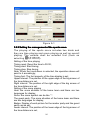
Section X Schedule........................................................................ 141
3.10.1 Opening timing instruction list............................................141
Section XI Network control............................................................ 142
3.11.1 Management of the remote real-time display screen..... 142
Section XII Backstage playing......................................................... 144
3.12.1 Starting the backstage playing.......................................... 144
3.12.2 Canceling the backstage playing...................................... 144
Section XIII Multi-screen combination..........................................146
3.13.1 Entering the synchronization of the multi-screen
combination...................................................................................... 146
Section XIV Software setting.........................................................149
3.14.1 Opening the setting of the software option...................... 149
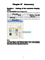
Chapter IV Accessory..................................................................................... 152
Section I Setting of the common display card.............................152
4
4.1.1 ATI-AGP/PCI series display card.........................................152
4.1.2 NVDIA series of display cards............................................. 153
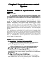
Section II manufacturing of the communication line..................... 156
4.2.1 Internationally standard type................................................156
4.2.2 Special explanation............................................................... 158
Chapter V Common problems.......................................................................160
Section I Synchronous control system.........................................160
5.1.1 Interruption of the connection.............................................. 160
5.1.2 No-signal output.....................................................................160
Section II Asynchronous control system......................................160
5.2.1 Failure to start normally........................................................ 160
5.2.2 Failure to send the content normally...................................161
5
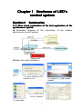
Chapter I Hardware of LED's
control system
Section I: Summarize
1.1.1 Flow chart explanation of the fast application of the
synchronous system
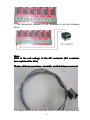
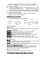
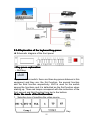
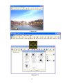
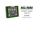
◆ Schematic diagram of the connection of the outdoor
synchronous control system:
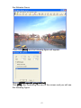
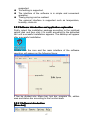
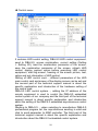
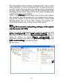
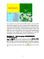
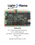
◆ Enter the control software:
6
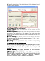
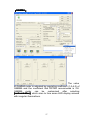
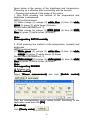
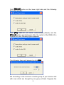
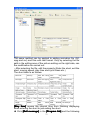
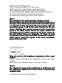
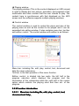
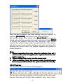
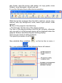
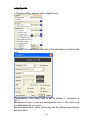
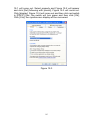
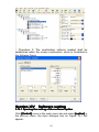
◆ Specific description of the establishment of the dialogue box of
the LED control system:
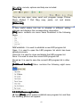
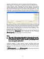
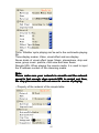
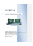
◆ Setting part of the sending card
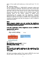
Screen display
[Screen
display] Adjust the brightness of the screen and the
scope is 1-256.
Position of picture
[Position
picture] Adjust the mode of the display and select
according to the resolution of the display. The area where the
content on the display is appointed shall be displayed on the LED
big screen.
[Screen rotation] The display content on the display will rotate
on the big screen of LED with the rotation angle 0℃, 90℃, 180℃
and 270℃ respectively.
[Schedule] time is appointed to carry out the corresponding
operation.
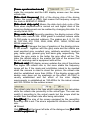
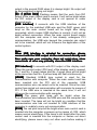
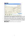
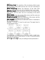
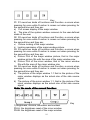
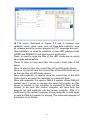
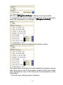
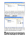
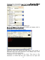
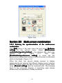
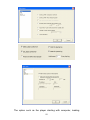
◆ Setting part of the receiving card
Before entering the establishment of the receiving card, it is very
necessary to understand the different contents of the receiving
setting interface to make the operation more simple and
convenient.
[Screen options] The basic parameter of the monolithic
receiving card shall be established.
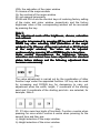
[LED driver] The driving chip type of the LED screen that the
receiving card is equipped with. The main supported driving chip
types: MBI5026/TB62726, MBI5027, MBI5030, MBI5039,
74HC595, LPD6803, DM413, MBI5042 and MBI5020.
7
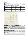
[Frame synchronized mode]
can
make the computer and the LED display screen own the same
refresh rate.
[Data clock frequency] CLK of the driving chip of the driving
screen, the scope is 4-225, that means the frequency scope of
the clock is 490KHZ-31.25MHZ.
[Data clock duty cycle] Means the data clock duty cycle of the
clock when displacement is carried out and higher clock of the
scanning displacement can be realized by changing this data. It is
usually set as 50%.
[Gray scale levels] Generally speaking, the display screen of the
double color selects 256. 4096 grade is selected indoors while
16,384 grade is selected outdoors. The grades are 4, 8, 16, 32,
64, 128, 256, 512, 1024, 2048, 4096, 8192, 16384, 32768 and
65536 respectively.
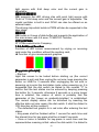
[Gray effect] Changes the lays of graphics of the display picture
of the screen together with the gray scale and the effects are
most excellent gray, excellent gray, relatively excellent, medium
gray, better gray, general gray and basic gray respectively. The
higher the gray scale is, the better the gray effect will be. The
lower the refresh rate is, the smaller the size of the screen that
the unit receiving card is equipment with will be.
[Refresh rate] LED display screen updates the rate of the picture.
The higher the refresh rate is, the more stable the frequency
image will be. If the ripple and scintillation intend to be avoided
when the camera is used to shoot the picture, the refresh rate
shall be established more than 600hz. If the display screen with
double color does not lay emphasis on the effect, 60-75HZ is
usually established and the effect of the color display
requirements is established as 180-600hz for the indoor screen
and 300-1200hz for the outdoor screen.
The refresh rate later is the type which undergoes the calculation
while the refresh rate previously is the actual type. The user can
modify it according to the actual needs but the scope shall be
smaller than the refresh rate after being calculated.
[Line][Row] The size of the screen equipped by the monolithic
receiving card is set. The size is adjusted to influence the refresh
rate.
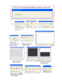
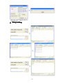
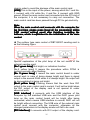
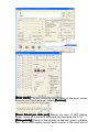
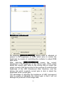
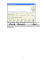
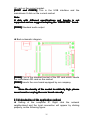
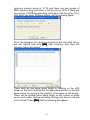
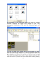
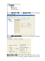
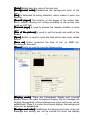
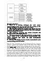
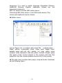
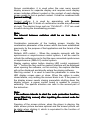
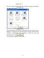
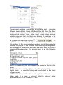
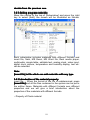
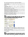
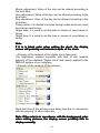
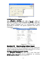
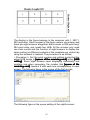
◆ Wizard
Click [Wizard] at the lower left side of the dialogue box [Set LED
…]
control equipment
equipment…
8
9
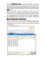
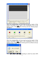
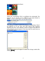
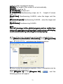
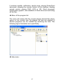
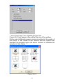
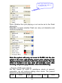
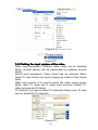
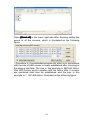
◆ Array setting
10
1.1.2 Type of DBT-Q2007 and DBT-Q2009 control system
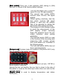
◆ DBT-Q2007 control system: DBT-Q2007 full color\double color
sending card, DBT-Q2007 receiving card, MINI receiving card,
DBA-7.0 asynchronous control system, brightness temperature
and humidity sensor, power control board and DVI distributor etc.
2007 receiving card supports]
[Chip that DBT-Q
DBT-Q2007
MBI5026、MBI5024、TB62726、TB595、MBI5027 etc.
◆ DBT-Q2009 control system : DBT-Q2009 sending card 、
DBT-Q2009 receiving card, video processor, DBA-9.0
asynchronous control system, multi-function control panel etc.
[Chip that DBT-Q2009 receiving card supports]
MBI5026、BI5024、TB62726、TB595、MBI5030、MBI5036、
MBI5039、MBI5042、MBI6030、MBI6020、DM413、LPD6803
Section II Review of the performance of
2007/
DBT-Q
2009 control system
DBT-Q
DBT-Q2007/
2007/DBT-Q
DBT-Q2009
1.2.1 Function description
◆ Supporting 10 digits of colors
The maximum number of the colors that DBT-Q2007\DBT-Q2009
system is 1024*1024*1024=1073741824 kinds of colors.
◆ Self-replacement of the language and LOGO of the
company
XMPLAYER is equipped with simplified Chinese, traditional
Chinese, English, Japanese, Korean, Russian, German, French
and Spanish etc. in addition; it supports the self-modification of
11
other languages and the self-replacement of the LOGO of the
company.
◆ Supporting multiple scan modes
DBT-Q2007 and DBT-Q2009 systems support: static, 2 scan, 4
scan, 8 scan, 16 scan and other scan modes.
◆ Supporting the driving chips with PWM
The coordination of the professional chip is entailed to make the
effect of the display screen more perfect.
◆ Supporting the point by point revision function of the
hardware
DBT-Q2009 system supports point by point revision which
supports single point, 2*2point, 4*4point and 8*8point the four
modes. The largest receiving card with single sheet supports the
revision of 128*128 point.
◆ Supporting the function of the error detection
DBT-Q2009 system supports the function of the error detection
but the coordination of the MBI5030\MBI5039\MBI5036 driving
chip is needed to dynamically inspect the flow situation of the
display screen.
◆ Gigabit technology
This is definitely the perfect gigabit. The standard of the sending
card with single sheet can own 1280*1024 resolution and the
maximum amount that it can take with is 2048*600 resolution.
The single net wire can utmost be equipped with 2048*300
resolution.
◆ Gigabit network card replacing the sending card and
display card directly
The gigabit network card can be equipped with point screen of the
receiving card instead of the sending card and display card
directly. Disadvantage: the configuration of the computer is
required higher (the usage rate of CPU is extremely high) and the
screen with smaller scope can be equipped with limited functions.
◆ Arbitrary setting of the gray and refresh rate
The clients can adjust between the non-gray and 65, 536 grade
(64K) gray arbitrarily according to the situation of the display
screen; the refresh rate can also be adjusted on a manual basis
to make your display screen reach the best display effect.
◆ Hot standby function of the double net wires
Both A and B port of the receiving card can be used as the input
or output, and they can also be used for two computers to control
the same screen. When one computer encounters some
problems, the other one will replace it automatically for controlling
12
or the double net wires of one computer can be used for
controlling. When one net wire encounters some problems, the
other one will replace it automatically for controlling to guarantee
the normal work of the display screen to the utmost.
◆ Sound transmission function
DBT-Q2009 sending card integrates the sound transmission
without the need of audio line additionally to transmit the sound to
the display screen. Double 24 bit 64 khz high fidelity digital
signal→ analog signal and analog signal → transformation of the
digital signal to make the image effect of your display screen
perfect.
◆ Ultra-long transmission distance
The longest distance of the transmission is 160 meters (actual
measurement) and the reliable transmission distance can be as
long as 130 meters. When surpassing 130 meters, we suggest
using the fiber transmission. When the transmission distance is
between 130 and 1, 000 meters, it is suggested to use the
multi-mode fiber transmission; when the transmission distance is
more than 1, 000 meters and less than 10, 000 meters, we
suggest to adopt the single-mode fiber for transmission. (Note:
Since our system adopts gigabit transmission, the fiber
transceiver we use shall also be gigabit type).
1.2.2 Recognition of the DBT-Q2007 and DBT-Q2009
hardware
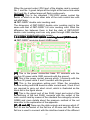
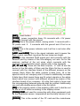
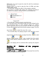
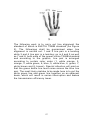
1.2.2.1 DBT-Q2007 full color sending card
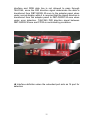
◆ DBT-Q2007 main control card (sending card is built in) is
illustrated in the following figure:
The explanation illustrated in the figure is as follows:
13
[B1] Standard PCI interface is used for inserting into the PCI slot
of the computer; there are three interface kinds between our main
control card and the computer and they are PCI interface, USB
interface and RS232 interface respectively. Since the RS232
interface among them is seldom equipped in the current compute,
we have shut down our production and the user can give an order
when necessary. The internal type mostly adopts PCI
communication nowadays while the external type uses USB
communications.
[J201] Standard DVI interface is connected by the matched DVI
wire and DVI interface of the display card of the computer. There
are four lamps among which two are in green color and yellow
color respectively on the side of the two RJ45 outputs. Only a
yellow lamp in the middle will flash after connecting with the DVI
output of the display card. The two green lamps will be bright, the
yellow lamp in the middle will flash slowly while the yellow lamp
along the side will flash quickly only when the second output of
the display card of the computer is opened. More details about
how to open the second output of the display card refer to the
manual of the display card purchased or the settings of the
display card in the appendix.
[JP501] Is the data transmission port of tow RJ45. The one next
to the USB interface is the first output following with the second
one which is connected by the standard five-category net wire
and the input of the HUB scan board. One transmission port is
able to transmit 640 rows of data to the utmost (different screens
own different row parameters on how many rows are equipped).
The baffle that RJ45 and DVI correspond to is as the following
figure:
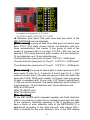
Special explanation of the pilot lamp at the net mouth of the
sending card:
[No. 1 green lamp] Not bright, no indication function
[No.2 yellow lamp] It means the procedure within FPGA is
working normally when flashing.
[No.3 green lamp] It means the main control board is under
normal work in case of being always bright and there is signal
14
output in the second RJ45 when it is always bright. No output will
be demonstrated in being not bright.
[No. 4 yellow lamp] Flashing means that the work from DVI
output to the main control card is normal. It will not be bright when
the DVI output of the display card is not opened or under
abnormal work.
[USB interface] It connects with the USB interface of the
computer by the matched USB wire and the D601 green pilot
lamp on the main control board will be bright after being
connected, which means USB interface is normal; it will not be
bright without connection. When the main control board inserts
into the computer and since it has already undergone PCI
communication, the USB wire beyond the computer can select
not to be inserted, which will not influence the application of the
control system.
Note:
When USB interface is adopted for connection, please
connect with the USB output on the main board directly and
then make sure your computer does not exist virus, since
some kinds of virus may probably close the USB interface.
[DVI interface] It connects with DVI output of the display card.
When the second output (DVI) port of the display card is opened,
No. 1 and No. 3 green lamps and No. 4 green lamp will be bright
at the same time and No. 4 yellow lamp will flash continuously.
[JP602] Standard USB-B type socket is used for the
communication with computer. When the main control card has
been inserted into the PCI slot of the computer, USB
communication wire can select not to be inserted. Since the main
control has carried out communication with computer by means of
PCI. If the USB wire is inserted at the same time, it will not
influence the communication with computer.
[D601] The green pilot lamp will be bright when the
communication wire between the USB wire and the computer has
been inserted. The lamp will not be bright on condition that the
communication wire has not inserted or USB interface of the
computer is unable to carry out communication.
[D102] The red pilot lamp will be bright when main control card is
inserted into the computer or powers up by means of J102, which
means normal electrifying. If the lamp is not bright after the main
control card is inserted into the computer or carries out direct
electrifying, please never carry out other work before making it
15
clear in order to avoid the damage of the main control card.
[J102] This is the input of the power, among which No.1 and No.
3 connect with +5V while No. 2 and No. 4 connect with GND
ground. When the main control card is inserted into the PCI slot of
the computer, it is not necessary to carry out connection. The
main control card has been passed through PCI to get electricity.
Note:
When the main control card connects with the computer for
the first time, please press [send all the parameters] within
[LED control setting] panel after finishing installing the
software, which is equivalent to the initialization of the main
control.
◆ The outdoor type main control of DBT-Q2007 sending card is
as the following figure
Special explanation of the pilot lamp of the net mouth of the
external sending card:
[No.1 green lamp] Not bright, no indication function
[No.2 yellow lamp] It means the procedure within FPGA is
working normally when flashing.
[No. 3 green lamp] It means the main control board is under
normal work in case of being always bright and there is signal
output in the second RJ45 when it is always bright. No output will
be demonstrated in being not bright.
[No.4 yellow lamp] Flashing means that the work from DVI
output to the main control card is normal. It will not be bright when
the DVI output of the display card is not opened or under
abnormal work.
[USB interface] It connects with the USB interface of the
computer by the matched USB wire and the D601 green pilot
lamp on the main control board will be bright after being
connected, which means USB interface is normal; D601 will not
be bright without connection. The USB wire of the external main
control must connect with the computer, otherwise all the
changed parameters in the display screen will fail to be used.
[DVI interface] It connects with DVI output of the display card.
16
When the second output (DVI) port of the display card is opened,
No. 1 and No. 3 green lamps will be bright at the same time while
No.2 and No. 4 yellow lamps will flash continuously.
[POWER] This is the standard 110V-220V power socket the
switch of which is on the other side of the main control box with
red pilot lamp.
◆ DBT-Q2007 double color sending card:
The dimension of DBT-Q2007 double color sending card is the
same with that of DBT-Q2007 full color sending card. What the
difference lies between them is that the data of DBT-Q2007
double color sending card can only pass through USB interface
and support single\double color screen.
1.2.2.2 DBT-Q2007\DBT-Q2009 receiving board (HUB board)
◆ DBT-Q2007 receiving board (HUB board):
[J1] This is the power connection base. 5V connects with the
positive 5V power while GND connects with the ground.
[J2] This is the power socket, among which 1 connects with the
positive 5V power while 2 and 3 connect with the ground.
[J4] This is the procedure writing port. When the procedure
finishes writing and HUB board is under normal work, 2 and 4 foot
are required to carry out short circuit, which is illustrated as the
black dot in the figure above.
[J6] This is the signal port of two RJ45 (input and output of the
self-defining of the two RJ45) connects with the output of the
main control card by means of the standard five-category net wire
(508B) and more details about the pressure method of the net
wire refer to the explanation of the appendix.
[J7, J8 and J9] These are the data outputs and among which J7
and J8 are the socket of the flat line of 50-core and the 50-core
flat line is used to connect with the interface board of the different
17
screens on the market. Each 50 flat line outputs 8 data lines. J9 is
the special kind of our company and it is used to additionally
increase 8 data lines (that means there are 24 output signals on
the whole board which can connect with different screens by
means of the interface board of our company. J8 is the first output
of scan and the corresponding between grounds shall be noticed.
Additionally, one end with double-arrow mark is the first stitch;
[JP1] Is the polarity switch of the enabling (OE) and it shall be ON
status under the normal working conditions.
[SW1] Is the measurement button of the display screen and
under the condition without connecting with the main control, the
display screen will appear all red, all green, all blue and gray
these kinds of measurements only by keeping pressing the button
for 3 seconds. The image will switch between the red, green and
blue vertical line and the inclined line by pressing for twice
continuously under the status that the measured image appears.
The measurement mode will be end only inserting the net wire on
the RJ45 port.
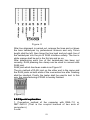
1.2.2.3 DBT-Q2009 receiving card (HUB board):
◆
Structure
and
working
condition
of
the
hardware
Rated voltage:5V+0.3V;
Rated current:3A;
[Fin]
Gigabit transmission chip RTL8212
(one chip for one card). Fin is
needed to be pasted.
18
[Dial switch] There are 4 dial switches (DIP) dialing to [ON]
direction in course of the factory default settings.
The first dial switch (DIP1) controls
upper 50-core OE signal polarity;
The second dial switch (DIP2)
controls lower 50-core OE signal
polarity
(When getting electricity, that the
dial switch controls OE signal
polarity is valid and OE polarity
fails to be adjusted by dialing the
dial switch after getting electricity.
The purpose of such design means
to avoid the phenomenon of the
LED display screen reversing
these OE polarities burns the line
output transistor when getting
electricity);
The third dial switch (DIP3) is used
in the function of the receiving card
measuring LED module groups
and more details are illustrated in
the following page;
The forth dial switch (DIP4) has not
been used temporarily;
[Jumper cap] 2 jumper caps are needed in the place of 601 (only
one is needed in the earlier version):
[Transmission net wire] National standard net wire, CAT5E or
more excellent materials;
Among the two net mouths, the one that is closer to the side of
the power is used as the data input while other one acts as the
cascade output;
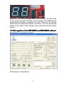
[Digital tube] Is used to display temperature and status
information;
19
When there is effective image data in the net wire, the pilot lamp
of the receiving card will flash and the digital tube displays the
temperature normally; otherwise the pilot lamp will be always
bright and the digital tube flashes, moreover, it will be closed and
output to the signal of the display screen which will become black
screen;
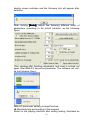
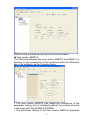
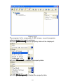
1.2.3 Recognition of the DBT-Q2007 and DBT-Q2009 software
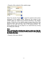
◆ Software for parameter setting
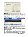
◆ Parameter interpretation
20
[Data clock
frequency] Corresponds with LED driving chip such as
MBI5026/MBI5030 data clock frequency DCLK and it shall be
noticed that within the frame (62 of the previous figure) is the
frequency division number with respect to the internal clock
125MHz. The frequency display of DCLK is beside (such as
10.41MHz=125MHz/12 frequency division in the figure above);
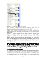
[Data clock duty cycle] Is the one of the [data clock frequency]
DCLK and open it by clicking:
The adjustment of the [data clock duty cycle] here can not only
applied to the data clock duty cycle of the clock. The location of
the high level of the clock also needs changing, which is practical
to some LED screen;
[Polarity reversed-phase of the data clock frequency] The
high level of the clock will become the low level and vice verse
after selecting the option;
[Latch signal space] One latch signal pulse shall be realized to
make the data store in the data buffer of the LED driving chip for
the purpose of continuing the next data transmission after LED
driving chip finishes the data transmission for once. The time
interval between the twice data transmission, which means the
time giving for the latch signal pulse, is the [latch signal space]
space];
21
[Pulse width] The same with [data clock duty cycle] of the
[data clock frequency]
frequency], the latch signal pulse width is also able
to adjust the data clock duty cycle and the location of the high
level;
[De-shadow time] As for the scan screen, since the LED driving
chip is used among several rows and the through display
completion of the data in the previous row has to be waited before
the data in the next row is input, the waiting time is [de-shadow
time]
time].
[Gray scale] Means the gray scale that can be indicated and
what it represents is the bit number of each color of the
characterization. Taking the figure above as an example, the gray
scale is 4,096; it means that each color utilizes 12 bit
characterization.
(2^12=4096);
[Gray effect] Is the unit time number of the maximum bit of the
characterization color displaying in the LED.
“Most excellent gray”: The maximum characterization of the color
displays 64 unit time
“Excellent gray”: The maximum characterization of the color
displays 32 unit time
“Relatively excellent”: The maximum characterization of the color
displays 16 unit time
“Medium gray”: The maximum characterization of the color
displays 8 unit time
“Better gray”: The maximum characterization of the color displays
4 unit time
“General gray”: The maximum characterization of the color
displays 2 unit time
“Basic gray”: The maximum characterization of the color displays
1 unit time
“Refresh rate” means the repetitive display frequency of the same
image in LED display screen and under “frame synchronized
mode", the value is the multiple of the frequency 60Hz of the
image of the display card while under the non-frame
synchronized mode, the value will be the average display
22
frequency of the image instead of the multiple of 60Hz.
[Row/line] This is the regulated pixel area to display the image of
the single receiving card;
[Brightness loss] The brightness loss with respect to the LED
tube when it is always bright is the loss of the time domain, which
means that LED tube does not own the lightening time capacity;
brightness loss results from the occurrence of gray;
[10 bit data source] Means what the sending card transmits to
the receiving card is the 10b high definition video source and the
common DVI data is 8b video source;
[HUB data conduplication] Means that the 50-core data in the
upper and lower of the receiving card controls the right and left
half part of the LED display screen respectively instead of
controlling the upper and lower half part of the LED display
screen generally; meanwhile guaranteeing the refresh rate, such
connection sacrifices half vertical loading areas with twice
horizontal areas;
[data on mirror] Represents mirror image of the image on the
right half part of the forward-looking of the LED display screen. At
this time, the right half part of the forward-looking of the LED
display screen is driven in from the left side while the left half part
is driven in right side;
[line before gray] Under general circumstances, scan screen
starts to scan gray following with rows and the reason why it is
carried out like this is to reduce the times of row changing of the
data; [line before gray] displays that the visual effect is evener
than the former one, the image is stable while the shortcomings
are that it influencing closing the row and the shadows among the
rows are difficult to eliminate;
[Power on gradually-brighten] The function produces the effect
from being dark to bright when the LED display screen powers up
and the reason why it does like this aims to avoid producing
excessive power load due to illumination meanwhile all the LED
tube are powered up.
[Left driving of the data] Under general circumstances, the data
displayed on the LED display screen is right driven in form of the
forward-looking and selecting the option means the data of the
LED display screen is left driven.
[Receiving setting]
23
[Scan mode] The line scanning specification of the scan screen
supports non-standard scan (select [Custom]
[Custom]).
[Rows drived per data port] Means the rows of LED display
screen driven by a group of GRB and the maximum row is 32;
[Data polarity] Points to the polarity of the red, green and blue
data. Some LED display screen adds inverter in the input end of
24
RGB data;
[Color order] Means the corresponding relationship of the RGB
arrangement on LED display screen and the RGB on the 50-core
of the receiving card;
[Scan decoding type] “138/139”: Decoder decode
“Full-decode”: Without decoder, supporting 4
scan full-decode utmost
“CD4094/595”: Shifter;
[OE mode] This is the control mode of OE polarity, “using
hardware control" means adopting the dial switch DIP1/DIP2 on
the receiving card for selection and “positive mode/negative
mode” points to the OE polarity of the software control;
[LED driver] The driving chip which is adopted by the LED
display screen is selected;
[Minimum OE pulse width] The minimum pulse width which is
able to response when corresponding to the driving chip can be
filled in;
[24 groups of data modes] the receiving card is able to output
24 groups of RGC data utmost to make the vertical loading area
50% more than that of the competitors (pinboard of the 24 groups
of RGB data signal is entailed);
[90
[90°°image rotation] It will facilitate LED screen flip when the
picture rotates 90 degrees;
[Gray order] The display order of the bit number of the
characterization RGB data on the LED display screen means that
either displaying the low bit gray or high bit gray can be
accessible for the precision adjustment of the display effect of the
screen;
[Row order] It is allowed that LED display screen is arranged
arbitrarily between 16 rows, which can facilitate the cloth plate of
the LED display screen. It also applies to some special
application, such as the data transposition between RGB data
groups;
[64 row mode] "Row order” has 64 order items after being
selected and each of them is the extension of the previous item;
[Data path]
25
Data path is the order of dot drawing when “wizard is carried out
and it reflects the routing patterns of the LED module group
(maximum 256 pixel arbitrary routing). The parameter will be
produced automatically after the wizard is finished and it is not
necessary for modification under general conditions;
26
GAMMA
【GAMMA
GAMMA】
The value
of GAMMA meter is adjusted by regulating coefficient (1.0-4.0) of
GAMMA and the coefficient that DSTAR recommends is 2.8.
GAMMA meter
can
be
customized
after
selecting
[customization]
[customization], which aims to face some LED display screens
with irregular illuminations.
27
[Light tube]
The parameter of the light tube is the serial rules of the LED
display screen which establishes red, green and blue serial
transmission and the vacuum point and repetitive point are
allowed, which means the pin on the corresponding driving chip
can choose not to connect with LED luminescent tube or the LED
luminescent tube on multiple pins of the driving chip can display
the same point etc.
[Group end] represents the cycle end of a pixel point;
28
[Brightness adjustment]
No selecting [MBI5030/MBI5039] means what is adjusted at
present is the brightness of PWM which aims to control the
brightness by means of controlling the multiplier to adjust RGB
data value;
After selecting [MBI5030/MBI5039] means the current
adjustment is the brightness of the current gain (CGA) which
sends the current gain value to the driving chip to control the
output current of the driving chip for the purpose of controlling the
brightness of the LED luminescent tube, therefore, only the
driving chip which supports current gain is able to adjust the
brightness of the current gain;
The advantage of adjusting the brightness of LED luminescent
tube by means of adjusting the current gain is that it will not
damage the perfection of the image data;
29
Selecting [Collecting data] means the brightness results from
the brightness sensor at the serial port of the connection
computer, in this way, that the brightness of LED display screen
can be adjusted according to the brightness of the environment is
realized and the related configuration can be checked by opening
[Set] button.
Another automatic brightness adjustment mode with sensor
carries out series connection with a DSTAR multifunctional card
in the queue of the receiving card (the function such as audio
transmission, temperature and humidity sensor and power control
are possessed), the function card collects brightness
automatically and then sends to the receiving card to realize the
automatic adjustment of the brightness.
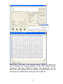
[Queue setting of the receiving card]
Queue of the receiving card is the arrangement order of the
receiving card of the mutual cascade controlling LED display
screen and it is used to set the image area controlled by different
receiving cards.
Click [Insert] to establish a queue of the receiving card:
30
The net wire cascade order of the value characterization on the
receiving card in the figure
Open [Brightness adjust] after selecting s`ome receiving card
and the correction parameter can be independently sent to the
receiving card:
The monolithic receiving card supports the brightness correction
or chroma correction with 128*128 pixel area to the utmost;
The current correction mode can be selected: brightness
correction and chroma correction;
The correction of some receiving card can be opened/ closed
independently;
The correction of the red, green and blue color can be established
individually and the four-color correction can be set independently
under the virtual pixel;
The correction parameter can be derived from save or introduced
to the saved correction parameter or the correction information of
the third pane;
Point by point parameter correction is an 8-bit data with the 0-255
number range;
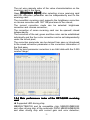
1.2.4 Main performance index of the DBT-Q2009 receiving
card
◆ Supported LED driving chip:
MBI5026/TB62726 and its compatible chip; MBI5030/MBI5042
and other driving chip of the automatic PWM; MBI5036/MBI5039
and other driving chip with current gain and error detection;
31
MBI6020/DM413/LPD6803 and other driving chip of the electric
light source;
◆ Maximum data group number: 24
� Maximum driving row number of a group of data: 32 rows
� Maximum line scanning: 32 scanning
� Maximum loading pixel area of the single receiving card:
� Full color: 2, 048 line *256 row (16 groups of data) or 1, 024
line *384 row (24 groups of data);
Double color: 2, 048 line *512 row;
Minimum OE pulse width: 8ns;
� Maximum frequency of DCLK: 125MHz / 4 = 31.25MHz;
� Maximum pixel area of the drawing dot: 256;
� Maximum gray grade: 65, 536 grade (16 bit);
� Adjustment grade of the PWM brightness: 256;
� Adjustment grade of the current gain: 256;
� Light tube control (RGB data serial): supporting the vacuum
point and repetitive point within 64 point pixel;
� Revision of the point by point brightness/ maximum pixel
area of the chroma correction: 128*128;
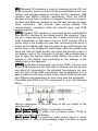
� Maximum pixel area of the error detection: 512 point* line
scanning* 16
� Returning path error detection of 16 groups of data:
The loading area will not be influenced and 20pin extended port is
utilized to pass back the error detection data;
The upper and lower
50-core contain 16 groups
of RGB data which are used
for controlling the display of
the LED screen. The
extended port of 20 core on
the right contain pass-back
data which come from a
pass-back data group while
the selection board is used
to select one group in the 16
groups of the pass-back
data. Error detection is
carried out and passed back
group by group.
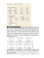
1.2.5 Error detection function
32
◆ The driving chip that supports error detection function
[MBI5036] supporting the error detection in information
[MBI5039] supporting 3 kinds of error detections
[MBI5030] supporting the inspection of the open circuit and
short circuit
Note:
The error detection of the MBI5030 differs from that of the
MBI5036/5039
�
Connection graphic of the error detection and points for
attention
Three kinds of connection methods of the error detection of
DSTAR DBT-Q2009:
[8 port detection]
33
[12 port detection]
[16 port detection] [Selection board of the pass-back data] is
entailed and DBT-Q2009 extended port shall be connected. (20
[selection board of the pass-back data] function is to
core)[selection
select one group among 16 groups of R0GBR1 data which are
passed back by the LED screen by means of 74HC152 (select 1
from 16 groups and the selection signal is offered by DBT-Q2009
20 core extended port) to finally connect to the DBT-Q2009 20
core extended port.
The upper data line is transferred among DBT-Q2009 50-core
34
interface and RGB data line is not allowed to pass through
74HC245, since the DIR direction signal determines the data is
transferred from DBT-Q2009 50-core to the adapter panel when
under normal display while it is required that the signal direction is
transferred from the adapter panel to DBT-Q2009 50-core when
under error detection. 74HC245 DIR direction signal between
DBT-Q2009 50core and FPGA is controlled by procedure.
◆ Interface definition when the extended port acts as 16 port for
detection
35
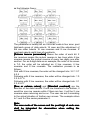
◆ Detection pixel point (The pixel area that one block of the
DBT-Q2009HUB can be detected)
[Static screen] a group of data (One data port) can detect pixel
point 512*4 (The static screen carries out detection with four
times automatically), that means if one group of data of the
screen is equipped with 8 row high, 512*4/8 = 256 row can be
detected. The overall detection point number of 8 port detection,
12 port detection and 16 port detection are:
“Overall detection pixel point of 8 port” 512*4*8 = 16384 point
“Overall detection pixel point of 12 port” 512*4*12 = 24576 point
“Overall detection pixel point of 16 port”
512*4*16 = 32768 point
[Scan screen] one group of data is able to detect pixel point 512*
scan mode (2 scan for 2, 4 scan for 4 and 8 scan for 8…), that
means 8 screen scan (1/8 scan) one group of data can detect the
point with 512*8= 4096 point number. If 8 screen scan one group
of data is equipped with 16 row high, 512*16(post high)/8(scan)
=1024 row can be detected. The overall detection point number of
8 port detection, 12 port detection and 16 port detection are:
4096*8=32768 point
4096*12=49152 point
4096*16=65536 point
[Detection time]
All the DBT-Q2009 which cascaded together can finish detection
within 4 seconds but certain time is needed to pass back the data
to the computer. Generally speaking, 2-10s is needed to pass
back a block of error detection data of the DBT-Q2009 (it is
determined according to the data amount), that means 200-1,
000s is entailed for the error detection time of the LED display
36
screen composed of 100 blocks of DBT-Q2009 for once (4-17
minutes)
[Influence of the error detection to the normal display of the
big screen]
As for the detection of In-Message, MBI5036/5039 actually can
never influence the normal display totally, however, it fails to
detect all the errors for once, since In-Message detection requires
that display data is ’1’ and OE is in low level, which means that
only the luminescent tubes can be detected. When it is in normal
display, it is possible that some luminescent tubes are not bright.
In order to detect all the errors in one time, DSTAR DBT-Q2009
adopts the method of forcing the data to be placed ’1’ and OE is in
low level, however, if doing so, the normal display (LED display
screen will turn white instantly) will be affected instantly in course
of detection.
As for the forced error detection, since MBI5036/5039 adopts the
method of opening the LED instantly for detection, the influence
of the DBT-Q2009 receiving card to the LED big screen is very
small in course of the detection.
[Points for attention of the shield design]
○ The driving chip of many scan screen OE are grounded, which
directly results in the failure to carry out “forced open-circuit
detection” and “forced short circuit detection”. Therefore, the
method of making the driving chip grounded is not recommended.
○ The advantage of the LED driver which supports the built-in
PWM of the built-in PWM driving chip:
○ The update time of the image data is reduced to enhance the
update rate of the image data;
○ The visual refresh rate of the LED display screen is enhanced
(special PWM accounting algorithm);
○ Extremely excellent and low-gray representation (without the
response problem of OE pulse width).
Note:
Taking MBI5030 as an example
37
[Parameter interpretation]
The gray scale of PWM: The digit capacity of the bit of the
characterization RGB with deep color decides the range of the
PWM counter;
Count mode of the PWM: the S-PWM technology specially
possessed by MBI can enhance the visual refresh rate
dramatically;
Synchronous mode of the PWM: the scan screen forces “manual
synchronization” and the static screen suggest “automatic
synchronization";
GCLK frequency: The clock frequency is the same with that of
DCLK when PWM carries out counting and the value within the
frame is frequency division number with respect to 125MHz;
[Points for attention for the parameter configuration]
○ As for the scan screen, DCLK and GCLK need certain linkage
due to the interior requirements of the driving chip with PWM,
thus, when the adjustment of one frequency will influence that of
another and the algorithm is automatically calculated by the
software; The static screen does not have such problems;
○ As for the scan screen, it is generally suggested that [PWM
count mode] is set as [00] to enhance the refresh rate
dramatically. “PWM gray scale” is suggested to establish as
“12bits” (4096 grade scale), which is also beneficial to achieving
relatively ideal refresh rate. This of course can be determined
according to the actual situation; the static screen is adjusted
according to the requirements;
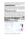
○ As for the scan screen, the refresh rate displayed on the
software (illustrated in 600Hz in figure above) is the data update
38
rate and the multiple of the visual refresh rate produced by
S-PWM is beyond calculation. Since to the scan screen, data
update rate makes greater contribution to the visual refresh rate;
as for the static screen, the refresh rate displayed on the software
has calculated the multiple of the S-PWM refresh rate, therefore,
the refresh rate of the static screen usually can reach thousands
of values;
○ [Latch signal interval time] and [de-shadow time] can
establish smaller value, illustrated in 2;
○ Order of the parameter configuration: select the driving chip->
set the row, line and scan mode etc. of the loading of the
receiving card-> set “PWM gray scale” (“12 bits is suggested to
be used) and “PWM count mode” ("00" is suggested to use) ->set
proper GCLK frequency->carry out fine adjustment to DCLK to
match with GCLK;
○ The scan screen which builds in the PWM driving chip does not
support “scan row following with gray”;
○ 24 groups of data output is not supported when the PWM
driving chip is built in and only 16 groups of data output is
supported.
○ Application of the MBI5030/MBI5042 on RGB serial LED
display screen (color curtain and light tube):
Since the driving chip which builds in PWM reduces the update
time of the image data significantly, data transmission can be
carried out even though DCLK operates under a very low
frequency while both the visual refresh rate and image quality
represent well, therefore, the application of it in RGB serial LED
display screen becomes the ideal choice and the effect is much
better than the common driving chip with the constant current
source (such as MBI5026);
DSTAR DBT-Q2009 (DBT-Q2009) LED control system supports
MBI5030/5042 and the application of other driving chip with
interior PWM on RGB serial LED display screen as well as the
vacuum point and focal point;
○ Other LED driving chip which builds in PWM (mainly with point
light source):
LPD6803
Only the LED driving chip of the point light source with 5-bit deep
color is supported and used in the low-end application with
relatively low color requirements. Moreover, crystal oscillator is
built in;
DM413
The crystal replacement supports the LED driving chip with point
39
light source with 8-bit deep color and the current gain is
adjustable;
MBI6020/MBI6030
MBI supports the LED driving chip with point light source with
16-bit or 10-bit deep color and the current gain is adjustable. The
crystal oscillator is built in and GCLK can also be offered on an
external basis;
The driving chip which builds in PWM will also be supported in the
later stage:
MBI5050
MBI builds in 8 rows of data buffer and supports the application of
the scan screen with 2-8 scan; TC62D722: Toshiba;
STP1612PW05
ST STMicroelectronics Company;
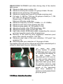
1.2.6 Additional function
Function of LED screen measurement by relying on receiving
card under the condition without the sending card;
◆ Function of give measurement graphics
[Key-press principle]
○ Start-up:
Light the screen to be tested before starting up (the correct
parameter is set) and then unplug the net wire; keep pressing the
button on HUB for 3 seconds after unplugging the net wire or
powering up to enter the test states (note: when powering up, it is
suggested that the dial switch be dialed to the number “2” to
ensure that the test states can be entered by keeping pressing
the button for 3 seconds, otherwise 9 seconds or a more longer
time is entailed, the reason of which is probably that the
parameter of the “power on gradually-brighten” is established.
The normal display status can be achieved by inserting the
effective data net wire again (the dial switch 2 shall be dialed to
‘ON’ direction at this moment);
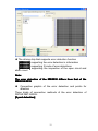
○ The defaulted test graphic is in red color after entering the test
states.
○ Key-press shall be finished within 1 second for each time and
the interval time for key-press shall be at least 2 seconds;
○ Once or twice is feasible for key-press in each time and the
representative meaning is that: when the dial switch 2 is dialed to
40
ON direction:
Pressing the key for once: cycle stepping is carried out in 5
measurement examples;
Pressing the key for twice: pause/restart (it will remain the current
measurement example and the picture is made to move by
pressing for twice again;
◆ Digital tube display
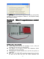
Section III
sensor
Temperature and humidity
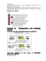
1.3.1 The connection schematic diagram is as follows:
1.3.2 The application
synchronous system
◆ Switch setting
of
the
41
sensor
in
DBT-Q2007
They are non-humidity sensor head 11111001; humidity sensor
head: 01111001.
The seventh and eighth switches are the selection of the
response speed: “00” is 0.5S, “01” is 1S, “10” is 10S and “11” is
60S.
◆ Serial connection method: One head is DBT-Q9 male head
and the other is DBT-Q9 female head, 2-2, 3-3, 5-5.
◆ Software setting: Tick the data collecting in “XMPLAYER”
parameter setting and come into [set] to tick the brightness
automatic adjustment after selecting the correct connection serial,
then click send at the right side of the set. The function can be
realized after finishing sending and exiting the software to the
playing window.
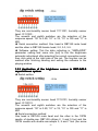
1.3.3 Application of the brightness sensor in DBT-QA9.0
asynchronous system
◆ Switch setting
They are non-humidity sensor head 11110101; humidity sensor
head: 01110101.
The seventh and eighth switches are the selection of the
response speed: “00” is 0.5S, “01” is 1S, “10” is 10S and “11” is
60S.
◆ Serial connection method
One head is DBT-Q9 male head and the other is the 10PIN
needle of double-row. DBT-Q9 utilizes 2, 3 and 5 foot and the
10PIN needle with double-row adopts 5, 6 and 7 foot (the arrow
42
place of the needle with double-row is the tenth foot), 7-3, 6-2,
5-5.
� Software setting
Tick the data collecting in “XMPLAYER” parameter setting and
tick the brightness automatic adjustment and then confirm after
coming into [set] to select the correct serial, then click send at the
right side of the set. The function can be realized after finishing
sending and exiting the software to the playing window. The
program sheet of the sensor display is added when
manufacturing the program and the brightness automatic
adjustment [Yes] is selected at the right side of the materials.
Decisions shall also be made as whether the temperature and
humidity are displayed and then the program is sent to ARM9 to
realize the function.
Note:
Other program window can not overlap the brightness
display window and the selection between the first layer and
second layer shall be separated.
1.3.4 The application of the brightness sensor in DBA-7.0
asynchronous system
◆ Switch setting
◆ 1-8 are:
[Non-humidity sensor head] 11110001
[Humidity sensor head] 01110001
Note:
The seventh and eighth switches are the selection of the
” is 10S and
response speed: “00
00”” is 0.5S, “01
01”” is 1S, “10
10”
“11
11”” is 60S.
◆ Serial connection method: One head is DBT-Q9 male head
and the other is DBT-Q9 female head, 2-2, 3-3, 5-5.
43
◆ Software setting: Only the brightness automatic induction is
entailed and the software setting is not necessary. If the
temperature and humidity need displaying, it needs: select the
temperature and humidity in the overall customized information of
the ARM6.0 software and the function needed can be realized by
sending again.
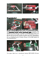
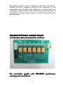
Section IV Power control board
1.4.1 Graphic of the real material is as follows:
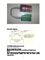
The connection graphic with DBT-Q2007 synchronous
receiving card is as follows:
44
Schematic diagram:
1.4.2 2009 multifunctional board
◆ Function introduction:
[Power automatic control]
[Control of the temperature, humidity and brightness]
Note:
The functional board R24 and R25 weld 1k resistance, single
chip microcomputer PIN25 and PIN 26 short circuit
respectively.
45
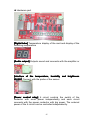
◆ Hardware part
[Digital tube] Temperature display of the card and display of the
collecting temperature
[Audio output] Outputs sound and connects with the amplifier or
sound box.
[Interface of the temperature, humidity and brightness
sensor] Connect with the probe of the sensor
[Power control relay] 6 circuit controls the switch of the
contactor with small power independently and each circuit
connects with the power contactor with big power. The external
power of the 6 circuit can be controlled independently.
46
○ The connection diagram of the hardware is as the following
figure
Note:
220V is the coil voltage of the AC contactor (AC contactor
has explained for this)
[Probe of the temperature, humidity and brightness sensor]
1,
The figure above is the interface of the functional card while the
47
figure below is the sensor of the brightness and temperature.
(Powering up is effective after connecting with the sensor).
○ Pressing line method of the probe of the sensor
I. Only RJ45 pressing line method of the temperature and
brightness is possessed.
MATE functional board:
(1) White orange (2) orange (3) white blue (4) blue (5) white
green (6) green (7) white brown (8) brown
Sensor head [SENSERout1.1]:
(1) White orange (2) orange (3) white green (4) blue (5) white
blue (6) green (7) white brown (8) brown
Note:
Not supporting SHT1X humidity
II. RJ45 pressing line method of the temperature, humidity and
brightness
MATE functional board:
(1) White green (2) orange (3) white blue (4) blue (5) white
orange (6) green (7) white brown (8) brown
Sensor head [SENSERout1.1]:
(1) White orange (2) orange (3) white green (4) blue (5) white
blue (6) green (7) white brown (8) brown
Note:
Not supporting DSI8B20
◆ Software part
[Switch control]
Select [Power management] and click [Switch control]
Click the corresponding power switch button according to the
application need and click [Ok]
[Schedule]
Click [Timely order]
48
There controller owns 6 groups of switches that can be used.
Click [Connect] and [Disconnect] icons to realize [Enter] of the
switch power. Meter screen between the appointed orders can be
established for automatic power switch according to the schedule
automatically.
49
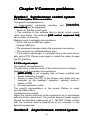
Chapter II Asynchronous control
System
Section I DBA-9.0 asynchronous control
system
2.1.1 summarize
The Led display screen has the functions of playing all kinds
of characters, symbols, graphics and videos. It has the characters
of simple control, easy operation and has been applied widely in
the society.
Led control system is the core component of the led screen.
It can be divided into synchronous and asynchronous control
systems according to the control mode. Asynchronous control
systems win the favor of the users.because of their simple
structure and high performance-price ratio. The principle of the
asychronous system is to place the image information which
edited by the computer into the frame memory of the led display
screen.
The asynchonous embedded led control system (briefly called
embedded controller) is as the asynchronous control system by
definition. It has the characteristics of the asynchronous control
system of woking offline and high performance-price ratio. It also
has the characteristcs of the synchronous control system of
control level with grey scale.
2.1.2 Function characteristics
1)completely
completely function, high expansibility
(1
The system has complete design and high expansibility,
which offer good technical support and application
development platform to clients.
It has the characterictic of further development and can
offer different solutions according to the needs of clients.
2)stable
stable performance, easy operation
(2
The system uses CPLD(Complex Programmable Logic
Device),which has unique design, rigorous structure and stable
performance.
3)high
high frame frequency, steady image
(3
The system has high scan rate. The frame rate is higher
than 120Hz within the limit of controlling area. The image has
50
good stability and is free of flicker;
4)operation
operation offline
(4
offline operation can be achieved as soon as the data has
been sent, the data will not be lost when the power is cut off.
5)good
good compatibility
(5
The system has feature of good currency, be used to
cooperate with various types of LED display units.
6)hardware
hardware architecture
(6
The hardware adopt the embedded system technique,
which realizes the network transmission and remain the serial
port communication mode.
7)software
software
(7
The interface of the software is friendly and the operation is
simple
8)maximum
maximum size of the screen
(8
full color Maximum pixels can be 320 ×192,and 16384 ×
16384 ×16384 level gray scale;
9)long
long distance transmission
(9
It adopt the advanced data transmission techniques, use
internet high-speed data conmmunication drivers, which is
antistatic and against thunder strike, supporting long distance
transmission.
10
ethernet data transmission
(10
10)ethernet
Support TCP / IP network protocol, RJ45 connecting port
corresponds to IEEE8023 10BASE_T;
11
Support a variety of content display formats
(11
11)Support
Support editing and browsing of BMP, EMF, WMF, JPG,
JPEG, DIB image formats;
Support the text (*. txt) editing and browsing;
Support the animation in the GIF format and video editing
and browsing in AVI, MPG formats
12
big capacity
(12
12)big
Support using high-capacity disks, CF cards, SD cards as
the storage medium to display different contents continuously
for several hours;
13
data clock
(13
13)data
Support the digital clock display, support real-time
correcting time, the clock's position and font color can be set by
the software, the clock just show hours ,minutes and seconds.
The display format is XX:XX:XX;
14
Multi-zone display
(14
14)Multi-zone
51
LED display screen is divided into three regions ,there are
the main region, clock region and moving subtitle region;
15
various stunts
(15
15)various
Stunts can be done alone in each image. It supports entry
and exit ways. One image can be used repeatedly. Moving
speed, stopping time, repetition and subtitle can be set in each
image. It supports mosaic, horizontal bars, vertical bars,
vertical blinds, horizontal blinds, 360 degrees left rotation, 180
degrees left rotation, 90 degrees left rotation, 360 degrees right
rotation, 180 degrees right rotation, 90 degrees right rotation,
middle to around, around to middle, cross from center, cross
from around 36 stunts, etc.
16
moving subtitles, static subtitles
(16
16)moving
The colors, fonts, and sizes of the subtitles can be set, the
static subtitles have ten lines at the most.
Support real-time input and the editing and browsing of the
text(*.txt);
99 moving subtitles can be set independently, and any
subtitle can be invoked when needed.
There are two display modes: transparent display and
overlay display. When it is transparent display, the subtitles
play on the background image. When it is overlay display, the
image is covered by the background color, the background
color of the moving subtitles can be selected.
Position、stopping time、moving speed and cycles of the
moving subtitles also can be set.
Note: the moving mode of the subtitle only supports moving
from right to left at present.
17
brightness adjustment
(17
17)brightness
Support adjustment of multiple levels of brightness, the
brightness can be set by the software or by our ARM accessory
board(support the temperature, humidity and light sensor)
18
temperature and humidity display
(18
18)temperature
Support temperature and humidity display (only support our
company’s temperature and humidity sensor accessory board).
It is displayed on the top line in the screen( the location can be
customized );
19
hardware lock-screen display
(19
19)hardware
Support the standard digital keypad connectors. realize the
control of lock screen of the hardware;
20
others
(20
20)others
The specifications and sizes of the display screen can be
52
adjusted in the embedded controller series products.
Embedded controllers support the indoor screens and
outdoor screens. Scan mode: full color 16 scans, full color 8
scans, full color 4 scans, full color 2 scans, full color static
state.
The centralized control of network of several computers can
be achieved by setting different IP address.
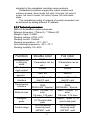
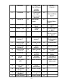
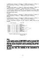
2.1.3 Technical parameters
DBA-9.0 Embedded system parameter
External dimension: 176mm (L) * 109mm (W)
Weight of card: 0.25KG
Working voltage: 4.75V~5.2V
Working current: 1500mA
Working temperature: -10℃~50 ℃
Limit working temperature: -20℃~70 ℃
Working humidity: 5%~95%
Function
Double color
Full color
Red/green/blu
e and gray
scale
The highest
clock output
Storage
amount
Memory
interface
4 ---65536 level
(Parameters can be
set)
4 ---65536 level
(Parameters can be
set)
25MHZ
25MHZ
Max: 4G
Max:4G
Transmission
interface
Mode of scan
Intelligent
guide
Control range
Support SD card/U
Support SD card/U
disk/CF card
disk/CF card
Standard network
Standard network
RJ45
RJ45
RS232/485(Special) RS232/485(Special)
Static, 1/2 scan, 1/4
Static, 1/2/scan, 1/4
scan,
scan,
1/8 scan, 1/16 scan
1/8 scan, 1/16 scan
Support within
Support within 16*16
16*16 points data
points data path
path
320*240(without
320*240(without
receiving card)
receiving card)
640*480(with
640*480(with
53
receiving card )
Output
interface
Support video
Brightness
sensor
Multi window
Temperature
and humidity
sensor
Sound output
receiving card )
Supported standard
Supported standard
HUB(16 group RGB) HUB(16 group RGB)
Support special 24
Support special 24
group RGB
group RGB
MPG / MPEG / AVI /
MPG / MPEG / AVI /
ASF…
ASF…
Support
Support
Support
Support
Support
Support
Support
Support
2.1.4 Issue list
1) DBA-9.0 embedded full color control system 1pcs
2) < technical support manual of led control system> 1pcs
3) led display control software CD 1pcs
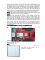
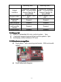
2.1.5 Hardware recognition
� Front photo(with receiving card mode,With net mouth
output)
�
Front schematic diagram
54
[SW1] reset button.
[CON8] power connection base, 5V connects with + 5V power
and GND connect with the ground.
[CON5] this is the power socket, among which 1 connects with +
5V power and. 2 、 3 connects with the ground and 4 foot is no
connection.
[LED5] This is the power indicator and it will be in red color after
electrifying.
[LED1 and LED8] This is the signal indicator and it means the
main control card work ing when the two lamps are bright.
[CON9] Is the standard RJ45 signal port and connects with the
network port by means of the five-category net wire. As for the
pressure method of the net wires which connects with the
computer and information point, please refer to the appendix.
[J7, J8 and J9] These are the data outputs ; J7 and J8 are the
socket of the flat cable of 50pin and the 50pin flat line is used to
connect with the interface board of the different screens on the
market. Each 50pin flat cable outputs 8 data lines. J9 is the
special kind of our company and it is used to additionally increase
8 data lines (that means there are 24 output signals on the whole
board which can connect with different screens by means of the
interface board of our company. J8 is the first output of scan and
the corresponding between grounds shall be noticed. Additionally,
one end with double-arrow mark is the first stitch;
[OE] Is the polarity switch of the enabling (OE) and it shall be set
on the on or off status according to the display screen.
[CON6] COM port used for connecting with other equipment such
as the brightness sensor, temperature and humidity sensor of our
company.
[CON14] This is the socket of the CF card and the mainstream
55
CF card on the current market.
[CON7 and CON7A] This is the USB interface and the
mainstream U disk on the current market.
Note:
U disk with different specifications and brands is not
” brand.
supported and we suggest adopting the “KINGSTON
KINGSTON”
[CON3] Standard audio output
◆ Back schematic diagram
[CON2] This is the standard socket of the SD card which inserts
the mainstream SD card on the market.
[CON1] Inserts the core board equipped by our company.
Note:
Since the density of the socket is relatively high, please
never insert or unplug the core board casually.
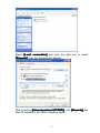
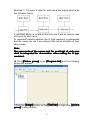
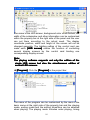
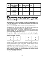
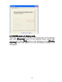
2.1.6 Introduction of the application method
◆ Setting of the computer IP: Right click the network
neighborhood and the local connection will appear by clicking
property, as the following figure:
56
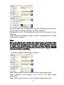
Select [Local connection] and click the right key to select
[Property]
[Property], then the following will appear:
After selecting [Internet protocol (TCP/IP)]
(TCP/IP)], click [Property], the
fixed IP address is set as the following figure:
57
Note:
I. IP address must not be in conflict with that of ARM 9 due to
the adoption of the same address.
II
II.. IP address of the computer must be set within the same
[section] with ARM9 which is defaulted as “1” section.
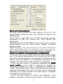
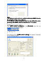
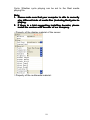
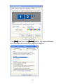
◆ DBA-9.0 parameter setting
Click [LED control configure] in the [Control] menu bar, as
illustrated in the following figure:
The dialogue box of [LED control setting] will appear, illustrated
as the following figure:
58
Click [Wizard] button on the lower right side and the following
figure will appear:
Click [Ok]
[Ok], DBA-9.0 will restart automatically (Reset) and the
[Wizard] will be operated again after the restart of the DBA-9.0 is
finished until the following figure appears:
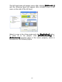
The following figure will appear by click [Ok]
[Ok]:
Set according to the minimum module group of your screen and
with rows which are brought by one group of data. Suppose the
59
minimum module group is 16*16 and there are two groups of
RBG signals being controlled, it will be set as 16*8. If there are
four groups of RGB signals being controlled, it will be set as 16*4,
click enter key when finishing setting, as the following figure:
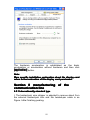
Fill in the dialogue box above according to the rows that are or
are not lighted and click [Ok] after finishing, and then the
following figure will appear:
There shall be one lamp being bright or flashing on the LED
screen at this time and find the corresponding position in the grid
figure above according to the position of the lamp on the screen.
There will be another lamp being bright on the screen to guide
you to click it after clicking and keep clicking until there is not grid
to be clicked. Press [Ok] and the following will appear:
60
Click the corresponding unit row one by one by means of the
mouse according to the order of the illumination line on the
display screen. Click [Ok] after finishing and the following figure
will appear:
Click the corresponding unit row one by one by means of the
mouse according to the order of the illumination line on the
display screen. Click [Ok] after finishing and the software will pop
out the following hint:
Select [Yes (Y0) or [No (N)] according to what the actual LED
61
display screen indicates and the following hint will appear after
selection:
After clicking [Enter], adjust the following different kinds of
parameters according to the actual situation, as the following
figure:
Click sending after finishing adjustment and reset is carried out
again after DBA-9.0 saves the parameter. The software will exit,
as the following figure:
DBA-9.0 parameter setting is hereof finished.
◆ Manufacturing and sending of the program
Return to the playing interface after exiting setting, illustrated as
62
the following figure:
Then click [New] and the following figure will appear:
Select [ARM9 special program list]
Click [Ok] after confirming the size of the screen and you will see
the following figure:
63
Set according to your need and select the single or multiple
windows. Suppose we select forth window to edit, click
arrangement distribution (2*2) and the following figure will
appear:
You start to adjust your window and set the window you need.
What you need to pay attention to is that the windows within the
same panel are not allowed to overlap, or it will be issued wrongly.
Then add the program you need in each window and you can
click start menu to preview the next effect after finishing adding,
64
illustrated as the following figure:
Under the circumstance that no problems are possessed, the
program can be directly sent to DBA-9.0 and select [Send to
AMR9…] in the control menu, as the figure below:
The software is able to switch the program automatically. Select
the DBA-9.0 IP to be sent and click [Send] after finishing
switching the files. (The software is able to support 254 DBA-9.0
to the utmost to send program at the same time for each time), as
the following figure:
The following figure will appear to select the storage media after
clicking [Send]
[Send]:
65
Click [Enter] after selecting the type of the memory card and the
software will send the program to DBA-9.0. The program hereby
has finished sending.
Section II
system
DBA-7.0 asynchronous control
2.2.1 Hardware recognition
2.2.2 Function characteristic
◆ Each image can set the roll message or not, or the roll
message can be set on an interval basis.
� The display of 36 kinds of stunts and clearance stunts
respectively can be supported.
� The playing of unicolor, double color and full color picture is
supported.
� BMP, JPG, ICO, DIB, EMF and other kinds of picture formats
as well as the files and GIF, AVI, MPG animation are
66
�
�
�
supported.
Text editing is supported.
The interface of the software is in simple and convenient
operation.
Timely playing can be realized.
The external interface is supported such as temperature,
humidity, clock etc.
2.2.3 Software introduction and application explanation
Firstly, select the installation package according to the matched
optical disk and then click it to install according to the defaulted
hint until successful installation appears. The desktop will appear
after successful installation
Double click the icon and the main interface of the software
operation will appear as the following figure:
It can be divided into: Menu bar, tool bar, program list, edition
area and status bar according to the function area.
2.2.3.1 Software introduction
[Menu bar]
67
File, editor, remote, options and help are included.
[Tool bar]
They are new, open, save, send, exit, program, image, Picture
Movie Multext T Roll Msg copy, paste, cut, and delete
respectively.
[Status bar]
A very useful status hint bar is situated in different editing
statuses and displays the corresponding information.
[File] menu contains six menu items illustrated in the following
figure.
New establish: it is used to establish a new LED program list
Open: it is used to open the LED program list which has been
edited previously.
Close all: it is used to close and delete the LED program list.
Save: It is used to save the current LED program list.
Saved as: It is used to save the current LED program list in other
files.
[Additional function] Menu contains the following eight menu
items
2.2.3.2 Software application
◆ Click [New]
[New], which means establish new program list, and then
the following picture will appear:
68
◆ Click [Control card] in the [program list] and the following
figure will appear.
◆ Click [Base parameters] to carry out the setting of the basic
parameter
[Name of the card] Is the name of the LED big screen, and the
defaulted value can be saved or edited according to the actual
69
situation.
[TCP/IP address] Is the TCP/IP address of DBA-7.0 control
system.
[Size] Is used to establish the length, height and color of the LED
big screen, and the parameter list is as follows:
Dimensions
Full color
Double
Single color
parameters
color
≤512
No
Length
( Pixel ≤256
point)
≤256
No
Height
( Pixel ≤128
point)
◆ Click [Advanced 1] to carry out the setting of the senior
parameter
[OE signal] Is the polarity of OE, [Negative] means OE is low
(This is 0) and effective, [Positive] means OE is high (That is 1)
and effective.
[Driver] The instant current source is the effective illumination
when the data is 1 (such as TB62726) and the rest is the effective
illumination when the data is 0
[Color group] The color order when it is under the full color.
[Clock data clock duty cycle] has not been open to the user at
present and it is the data clock duty cycle with 25% defaulted
value.
[Gray scale] The gray selection of the screen can support 4,096
grade gray which is at the most for the full color screen and the
double color screen. The users can set it according to their own
70
needs.
[Line-close time] The selection of the de-shadow effect means
the de-shadow pulse width and the user can set it according to
their own needs.
[Clock frequency] Means the frequency of the data clock
frequency and the users can set it according to their own needs.
[Effective scan] Means the position of the first line of data of the
scan screen and the users can set it according to the actual
situation.
[Scan mode] Is the scan mode of the screen and the users can
set it according to the actual situation.
[Brightness grade] Means the brightness of the screen and the
users can set it according to their own needs.
[Line height] Means the one in each area, which is illustrated in
the following example:
Example 1: 1/8 scan, 16 rows for each area. The signal trend is
as the following figure:
The parameter is hereby set as: the scan mode is eight scan,
post high/each group of data selects 16 rows, Z reentrant selects
eight lines of reentrants.
◆ Click [advanced2]] To carry out setting of senior parameter 2.
71
[Row inverse parameters] Means the direction where the data is
driven and it is the normal method when driving from upper to
lower and vice versa, then the row order needs adjusting. How
many reverse will be selected is subject to the post high and scan
mode of each area. 2 row reserves mean the mutual reverse
while 4 row reserves means the reverse of every two rows
following with the other rows. The following are the two examples:
Example 1: 1/8 scan, 16 rows for each area. The signal trend is
as the following figure:
The parameter is hereby set as: The scan mode is 8 scan, post
high/each group of data selects 16 rows and the adjustment of
the row order selects 16 row reverses. Z reentrant selects eight
lines of reentrants.
Example 2: 1/4 scan, 16 rows for each area. The signal trend is
72
as the following figure:
The parameter is hereby set as: the scan mode is four scan, post
high/each group of data selects 16 rows and the adjustment of
the row order selects 16 row reverses and 8 row reverses. Z
reentrant selects eight lines of reentrants.
[Column inverse parameters] Means the order of each bit. 2
line reverses means the mutual reverse in two lines while 4 line
reverses means the mutual reverse of every two digits one after
another. For an 8-digit data as an example, the order of its screen
is 7-0, the order will be adjusted as: 2 line reverses, 4 line
reverses and 8 line reverses. The realization process is as
follows:
First with 8 line reverses, the order will be changed into: 3 2 1 0 7
654
Following with 4 line reverses, the order will be changed into: 1 0
325476
Following with 2 line reverses, the order will be changed into: 0 1
234567
[Row or column return] and [Standard reentrant] are the
direction of the data transfer. If one row transfers to the bottom, it
would be one row reverse while if there are two, it will be 2 row
reverses when returning and so on. The user can set it according
to the actual situation of his/her own screen. The example refers
to 1 and 2 of the senior parameter 2.
Note:
The scan mode of the screen and the post high of each area
shall be integrated for observation when setting the
reentrant value.
73
Example 1: 1/4 scan, 4 rows for each area, the signal trend is as
the following figure:
Z reentrant option is invalid at this time and it will be valid in case
of 8 rows for each area.
[U reentrant] selects whether the U type reentrant is possessed
and the users can set it according to the actual situation of their
own screen.
Note:
The scan mode of the screen and the post high of each area
shall be integrated for observation when setting the U type
reentrant.
◆ Click [Picture group] in the [Program list] and the following
picture will appear:
○ Click the [Image] button on the [Tool bar] or right click [picture
group] to add pictures.
74
The same method can be applied to adding animation file (Gif,
mpg and avi) and files with text format. Only by selecting the file
path in the editing area of the picture setting on the right side, can
the modification be carried out.
○ After selecting the file, edit the property (Enter the stunt, exit the
stunt, moving speed, stay time and cycle times etc.)
The stunt table is as follows:
[Stay time] means the interval time from finishing displaying
when entering the stunt to just exiting the stunt.
◆ Click [Roll message
message]] in the [Program list] and the following
75
picture will appear.
○ Click [Roll message] button in the [Tool bar] or right click
[Picture group] to establish new roll message.
[Font] Is used to set the font of editor text area
[Size] Size for the font, there are 12、16、20、24、32、40、48、
64、72 etc.
76
[Color] Establishes the color of the text font.
[Background color] Establishes the background color of the
text.
[line] is defaulted as being standard, which means 0 point row
spacing.
[Overall pages] The number of the pages of the output text,
which means carrying out cutting according to the screen size
(such as 128* 96)
[Current page] Is used to browse the display situation of each
page.
[Size of the picture] Is used to set the length and width of the
screen.
[Open] Button is used to open the files which have been edited
before.
[Save as] button produced the files of imf, rol, BMP etc.
according to the need.
[Close] Button is used to close the dialogue box.
[Display mode] There are transparent display and covered
display. When it is under transparent display, the roll message will
display transparently without background color which can not be
established. When it is under the covered display, the background
color can be established.
[Background color] Establishes the background color of the roll
message and setting can not be carried out when the display
77
mode is under transparent display.
[Width] The length of the screen is set automatically.
[Height] Is fixed as 16.
[X coordinate
coordinate]] Is fixed as 0.
[Y coordinate
coordinate]] Dereferencing scope as: 0~ ( height of screen
body -16).
[Dwell time
time]] Dereferencing 0-65535, value the larger and the
lower.
[Movement speed] Dereferencing 0-65535,value the larger and
the lower.
[Cycle index
index]] Dereferencing 0-65535.
Note:
The roll message is the global program and no matter how
s are possessed, each screen will display
many roll message
messages
on an overall basis by selecting the send property.
◆ Flow of the clock, temperature and humidity manufacturing
Click [Global customization information] in the [Program list]
and
will display the following picture:
◆ How to play the programs regularly (Only 10 programs can be
played regularly at present)
Click [Program 1] in the [Program list]
and the
following picture will appear:
78
The time limit is edited according to the actual situation.
◆ New version ARM7-E
The difference between the new version ARM7-E and ARM7: it is
identical on the perspective of the hardware while the difference
lies in the software, as the following figure:
○ The new version ARM7-E has added the intelligence of the
parameter setting, that is “intelligent setting" the process of which
is the same with that of DBA-9.0(ARM9).
○ The parameter setting of the new version ARM7-E separates
79
with the program sending independently to avoid the previous
constraints of sending the parameter together with program. The
abnormal display of the screen will be caused when sending the
program under the circumstances of not knowing the parameter.
Section III Video processor
2.3.1 Points for attention for safety
Danger!
There is high voltage within the machine and the
non-professionals are not allowed to open the machine cover to
avoid danger.
Warning!
1. The equipment is not allowed to be splashed by water drop or
water, and place the articles with liquid.
2. The equipment is prohibited to get access to the fire in order
to avoid fire.
3. At least 20CM gap shall be left around the equipment for the
purpose of adequate ventilation.
4. If the equipment produces serious noises, fume or peculiar
smell, the socket shall be pulled out immediately and contact
with the supplier;
5. It is prohibited to pull in and out of HDMI/DVI signal cable with
electricity.
Attention!
1. Please read the instruction carefully before suing and take
care of it for back up;
2. Please pull out of the socket of the power under the
circumstances with lightening or without use for a long time;
3. The product is not suitable for the operation and debugging
by the non-professionals and the user needs the guidance of
the professionals;
4. Never stuff any materials to the via hole of the equipment to
avoid damage of the equipment or electric shock;
5. It is not suitable to locate the equipment near water or other
humidity place;
6. It is not suitable to place the equipment on the fin or other
place with high temperature for application;
7. Under the circumstances of using HDMI cable, one section of
wire from the HDMI port is not allowed to suffer from the
external force.
8. The socket of the power shall be pulled out of and someone
shall be entrusted for repair in any of the following cases:
○ When there is liquid splashing into the equipment;
80
○ When the equipment falls down or the crate is damaged;
○When the equipment occurs something abnormal or the
performance changes;
9.
There is no components to be repaired within the video
processor and please do not
open the crate and we are
not responsible for the results by opening the crate arbitrarily.
10. Please keep certain distance with other equipment to facilitate
operation and ventilation.
11. Please never pull in and out of different signal wires with
electricity in any of the situations.
2.3.2 Hardware connection
1. The signal port graphic of the back panel:
2. Port explanation
◆Signal input
DBT-Q09 video processor supports the input of six kinds of signal
sources, among which:
[HDMI1] the digital signal input of 1 circuit computer (PC)
[HDMI2] high-definition digital signal input of 1 circuit
[VGA] analog signal input of one circuit computer
[YPB/PR] high-definition component video input of one circuit
[CVBS] PAL/NTSC compound video input of one circuit
[S-Video] PAL/NTSC system bright color separate video input of
one circuit
◆ Signal output
[HDMI] The digital signal of one circuit computer connects with
the display equipment with DVI digital interface.
[VGA] The analog signal of one circuit computer connects with
the display equipment with VGA interface.
[1, 2, 3, 4, and RJ45 interface] The function of 1 and 2 ports
shall refer to HVT-07; 1 and 3 ports display the same content
while 2 and 4 ports display the same content.
◆ Communication control
USB interface: Serial communication control input
2.3.3 Schematic diagram of the system connection
81
2.3.4 Explanation of the keyboard key-press:
◆ Schematic diagram of the front panel:
Key-press explanation:
◆Key-press
○ Shift key:
shift
Key-press status switch: there are three key-press statuses in this
equipment and they are: the first function, the second function
and the third function respectively. Shift is used for the switch
among the functions and it is defaulted as the first function when
starting up. Three red lamps correspond with the instruction of the
first, second and third function from top to the bottom.
Under the mode of the first function:
1.Selection key of inputting the video source
Key
82
Selection of the video source:
DVI-A: selects the HDMI1 (PC) signal input
DVI-B: selects the high-definition digital signal input
VGA: selects the analog signal input of the computer
S: selects PAL/NTSC system bright color separate video input
Yp: selects high-definition component video input
AV: selects the analog signal input of the computer
Note 1:
The selection of the major and minor window sources:
Two association groups of the picture-in-picture mode are as
the figure above. If one input source in the association group
1 is selected, it will be deemed as the major window while the
association group 2 will be the minor window for the last
choice. Similarly, the selected source is in the association
group 2, the input source will be the major window and
association group 1 will be selected as the minor window in
the last choice. There are altogether 18 kinds of such
combinations of the major and minor windows the signal of
which cannot select two signals in the same association
group at the same time.
2. Up and down key:
Key
They are used as the brightness adjustment of the major
window.
DOWN: reduce (Decrease) the brightness value of the major
window.
UP: increase the brightness value of the major window
Note 2:
The adjustment scope of the brightness is: 0-99 grade and
the continuous adjustment can be carried out by pressing
constant value.
3. Parameter key of the image display:
83
Key
S1: S1 owns two kinds of functions and Function a occurs when
pressing for once while Function b comes out when pressing for
the second time and they are:
a) Full screen display of the major window
b) The size of the system window recovers to the user-defined
mode of the user
S2: S2 owns two kinds of functions and Function a occurs when
pressing for once while Function b comes out when pressing for
the second time and they are:
a) Picture locking of the major window
b) Locking rescission of the major window picture
S3: S3 owns two kinds of functions and Function a occurs when
pressing for once while Function b comes out when pressing for
the second time and they are:
a) Picture FILL of the major window picture, that is: the major
window picture fills with the area of the major window size
b) Picture FILL of the minor window, that is: the minor window
fills with the area of the minor window size
S4: S4 owns two kinds of functions and Function a occurs when
pressing for once while Function b comes out when pressing for
the second time and they are:
a) The picture of the major window 1:1 that is: the picture of the
major window displays as the actual size of the vide source
signal
b) The picture of the minor window 1:1, that is: the picture of the
minor window displays as the actual size of the vide source
signal
Under the mode of the second function:
Key
1) Brightness, chroma, saturation and contrast
DVI-A: the brightness reset of the minor window
DVI-B: the brightness reset of the major window
84
VGA: the saturation of the major window
S: chroma of the major window
Yp: the contrast of the major window
AV: not opened temporarily
DVI-B and DVI-A are the shortcut keys of restoring factory setting
of the major and minor window respectively and the factory
brightness value of the corresponding window will be recovered
by pressing the key.
Note 3:
The adjustment mode of the brightness, chroma, saturation
and contrast:
The value is increased by pressing UP key and decreased by
DOWN key after selecting VGA (Saturation of the major
window) or Yp (Chroma of the major window) or AV (Contrast
of the major window). The value can be adjusted
continuously by pressing UP or DOWN key for a long time.
Under normal circumstances, the brightness, chroma,
saturation and contrast have been adjusted to the standard
status before delivery and the following adjustment thus
becomes unnecessary.
Key
The value adjustment is carried out by the coordination of other
function keys under the appointed function. UP key can be used
for increasing and DOWN key for decreasing to carry out
adjustment when the width, length, Y coordinate of the starting
point and X coordinate of the starting point etc. are selected, for
example, Note 3.
Key
S1: S1 also owns two kinds of functions. Function a works when
pressing for once while Function b works when pressing for the
second time and they are:
a) Height selection of the major window
b) Height selection of the minor window
85
S2: S2 owns two kinds of functions. Function a works when
pressing for once while Function b works when pressing for the
second time and they are:
a) Width selection of the major window
b) Width selection of the minor window
S3: S3 owns two kinds of functions and Function a occurs when
pressing for once while Function b comes out when pressing for
the second time and they are:
a): Coordinate in Y direction selection (Starting point) of the major
window
b): Coordinate in Y direction selection (Starting point) of the minor
window
S4: S4 owns two kinds of functions and Function a occurs when
pressing for once while Function b comes out when pressing for
the second time and they are:
a): Coordinate in X direction selection (Starting point) of the major
window
b): Coordinate in X direction selection (Starting point) of the minor
window
Under the second status, after being selected, S1, S2, S3 and S4
can coordinate with UP key and DOWN key to change its
corresponding value respectively for the purpose of changing the
coordinate of the screen size. The width of the two windows in the
equipment can not surpass 1, 024 at the same time with 1, 280*1,
024 display input resolution.
Under the status of the third function:
S1: recovers the restore factory setting of the key-press board
and 4*4 matrix red lamp will flash for 7 times and the reset is
finished by pressing S1 key for more than 10 seconds. The
system needs powering up after resetting the system.
S2: recovers the reset of the video system.
Note:
When the adjustment data is lost or in disorder for the
reasons unknown, resulting in the failure to normally display
the image of the system, you can recover the data when
delivery by means of initialization operation and then adjust
according to the setting explanation above.
2.3.5 Operation case
Operation case
Connect the peripheral equipment including input source (6
circuits at least connects one circuit of source and HDMI interface
86
connects the computer by opening [Copy mode],) (The case
takes computer source HDMI 1 port and AV two circuits channel
as an example), output source USB.
1. Open DBT-Q2009 power and it is defaulted as the first status
when starting up. Press HDMI1 on the panel and observe
whether there are some changes (controlled) NOT1 on the image of
the LED screen or [Output external display] and press S3 key for
twice.
2. Press [SHIFT] key for once to come into [Status of the
second function] (the small liquid crystal display on the right can
be seen or the second lamp of the red lamp indication will be
bright)
� Press the liquid crystal on the right side of S3 [Y starting point
of the major window] and there will be Y value displayed. “UP”
can be used for increasing the value of the coordinate while
[DOWN] key for decreasing the value of the coordinate with the
defaulted value “0”.
� Press S3 [Y starting point of the minor window] again, the Y
starting point of the minor window is adjusted by the coordination
of “UP” and “DOWN” key.
Similarly, S1, S2 or S4 coordinate with “UP” and “DOWN” key to
adjust the size and coordinate of the corresponding windows
respectively; press “DVI-A” or “DVI-B” or “VGA”, “S” or “YP” or
“UP” and “DOWN” key can also be used to adjust the setting of
the contrast, saturation and other parameters of the
corresponding major window. (The specific function under the
second status refers to the function explanation of “under the
mode of the second function”)
1. [SHIFT] Key is used to enter “the first function mode” and
press S3, “FILL” S4
“1:1” for adjustment. Pressing once means
the major window while the minor window will come out by
pressing for the second time.
2. The switch of HDMI1 and AV between the major and minor
windows can be conducted by finishing the 3 procedures above.
The major window will display the content of AV by pressing AV
while the minor window displays the content of HDMI1. When
pressing the HDMI1 content that the HDMI1 major window
displays, the minor window will display the content of AV. In this
way, the switch of 2 circuit source can be realized. If there is the
switch of the source of more circuit, we only need to select the
corresponding channel first and then adopt S3 and S4 to set the
corresponding channel as “FILL” or “1:1”. When we setting the
parameter of the “corresponding channel”, there must have video
87
input on that (the content of the channel shall be output), only in
this way, can the parameter issued respond.
3.
NOTE: If the output external display is connected, we can
make a judgment on whether the equipment is under control
by observing whether the content of the display has changed
or not. If the external display is not connected, we can carry
out judgment by means of LED electronic screen.
a. Black screen of the electronic screen
1. Under the normal circumstances, the output yellow lamp of
RJ45 port of the receiving card is connected, the green lamp will
be bright always. On condition that the yellow is bright while the
green one is not, it means that the receiving card has been
connected with the lack of data, please confirm the connection of
the video source and HDMI needs to open the copy mode.
2. The data flash of the receiving card is still in black screen and
inspect whether the parameter of the receiving card is correct; the
too small screen displays that the position coordinate has
deviated and inspect whether the resolution of the display card is
1, 280*1, 024 or not. Or press S3 under the mode of the first
function and press S1 to see whether there has displayed or not.
The setting and adjustment can be carried out by the coordination
of the software according to the explanation when there is
display.
3. Inspect whether the source channel is selected correctly and
whether what has been played is DVD. Some videos own the
black edge on the upper and lower side.
4. Please contact with us if there is still something unclear.
b. The picture of the window is not clear
Please inspect the resolution of the computer and 1, 028* 1, 024
mode is entailed.
88
Chapter III Multimedia program
and playing
Section I: Summarize
3.1.1 Function characteristic
Designed by the professional working group of LED studio device,
XMPLAYER LED studio device is a set of device specially
designed for the program manufacturing, playing software and
supporting files of many format: text file, WORD file, all the picture
file (BMP/JPG/GIF/PCX...) and all the animation files (MPG /
MPEG / MPV / MPA / AVI / VCD / SWF/ RM / RA / RMJ /
ASF...)with the characteristic of the strong function, convenient
application and being easy to learn.
3.1.2 Operating environment
Operating system
Chinese and English Windows98/me/2000/NT/XP
Hardware configuration
CPU: Pentium above 300MHz
Memory: 64M
Video card: Standard above VGA 256 display mode
Related software
Windows Media Player from Microsoft (MediaPlayer) -- must be
installed
OFFICE2000-- If necessary, the WORD file must be installed
RealPlayer---Installation is entailed when Realplayer file needs
playing
Section II Installation and unloading
3.2.1 Installation
The software installation of XMPLAYER LED studio device is
easy and the operation is as follows: insert the installation optical
disk of the LED studio device to the CD-ROM of the computer
and the catalogue the optical disk locates in will pop out
immediately (if it does not pop out, double click the optical disk
after selecting), illustrated as Figure 2-1.
89
(Figure 2-1)
The selectable installation guidance will appear after double
clicking [Autorun. exe]
[XMPLAYWE] is required.
After selecting [Xmplayer] item, click the installation button on
the lower right side and the following figure will appear after that:
If only Chinese and English are needed to install, installation can
be carried out after selecting [English] or [Chinese]
[Chinese]. If you
intend to change the installation catalogue or other languages,
select
button and the following procedure will appear:
Firstly: select the installation path
90
Secondly: Select the language category
Thirdly: Select the installation button
91
It is defaulted as installation when the following interface appears
during the installation process and operation according to the
following procedure. Please confirm the operation when
defaulting on an overall basis.
92
93
After the successful window
will appear, the icon
and start->
procedure ->DBstar, then the following icon will appear
The procedure can be
operated by operating xmplayer icon.
3.2.2 Unloading
XMPLAYER LED studio device software offers the unloading
function to allow you delete all the files, procedure group and
shortcut of XMPLAYER LED studio device on a convenient basis.
The user can click [Start ->procedure ->DBT-Qstar->UnInstall,
the LED studio device will be unloaded] (Method 1 figure). Select
[Add/delete procedure] in the [Control panel] for fast unloading.
Unloading (Method 2 figure), all the files, procedure group and
shortcuts can be unloaded by selecting automatic option at this
time.
Figure of Method 1:
94
95
Figure of Method 2:
Section III
application
Specific explanation for
3.3.1 Program composition
One program is composed of several subprograms which
contains many program windows and these windows are used to
display the text, picture, animation, segment of the multimedia
and other contents that the user intends to play and they include:
text, editable text, table, clock, analog clock, website page,
sensor, Word and Excel files etc.
3.3.2 Introduction of the interface window
The operation interface of the XMPLAYER LED studio device
software is illustrated as Figure 3-1: there are two windows
altogether: playing window (The default will not be displayed at
the beginning of starting until new establishment0) and control
window (Figure 3-2).
96
Figure 3-1
Figure 3-2
97
◆ Playing window
The playing window (This is the content displayed on LED screen)
is used to display the text, picture, animation, and segment of the
multimedia and other content that the user intends to play. The
content here is synchronous with that displayed on the LED
screen and the software supports multiple playing windows.
◆ Control window
The control window is used to control the place and size of the
playing area as well as the content to be played and it can be
expanded into edition window. It also contains menu bar, tool bar
and edition control. The control window with edition is as follows:
Menu bar: including file, edit, play, control, tool, ducument and
help the seven submenus.
Tool bar: is the fast operation of the menu function.
Edition control: is divided into two parts, the left half is the
program selection which displays the program and the
information of the subwindow while the right half is the control
option which controls the playing stunt and time etc. of the
program.
3.3.3 Function introduction
3.3.3.1 Menu bar: including file, edit, play, control, tool,
document and help
help。
98
◆ File menu, illustrated in Figure 3-3 and it contains new
establish, open, close, save, save as, save with materials, save
all, release, send the current program to FTP, language and exit.
New establish: Is used to establish a new LED playing mode
(ARM9 and ARM9V2.0 and synchronous distinction).
Open: Is used to open the files of the LED studio device which
have been edited before.
Close: Is used to close and clear the current studio files of the
player.
Save: Is used to save the current files of the LED studio device.
Save as: Is used to save the current files of the LED studio device
as the new files of LED studio device.
Save with materials: Is used to save the current files of the LED
studio device and save the materials in a materials base.
Save with materials: It is used in DBA-9.0 system. When DBA-9.0
system owns 1 server to manage and send the program and the
server is needed or the computer is reviewed to carry out the
content to be sent, the control computer will save both the
program list and materials into the review computer. After it is
confirmed by the review computer, review computer is used again
to send to DBA-9.0 system for playing. The schematic diagram of
the system is as follows:
99
Special explanation:
1. There is a sharing catalogue for each server
corresponding to the area of each set. The number of the
sharing catalogues is subject to the set number.
2. After finishing editing the content to be played, the area
computer will copy the program list and file to the catalogue
corresponding to the server.
3. After finishing reviewing, the review computer will
directly send to each display screen.
4. The area computer is only responsible for sending to the
server, which is the unidirectional communication. The
review computer and server are both bi-directional
communication.
5. At most 255 display screens can be connected in each
corresponding network section.
Save all: The manufacturing and broadcasting device supports
multiple screens and program lists at the same time. When
several LED screens are being manufactured at the same time,
press [Save all]
all], and the system will save all the work with the
format *.XMP. Meanwhile opening in the next time, several LED
screens will be opened and displayed under “program list” of the
menu bar. Issue: is used for DBA-9.0 system. When the network
is used to issue content to DBA-9.0 and if the files are quite small,
the transmission speed will be very fast. If it is in the type of the
video file, the time for sending will be relatively long. At this time,
what needs doing is to insert the storage (U disk, SD card or CF
100
card) used by the DBA-9.0 to the computer by means of the
mobile card reader and “issue” the files which has finished editing
to the storage, then insert the storage to the slot corresponding to
DBA-9.0 and normal playing thus can be carried out.
Language: It is used to select the language needed and there
are simplified Chinese, traditional Chinese, English, Japanese
and Russia at present. In the core design of the manufacturing
and broadcasting device, what we all adopt is the module design
and if the user needs certain kind of language, what they need to
do is to add the module of the language to the system. The
specific operation method refers to [Introduction of the
language modification]
modification]. The reason why the three smell
graphics in the frame is for the interface left for the users about
the module of the language.
Note:
Windows XP simplified Chinese operation system is taken as
an example. If the user intends to select traditional Chinese,
the menu bar and Chinese characters in the software will
change into clobber. If such phenomena happens, please
select [standard and format] of the [area option] panel within
[control panel] and [area and language option] as [Chinese
(Taiwan)] and select [Language of non Unicode procedure]
within [Senior] as [Chinese (Taiwan)], then press [Enter] to
restart the system. The application mode of other languages
is the same with this and during the transformation process,
if the procedure belongs to the copy version instead of the
installation version, please remove the Chinese name of
catalogue where the file stays, otherwise the system will not
recognize Chinese character, resulting in the failure to
operate the software.
Exit: it is used to exit LED manufacturing and broadcasting
device.
Note:
Please save the work you are editing before exiting and after
the software exits, the system will not save the current work
and only the choice of open or new establish is accessible
when entering the system again.
Save all: It is used to save all the current studio device files
opened by the player.
101
Language: It is used to switch language (Simplified Chinese,
traditional Chinese, English, Japanese, Korean etc. are
supported at present).
Exit: it is used to exit the LED studio device.
Canceling LED studio device: Lock LED studio device (The
mouse and keyboard can be locked).
◆ Edition menu:
Just as Figure 3-4, it contains add (insert file…, material base…,
Flash, picture, multimedia, clock, video input, digital clock,
website page and text etc.), delete, cut, copy, paste, move
forward, move backward, hide the edition content, refresh, place
(the place of the current window in the screen) and size (the
proportion that the current window accounts for in the screen).
◆ The play menu contains start, pause, stop and mute, illustrated
as the following figure:
102
103
◆ Control menu:
It contains LED control setting, DBA-9.0 LED control equipment,
send to DBA-9.0, screen combination, current setting (Setting
I…Setting XII), load the combination parameter of the screen,
save the combination parameter of the screen, refresh LED
control, display explore option before searching LED control
equipment, start big screen, freezing of the screen picture, test,
option and set information of LED control.
Setting of LED control card…: different parameters of the LED
main control card and screen of the display screen can be set and
the second part of the technical support manual is about the
specific explanation and introduction of the hardware setting of
the control card.
DBA-9.0 LED control system…, adding the IP address of the
remote equipment is used to control the DBA-9.0 embedded
control system of our company and the third part of the technical
support manual is about specific explanation and introduction
about the setting of the DBA-9.0 embedded asynchronous control
system.
Sending to DBA-9.0…: when selecting to manufacture DBA-9.0
professional program list, the asynchronous sending is valid and
click to send parameter to ARM controller. The third part of the
technical support manual is about the specific explanation and
introduction about the DBA-9.0 embedded control system.
104
Screen combination: it is used when the user owns several
display screens for separate display and requires each display
screen indicates different content or the content of each display
screen needs to form a perfect content. It shall be combined with
[current setting]
setting].
Current setting: it is used by associating with [screen
combination] and 12 kinds of combination modes are possessed
at most. The shortcut keys such as “Ctrl+Alt+F1…F12” are used
to switch during the broadcasting process.
Note:
The interval between switches shall be no less than 5
seconds.
Combination parameter of the loading screen: transfer the
combination parameter of the screen which has been established
previously for the purpose of fast application and the format of the
file is *.ropt.
Refresh LED control…: When the compute connects with the
synchronous or asynchronous control system, it will be used to
refresh the software so as to find the new connected synchronous
or asynchronous (DBA-9.0) control system.
Display explore option before clearing LED control equipment:
tick “√” before the item and the explore interface will be displayed
when opening the software, on the contrary, the explore interface
will not be displayed and directly enters the playing software.
Start big screen: It is used to send the parameter to make the
LED display screen open or close. When the option is under
closed status, only making the screen black is ok. If the power of
the display screen needs closing meanwhile shutting down the
display screen, a power control board is needed to connect
externally. The specific situation can refer to the second part of
the instruction.
Note:
If the software intends to start the code protection function,
press [Start big screen] after inputting the correct code for
the first time
Freezing of the screen picture: when the player is playing, the
static screen picture become optional and the screen picture will
be static when clicking it, which is equivalent to the function of
[Lock the screen]
screen].
105
Test: the desktop of the computer will become the cursor in cross
shape (Related to Chinese characters) after clicking and this item
is used to adjust the place where the display screen indicates and
the gray scale of the display screen for the convenience of the
debugging of the clients. There will be hints about the application
method of the test on the desktop.
Option: Click [Option] and the player can be set to start together
with computer, load the program list automatically when starting,
change the position of the mouse when starting, confirm when
deleting/exiting, hint for save when closing the program list,
record studio/system log, reserve log and other options.
Note:
The log file is saved in xmplayer\log catalogue in the system
with the format of [*.TXT].
Open the power management: it is used by combining with
[power management] within [LED control setting]
setting], which is
equivalent to be the shortcut of [power management] setting. It
works by ticking [√] before [Power management]
management]. The
application method is the same with [Power management] within
[LED control setting] in the second part.
◆ Tool menu:
106
It contains subtitle, notification, sports score, playing PowerPoint
document, allowing the remote control of the machine, starting
remote control, playing DVD, VCD or CD, Word document
translocation graphic, new establish of Word document and listing
all the files.
◆ Menu of the program list:
The menu list mainly lists the current playing list that the player
opens or the current new file playing list and the playing of
several programs can be realized by switching the item. The
following figure illustrates more specifically,
◆ Help menu
107
After the panel appears, the code setting frame will appear by
pressing [Ctrl+Alt+D]
[Ctrl+Alt+D], illustrated as the following figure:
Set the time (Date) to be locked in the [Lock time] frame and an
8-digit code shall be set within the back code frame. Press [Enter]
to restart the software and the code becomes valid. When
opening the software again after the appointed time, the system
will hint to input code and the software will work normally after
inputting the correct code. The system supports five groups of
codes altogether.
Note:
1. Please remember the code when the software has set it
and once the code is forgotten, the system has to be sent
to the company.
2. When setting code, never use the same code.
3. After restarting, [start big screen] under [control] menu
has to be pressed and then the system will work normally.
2.3.3.2 Tool bar
The defaulted tool bar is as the following figure:
The tool bar is the fast operation of part function in the menu and
they are from the left to right: New establish, open, save, close,
108
play, freeze, open the screen, add, delete, cut, copy, paste, move
forward, move backward, refresh and exit.
It is as the following figure after playing operation:
What the tool bar arranges from the left to right are: pause, stop,
manual, hide, top, background, mute, freeze, open screen, close
and exit.
◆ Flow of the program manufacturing
○ The first step: Set the size of the playing window
The size of the playing window must be set correctly, otherwise
only one part or not big enough space will be displayed when the
program finishes manufacturing and starting playing.
There are two kinds of setting methods:
The specific procedure is as follows:
New establish (New establish
file-> new establish
on the tool bar or menu ->
), the following figure will appear:
109
(Figure 3.4.1)
Fill in the value of the left side, top, width and height according to
the needs and finally
.
(Figure 3.4.2)
The second kind: the client can bind the size of the screen for
setting, in this way, the size and place of the screen will be
achieved automatically (The premise is that the user has
established it), finally
.
The specific procedure is as follows:
110
○ The second step: new establish program list
(Figure 3.4.3) will appear after setting the size of the window.
Firstly, select different program types according to the needs of
the clients to the format of the window and the system has
provided the program type with seven formats to facilitate the
selection of the clients.
Figure 3.4.3
111
Figure 3.4.4
The program list is composed of LED screen, several programs,
subprograms and program windows.
Left click [LED screen] and the property table will be displayed:
Left click [Program] to display the property table:
Left click [Subprogram] to display the property table:
112
Left click X [Program window] to display the property table
X: represents the serial number of the window of the subprogram
under the subprogram, for example: 1 [Program window]
○ The third step: Option of setting the program window
The figure below illustrates the new-established program window
with name, place, size of the program window, frame type, frame
color, background color of the frame and the transparency of the
subwindow.
○ The forth step: adding program materials
113
The program window seems like a container and it can play
different inserted files, Flash, MS Excel file, MS Word file, Real
media, sensor display, multimedia, simple table, editable text,
analog clock, screen copy, video input, digital clock, picture,
website page and text etc. there are dozens of materials to be
selected and the program selection menu as the figure above will
be popped out after right clicking
to
explain the materials respectively.
File window: Is the most important window and all the supported
files can be played in this window. Files as many as imaginable
can be added in the window and there are more than ten kinds of
supported file categories. The specific type is as the following
figure:
Text: It is used to play the text files and the character format is the
same.
Simple table: It is used to edit the data of the playing table.
Digital clock: It is used for timing and count-down of the clock
(Digital format).
Editable text: It is used to edit the data of playing rtf format.
Video input: It is used to connect with the external video
equipment such as TV card and TV box.
114
Multimedia: It is used to play the video file with the mainstream
format at present.
Website page: It is used to play the files of HTML and other
website page format.
○ The fifth step: Setting the option of the program materials
The property is modified after adding the materials according to
the needs, for example, adding Flash file, and editable text:
Figure 3-27
○ The sixth step: finishing program manufacturing
The manufacturing of one program page has been finished by the
five procedures above. If more program pages are needed,
please repeat the step from the second to the fifth. Do not forget
to save after finishing manufacturing the program page. Click the
save button
or select the menu file-> save.
○ The seventh step: the playing program shall play the current
program files, click the tool bar (or) play the button
to start
playing,
pause,
stop or select from the control
menu. When playing different program files, click open button
and playing will be conducted after opening the program
file.
Section IV
materials
Edition of the program
3.4.1 Operation of the project bar
◆ [LED screen]
screen]: Click [LED screen] of the project bar and the
display will appear the following panel:
115
The name of the LED screen, background color of the screen, the
width of the subwindow and other information can be customized
within the property bar at the right side of the panel and the user
can set them according to the actual need. The display
coordinate position, width and height of the screen will not be
changed generally. The bidding setting of the control card can
make each [LED screen] realize the function of controlling
several display screens by the control card binding one
corresponding display screen.
Note:
The playing software supports not only the edition of the
single LED screen but also the simultaneous edition of
several LED screens.
◆ [Program]
[Program]: Click the [Program] in the project bar:
The name of the program can be customized by the area of the
basic name at the right side of the property bar and the playing
mode, ending mode and the setting times/time can be selected
when playing. The playing mode includes order playing, timing
116
playing, overall playing, manual playing and inserting playing.
Order playing: The program is played according to editing order.
Timing playing: After selecting the timing playing, the regular
setting option become selectable and the following window will
pop out by clicking the blue arrow button at the right side of it. The
parameter is set according to the actual need and then click add
to list the set parameter to the program time and click enter key.
Overall playing: Once the overall playing is selected, the program
will remain in the playing status during the whole playing process.
Manual playing: If the program is set as the manual playing, it will
be played only when clicking it.
Ending mode: The playing times/time you set will be deemed as
the cycle and [Program] here (Including all the following
[Subprogram]
[Subprogram]) will be played on an orderly basis.
Note:
1. The value of the playing times/time is the actual seconds.
2. Under the circumstance that the normal playing can not
be carried out, please confirm whether your program has
been set regular option first.
Inserting playing: if other content needs inserting during the
process of normal playing, this type can be selected and such
program will start playing by selecting it and click manual when
playing.
◆ [Subprogram] click the [Subprogram] in the project bar and it
will be illustrated as the following figure
117
The name of the subprogram can be customized within the
property bar at the right side of it, meanwhile, the subprogram list
can be divided into several subwindows according to the needs of
the clients; or the ending mode of the subprogram and the
times/time of setting can be selected by clicking the blue arrow
button.
◆ [Subwindow] click the [Subwindow] in the project bar and it
will be illustrated as the following figure
The type, color and background color of the frame of the
subwindow can be set in the property bar and other items such as
the display coordinate position, width and height of the
subwindow needn’t setting generally. The transparency of the
subwindow is strengthened gradually from 0-100 grade.
Note:
After setting the transparency of the [subwindow], please
pay attention to the color of the two windows. After two
different colors adding together, the color displayed will
118
deviate from the previous one.
3.4.2 Adding program materials
Move the mouse to the top of [Subwindow] and press the right
key to select [Add], the screen will be illustrated as follows:
Each subwindow includes materials with different formats and
insert file, flash, MS Excel, MS Word file, Real media player,
multimedia, simple table, editable text, analog clock, video input,
digital clock, picture, temperature and humidity display, text etc.
can be selected.
Note:
[Insert file] is file which can add materials with any type.
3.4.3 Introduction of the material property
Insert file…: When the format of the file is undetermined, press
[insert file] and all the files contained in the system can be put to
the edition frame. Materials with different formats own different
properties and we will give a brief introduction about the
properties of the materials with different formats.
○ Property of Flash material
119
The target material file can
be explored and added by
clicking the button.
Cycle: Whether the cycle playing or not can be set to the Flash
playing file.
Automatic: It means whether Flash can carry out interactive and
continuous playing.
Note: the system will carry out zoom to FLASH into the size
which is the same with display screen when playing. If the
display screen is relatively small, the phenomenon that the
effect of FLASH is not very clear will probably occur after
zooming and please pay attention when manufacturing.
○ Property of MS excel material
We has owned 53 kinds of admittance stunts at present,
meanwhile, we will continue adding other stunts. The present
stunts are as the following figure:
Orde
Stunt
Orde
Stunt name
Orde
Stunt
r
r
r
120
1
Random
21
2
Stillness
22
3
Move up
23
4
Move down
24
5
Move
left
25
6
Move right
26
Cover from
the left down
corner
(vertical)
Cover from
the right
down corner
(vertical)
Horizontal
Close
41
Horizontal
Open
Vertical
close
Vertical Open
44
Mosaic 1
(slender)
42
Levorotation
360℃
43
45
Levorotation
180℃
Levorotation
90℃
Dextrorotatio
n 360℃
46
Dextrorotatio
n 180℃
7
8
9
10
11
12
13
14
15
16
17
Move from
corner 1
27
Move from
corner 2
Move from
corner 3
Move from
corner 4
cover up
28
Cover
down
Cover from
left
32
Cover from
right
Scan corner1
(oblique)
Scan corner2
(oblique)
Scan corner3
34
29
30
31
33
35
36
37
Close
corner1
47
Close corner
2
Open
corner1
Open corner
2
Across
vertical
Across
horizontal
Blind vertical
48
Dextrorotatio
n 90℃
Chessboard
49
Random line
50
Four sides to
center
center to four
sides
Four sides to
center (cross)
Center to four
sides (cross)
Blind
horizontal
Zoom corner
54
Zoom corner
1
Zoom corner
56
121
51
52
53
55
57
developing
18
19
20
(oblique)
Scan corner4
(oblique)
Scan1
corner1
(vertical)
Scan1
corner2
(vertical)
38
39
2
Zoom corner
3
Zoom corner
4
40
Mosaic
58
59
60
Note:
All the explanations about the stunts of the software are
identical and our stunts will be added with the upgrade of the
software accordingly.
Admittance time: The time needed to finish the admittance stunt
(From the admittance to the perfect chart display and then enter
the remaining time).
Value scope: 0-10,000. Each number represents 0.1 second.
Remaining time: the time span from the perfect chart display to
the admittance and each number is in type of second.
Graphic-taking mode: line priority…if the chart is relatively big,
perfectly display the line direction of the chart (Vertical direction)
first and the display order is as Figure 1.
Row priority… if the chart is relatively big, perfectly display the
row direction of the chart (Horizontal direction) first and the
display order is as Figure 2.
Overall zooming: The complete Excel graphic will be carried out
zooming to the lattice which is the same with the display screen
for playing according to the size of the screen.
Note: When the overall zooming is carried out and if the Excel
graphic is too large while the display screen is relatively small, the
black screen or clobber will be displayed on the display screen
after the zooming is carried out.
○ Property of MS Word material:
122
The stunt and time of admittance and the remaining time shall be
in consistency with the property of other materials.
Background color: The background color of the character can be
selected.
Color switch: No change, black to white, exchange B-W, reverse
colorcan be selected.
Note:
Since the Word font adopts the black color generally while
the defaulted background color of the display screen is also
in black, the phenomenon of black screen playing will be
resulted and please pay attention to the color of your WORD
document when selecting.
○ Property of Real media player material:
Mute: Mute mode can be set to the Real media playing file.
Cycle: Whether cycle playing can be set to the Real media
playing file.
Mute: Mute mode can be set to the Real media playing file.
123
Cycle: Whether cycle playing can be set to the Real media
playing file.
Note:
1. Please make sure that your computer is able to correctly
play different kinds of media files (Including Real) prior to
playing.
2. If there is a hint suggesting installing decoder, please
install the version with decoder of our company.
○ Property of the display material of the sensor
○ Property of the multimedia material:
124
Cycle: Whether cycle playing can be set to the multimedia playing
file.
Three display modes: Video, visual effect and non-display.
Seven kinds of visual effect types: Magic, atmosphere, strip and
wave, group music, particle, multi-view and laser beam.
Remote URL: When playing the remote media, it is used to input
the IP address number of the streaming media.
Note:
Please make sure your network is smooth and the network
speed is fast enough when remote URL is carried out, thus,
the stop phenomenon will not occur in course of playing.
○ Property of the material of the simple table:
125
All the function interpretations are identical to [Property of Word
material] and please refer to [Property of MS word material]
○ Property of the material of the editable text:
All the settings are the same with WORD and please refer to
[Property of MS word material]
The shortcut is as the following figure:
○ Property of the material of the analog clock:
When you select the material file with analog clock format, a
defaulted clock has been produced in the window area of the
screen to modify the parameters.
Characters on the surface of the clock: Time zone or the
characters or LOGO that the user needs can be input and
126
displayed on the surface of the clock.
Character font: The font of the characters on the surface of the
clock can be set.
Type of the surface of the clock: they are divided into square,
rectangular, circular and elliptic and the defaulted one is in
circular type.
Color of the time degree: It is the color marked in the time degree
on the surface of the clock and the default one is in white.
Type of the time degree: It is the type marked in the time degree
on the surface of the clock and there is square and circular type.
The defaulted one is in type of square.
Size of the time degree: It is the size marked in the time degree
on the surface of the clock with 0-30, 000 value ranges and the
defaulted one is 3.
Note:
When the size of the clock surpasses that of the lattice of the
display screen, the display of the clock will be abnormal.
Color of the scale mark: It is the color indicated in the scale mark
on the surface of the clock and the defaulted one is in white.
Type of the scale mark: It is the type indicated in the scale mark
on the surface of the clock and there is square and circular type.
The defaulted one is in type of circular.
Size of the scale mark: It is the size indicated in the scale mark on
the surface of the clock with 0-30, 000 value ranges and the
defaulted one is 3.
Note:
When the size of the clock surpasses that of the lattice of the
display screen, the display of the clock will be abnormal.
Color of the hour hand: The color of the clock can be selected and
the defaulted one is in red.
Color of the minute hand: The color of the minute hand can be
selected and the defaulted one is in red.
Color of the second hand: The color of the second hand can be
selected and the defaulted one is in red.
Font of the date: The font of the date on the surface of the clock
can be selected.
Format of the date: The format of the date display can be altered.
%y4.%m2.%d2 means four-digit in year, two-digit in month and
day. Among which, the number represents the digit number of the
127
day, month and year and even is used when modifying.
Font of the week: The font of the week on the surface of the clock
can be selected.
Format of the week: The format of the week display can be
altered.
Transparency: The clock is able to remove the background
display of the setting.
Background color: The background color can be set to the clock
and the defaulted one is in grey.
Adjustment of time difference (Second): The value of the seconds
can be adjusted according to the local time.
Adjustment of time difference (Minute): The value of the minutes
can be adjusted according to the local time.
Adjustment of time difference (Hour): The value of the hours can
be adjusted according to the local time.
Adjustment of time difference (Date): The value of the date can
be adjusted according to the local time.
Note:
If there is black color when setting the clock, the display
screen will probably not indicate in spite of the clock.
○ Property of the material of the video input:
Video equipment: It is used to display your external video source.
Audio equipment: It is used to display your external audio source.
Input port: When there are several external equipments, different
input ports can be selected.
Channel selection: It is mainly for TV and there more 50 channels
to be selected.
Note:
When the external equipment is used, please make sure it is
under normal work and the correctness of the input and
128
output ports.
○ Property of the material of the digital clock:
Time font: It is used to set the font of the characters to display the
time.
Transparency: One base map is set to display it. Omission is
“No”.
Background color: It can set background color to the clock and
the defaulted one is in grey.
Second adjustment: Value of the day can be altered according to
the local time.
129
Minute adjustment: Value of the day can be altered according to
the local time.
Hour adjustment: Value of the day can be altered according to the
local time.
Day adjustment: Value of the day can be altered according to the
local time.
Timing mode: It is divided into three timing modes which are clock,
count-down and timing.
Target date: It is used to set the date in course of count-down or
timing.
Target time: It is used to set the time in course of count-down or
timing.
Note:
If it is in black color when setting the clock, the display
screen will probably not indicate in spite of the clock.
○ Property of the material of the digital clock (New arm):
The application method complies with that of the material
property of the standard “Digital clock” and mainly applied to the
DBA-9.0 system of our company.
○ Property of the material of the pictures:
Stunt and time of the entrance and delay time are in consistency
with the property of other materials.
Note: if the color is in accordance with the background color
when setting pictures, the display screen probably falls to
display normally.
130
○ Property of the material of the website page:
Select the website: Press
to output the website which will be
displayed on the display screen. Moreover, the content of the
website page you select will be directly indicated in the display
screen. If the size of the website page is larger than that of the
playing window, only one part can be played and sliding bar will
appear on the right and lower side of the playing window. The
whole website page can be played on an overall basis by moving
the sliding bar manually.
Note:
When selecting the website page, please make sure that the
computer network is normal, so is the network when playing
the studio files later.
○ Property of the text material
131
Exit time: It means to admit as required.
Row spacing: It means the spacing between two lines of
characters and the value range is from 0 to 30, 000.
Display area: Display of overall screen, row display, font display,
single row text (roll message) or the signal line text splicing can
be selected.
Position: It is only applied to the single line text display and
makes the display in the upper, middle or lower side of the
screen.
Edition: Edition can be carried out according to the effect you
want and the setting of other property parameter refers to (3)
property of the MS Word material and (7) property of materials of
the single line text.
Note: there is a “Shortcut
Shortcut”” button on the upper right side of
all the material properties and it points to the several
common settings of the materials. As for the user who uses
it for the first time, we suggest setting within the shortcut.
3.4.4 Illustrations with example
For example, if one multimedia program needs playing, we select
[Insert file] in the subprogram, an “open” dialogue box will pop out
to allow you search for the target material file. In addition, click
the blue arrow button on the right side of the material within the
132
property bar to look for and change the target material file or right
click
on the lower side of the [Subwindow] of the project bar;
clicking [Select material file] can also reach the purpose of adding
material files.
Select the material file you intend to play and click [Open]. The
dialogue box of the multimedia playing software will pop out and
the name of the program can be customized within the property
bar on the right side. The material file also can carry out
automatic adjustment, mute, cycle, display mode, visual effect
type, visual effect stunt and remote URL.
Note:
When [Mute] or [Cycle] is selected as [Yes], please set
[Automatic adjustment] as [Yes] as well.
Add program to each subwindow one by one and when clicking
[Editing], the forward move in the pull-down menu will make the
selected subwindow and the content of the program change over
the last subwindow and the content of the program; in the same
way, the backward move changes with the next subwindow and
the content of the program.
Click the playing button in the tool bar after finishing the work
above or press the shortcut key F9, the playing file will appear on
the coordinate place of the desktop which has been set. The
content of different subwindows in the same screen will be played
at the same time, if different subwindows are set under the same
position, the content of the previous subwindow will cover the
content of the later subwindow. The content here is synchronous
with that played on the LED display screen.
The software supports several playing windows to open the
program files, play and edit independently at the same time
instead of influencing other playing windows.
133
One program can include several LED screens and each LED
screen will correspond to one or several control cards which can
be under the playing mode at the same time. One LED screen is
composed of several sets of programs which can set the playing
mode and play according to the selected playing mode. The
defaulted one is order playing. There are several subprograms
under one set of program and the subprogram will be played
according to the editing order and the subwindows under the
subprogram will also finish playing according to the order.
Section V How to play VCD/DVD/CD
3.5.1 Direct playing
Click the [Tool] menu on the menu bar and select [Studio DVD,
VCD or CD]
CD], the disk to be played [G:] and others under the
pull-out menu, and then decide according to the different systems
(Such as Figure 5-1). Set the place before studio (Including the
left side, top, height and width), then
out.
134
can be carried
Such as Figure 5-1
3.5.2 Playing in the program
Click [Program window] and right click, the video in
CD\VCD\DVD can be selected by selecting [Add]
[Add]-> insert file.
Note: the installation of the VCD/DVD player must come first
before playing VCD/DVD and it is recommended to install
PowerDVD or WinDVD. The specific operation shall refer to
(Figure 5-2).
Figure 5-2
Section VI How to play video input
The external video window is mainly used for the TV signal input
of the TV card and the external VCD/DVD. Note: different settings
can be carried out in the occurrence of the TV card.
3.6.1 New-established program window
Click [Program window] and right click, a new video input
program such as Figure 6-2 is established by selecting
[Add]->capture video] (Such as Figure 6-2).
135
Figure 6-1
Figure 6-2
3.6.2 Setting the input window of the video
Video input equipment: Different video cards can be selected
(Note: several options can be possessed by installing several
cards).
Sound input equipment: Video sound can be selected (Note:
some TV card carries out sound playing by means of the sound
card).
Video input source: It is used to select the video signal source
(Note: most TV cards own 3 video input sources---cabled TV,
Video terminal and S-Video).
TV channel: It is used to select TV channels (Note: some TV card
can not select the TV channel).
Figure 6-3
136
Section VII how to play slide
3.7.1 Playing
Click [Tool] menu on the menu bar and select [Studio PowerPoint
document] in the pull-out menu (Such as Figure 7-1) and the
Figure 7-2 will appear. Select one file to be played and establish
their position (Including top, left side, width and height) and finally
click
, the playing area will be moved to the display
area of the big screen automatically when playing.
In Figure 7-2, [Left side] and [Top] mean that the starting point of
the PPT file you intend to play on LED screen. The default status
is to see the display on the positive side and its starting point can
be set on the very right and left side of the display according to
the individual preference or the actual needs. [Width] and
[Height] mean the width and height of the LED screen you intend
to establish and the height shall be changed the number of the
lattice which is the same with your display screen. If [PCI1] is
selected before playing, the number of the lattice that the playing
window and main control bring shall be in consistency. The
system will match the size of the PPT and that of the display
screen automatically.
The display of the former and latter page is switched by means of
the two buttons and the switch display can
also be carried out by keyboard and the keys in the upper, lower,
right and left direction.
137
Figure 7-1
Figure 7-2
Note:
1. In order to avoid the wrong operation, the file path in the
file display frame can not be input by the keyboard and
please press [selection] if it needs changing.
2. If the display screen does not indicate after pressing
[Playing], please make sure that whether your PPT file is
in all black or whether the [Standard and format] of the
[Area option] panel within [Control panel] and [Area and
language option] has selected [Chinese (China)].
3.7.2 Stopping playing
The PowerPoint file is stopped by clicking
(Figure 7-2) under the playing status.
Section VIII
notification
button in
How to play subtitle and
Notification management is mainly for the notification of inserting
temporarily during the playing process of the program.
3.8.1 Opening the notification management window
Click [Tool] menu in the main menu bar and select [Caption,
notification] menu in the pull-out menu to click and open the
dialogue box of the notification management (Such as Figure
8-1).
138
Figure 8-1
3.8.2 Setting notification management window
Where the notification is played, the times of the cycle playing,
interval at the left side or the right side, the lower interval, mode
(Common and transparent) stunt, stunt time, remaining time and
font etc. can be established in Figure 8-1.
3.8.3 Playing/stopping notification display
When everything is set, click [playing] button in the Figure 8-1 to
play notification and click [Stop] button to stop playing the
notification.
Section IX Management of the sports
score
3.9.1 select the sports score
Click [Tool] menu in the main menu bar and select [Sports score]
menu item in the pull-out menu to click and open the dialogue box
of the management of the sports score (As Figure 9-1).
139
Figure 9-1
3.9.2 Setting the management of the sports score
The playing of the sports score includes two kinds and
they are time playing and score playing as well as overall
playing. The window shall be selected first (Such as
selecting
).
Setting of the time playing
Timing reset: Reset the time to 00:00;
Timing start: Start timing;
Timing stop: Stop timing;
Note: When the count-down is selected, the operation above will
point to it accordingly;
Timing font: The font property of the time display is set;
Upper interval: The position of the upper edge of the big screen of
the time distance is set.
Right interval: The position of the right edge of the big screen of
the time distance is set;
Setting of the score playing
Host: the score situation of the home team and there are two
languages for display;
Score: the score symbol can be like “:”.
The guest party: The score situation of the home team and there
are two languages for display;
Badge: Display of each picture for the master party and the guest
party can be set;
Lower interval: The position of the lower edge of the big screen of
the time distance is set;
140
Score font: The property of the score display font is set;
Background: The background color is set;
3.9.3 Playing/stopping PE score
Click [Playing all] button in Figure 9-1 to play the time and score
situation after everything is set and click [Playing time] to play
the time display. Click [Playing score] to play the score display
and click [Stop] to stop the display of time and score.
Section X Schedule
Timing playing means the conditional program playing by several
programs setting different times according to the time need of the
clients and the setting mode to one program is as follows:
3.10.1 Opening timing instruction list
Click [Program] in the tree-type structure at the upper left side of
the main interface, as Figure 10-1 and when changing the studio
mode as “timing playing”, the timing can be clicked and
arrow at the right side is established to start the
dialogue box of the timing instruction list, as Figure 10-2.
Firstly, select the timing time, starting time, ending time and
effective week and then add, delete and modify after setting the
time.
Add: The time instruction is added.
Delete: The time instruction is deleted.
Modify: The time instruction is modified.
Figure 10-1
141
Figure 10-1
Section XI Network control
Tool of the main interface-> allowing the remote controlling the
machine and open remote control
3.11.1 Management of the remote real-time display screen
If the network control is carried out, the computer which controls
the LED display screen must be set as the remote control server
while other computers set as the client machine. Remote control
server can be controlled by the computers of all the clients within
the network while the client machine is able to control all the
remote control servers within the network. If the remote control
beyond the network (Non-LAN) needs carrying out, the remote
control server must dial the number and surf the internet of the
machine instead of the LAN, otherwise, connection can not be
conducted.
○ The machine is allowed to be remote controlled: The software
supports remote control, that means one computer controls the
display screen within one LAN while any other computer makes
most of the software to control the display screen by means of the
remote control function. After two computers connect, the function
142
is equivalent to be like controlled terminal. There will be an icon of
computer appearing on the lower right side of the desktop of the
computer after the function is activated, which is illustrated as the
following figure:
○ Starting the remote control: It is used by combing with the
former function. It means that one computer controls the display
screen within one LAN while any other computer makes most of
the software to control the display screen by means of the remote
control function. After two computers connect, the function is
equivalent to be like controlling terminal. The following panel will
appear after the function is activated, which is illustrated as the
following figure:
Figure 11-1
Input the IP address of the computer to be controlled in the frame
of IP address and press [Insert] to add it to the address frame at
the right side. The software supports the function of controlling
several computers at the same time. Input the user’s name [LED]
and code [DBSTARLED
DBSTARLED]] and press [Ok]
[Ok]. At this time, the
desktop of the computer of your control terminal will display as
the desktop of the controlled terminal. You can carry out any
operation to the computer on the controlled terminal.
Note:
1. Before using the function, please make sure that the
communication between your two sets of computers are
normal. How the two sets of computers carry out network
refers to the related instruction of the operation system or
call the customer service personnel of our company.
2. As a kind of protection, when exiting the procedure, the
remote control function can not be exited. If it intends to
exist, please press the right key on the computer icon at the
143
lower right side of the desktop to select to exist.
Section XII Backstage playing
3.12.1 Starting the backstage playing
The function can be realized under Windows 98/XP system and
the following settings are needed before that: click the right key in
the blank place of the desktop and the setting menu will appear.
Click [Property] and the property menu will appear (Figure 12-2),
click [Set] and the monitor (2) is activated. Select [Expand the
content of Windows to the monitor] under the frame and press
[Application] button, and then confirm. In this way, setting has
been finished and the backstage playing can be realized. At this
time, when pressing [Back] button of <LED studio device> too
bar, the playing window will switch at the front and back stage of
the monitor. When the playing window is switched to the front
stage, the display screen will indicate Windows interface.
Figure 12-2
3.12.2 Canceling the backstage playing
The following reverse settings shall be carried out when the
front-stage playing replaces the backstage playing: right click the
blank place in the desktop and Figure 12-1 will appear and then
select [Property], Figure 12-2 will appear. Click [Monitor 2] and
remove [√] on the [Expand the content of Windows to the monitor]
and click [Monitor 1]. Press [ok] and right click the mouse, Figure
144
12-1 will come out. Select property and Figure 12-2 will appear
and click [Set] following with [senior], Figure 12-3 will come out.
Click [display], Figure 12-4 will come out and then click red switch
in [PDF(F)] bar, the switch will turn green and then click [Ok],
Click [Yes], the synchronous display will be recovered.
Figure 12-3
145
Figure 12-4
Section XIII Multi-screen combination
3.13.1 Entering the synchronization of the multi-screen
combination
Click [Set] menu in the main menu bar and select [Software
setting] in the pull-out menu. Select [Multi-screen
combination/synchronization] in the dialogue box which has
popped
out,
as
Figure
13-1.
Then
click
[Combination/synchronous setting] to come into the
synchronous independent setting of the multi-screen combination,
which is illustrated in Figure 13-2.
When the client has several display screens to display
independently and requires that different display screen indicates
different contents which are able to form a perfect content when
using. [Current setting] shall be combined with. The following
figure is the schematic diagram of controlling eight display
screens and the explanation is made as follows:
146
The display in the figure belongs to the computer with 1, 280*1,
024 resolution. Each number in the figure means one screen and
there are eight screens altogether. Each screen is 288 point long*
244 point wide, and needs two HUB. All the screens only need
one main control and the function of eight screens to display the
same content or different contents or the complete one content by
using the software is realized. The procedure is as follows:
○ Procedure 1: Set the point number and cabling mode that the
actual HUB brings in [queue of the receiving card] within [LED
setting]
setting]. Since eight screens need displaying individually and
combing one when necessary, the number that [queue of the
receiving card] needs is 8 with each one corresponding to each
screen. The following figure is the queue of the first screen:
The following figure is the queue setting of the eighth screen:
147
Press [Send all] in the lower right side after finishing setting the
queue of all the screens, which is illustrated as the following
figure:
○ Procedure 2: One defaulted program list which is in accordance
with the size of LED screen is newly established after returning to
the playing interface. The size in this example is 288*244 lattice.
One LED screen which complies with the lattice after 8 screens
are combined shall also be established and the size in this
example is 1, 152*488 lattice, illustrated as the following figure:
148
○ Procedure 3: The combination scheme needed shall be
established within the screen combination, which is illustrated in
the following figure:
Section XIV Software setting
3.14.1 Opening the setting of the software option
Click [Control] menu in the main menu bar and select [option] in
the pull-out menu, the input dialogue box as Figure 14-1 will
appear:
149
The option such as the player starting with computer, loading
150
program list automatically when starting, changing the position of
the mouse when starting, confirming when delete/exit, hint to
save when closing the program list, the position of the mouse,
studio from U disk, memory studio/system log and log reservation
can be selected.
Note:
The log file is saved under xmplayer\log catalog of the
system with [*. TXT] format and the software will start
automatically when the software encounters faults: the
software will start automatically when encountering faults
and exiting.
Timing restart system: the software is started again in the set
time. Confirm when exiting: the software will appear hint
dialogue box when exiting for each time.
151
Chapter IV Accessory
Section I
card
Setting of the common display
4.1.1 ATI-AGP/PCI series display card
Press the right key of the mouse in the blank place of the desktop
and click [Property] menu in the shortcut menu which has
popped out. Select [Set] option in the [Display property]
dialogue box which has popped out and click [Senior] button to
select [Display] option. There is a red triangle button which will
turn green when being clicked in the right side of FPD display and
then click [Application] button.
Note:
If video is played
played,, select [Cover] option in the senior property
and click [Copy mode option] button, then select [Totally
identical] and click [Application] button.
152
4.1.2 NVDIA series of display cards
Press the right key of the mouse in the blank place of the desktop
and click [Property] menu in the shortcut menu which has
popped out. Select [Set] option in the dialogue box of [Display
property] which has popped out and the property dialogue box
will appear:
153
Click [Set] and then click [Senior] button, the senior dialogue
box illustrated as the following figure will appear:
154
…]
The left hand side will appear menu after clicking [GeForce4
[GeForce4…
and the following figure will appear after clicking nView of the
menu on the side of the left hand:
Select to copy in the nView mode and click [Application] button.
If video is to be played, click [Troubleshooting] or
[Performance] property page in the senior property, which is
illustrated as the following figure:
155
The hardware acceleration is established as the basic
acceleration or acceleration without hardware and then click
[application] button.
Note:
More specific installation explanation about the display card
refers to the instruction of the display card purchased.
Section II manufacturing of the
communication line
4.2.1 Internationally standard type
I. The twisted-pair wire stripper is adopted to remove about 3cm
the external twisted-pair skin and the twisted-par cable is as
Figure I after finishing peeling.
156
图一
The following work is to carry out line alignment the
standard of which is EIA/TIA T568B standard (As Figure
2). The followings shall be guaranteed when line
alignment is carried out: 1 and 2 line pair is a twisting
while 3 and 6 line pair is a twisting; so is 4 and 5 as well
as 7 and 8; both ends of the power utilize T568B standard
and according to the graphic, line pair is arranged
according to certain color order (1. white orange, 2,
orange, 3, white green, 4, blue, 5, white blue, 6, green, 7,
white brown and 8, brown). Special attention will paid on
that the green battle line must come across the blue line
pair. The most likely mistake to be made here is to put the
white green line and green line together on an adjacent
basis, which will result in series interruption and makes
the transmission efficiency lower.
157
Figure II
After line alignment is carried out, arrange the lines and cut down
the bare twisted-pair by professional scissors and only 15mm
length shall be left, then hinge the line lead and put each line of
the twisted-pair into the pin of RJ45 interface orderly. The line in
white orange shall be put in the first pin and so on.
After determining each line of the twisted-pair has been put
correctly, RJ45 pressing line clamp can be used to connect with
RJ45 joint.
RJ45 joint which has been made is as Figure IV:
The pin method of RJ45 joint on the other end is the same and
the RJ45 joints on both ends of the connection line after finishing
shall be identical. Finally, the tester shall be used to test. In this
way, the manufacturing of RJ45 is hereby finished.
(Figure Ⅲ)
4.2.2 Special explanation
1. Connection method of the computer with DBA-7.0 or
DBT-QA9.0 (That is the couplet method of two sets of
computers)
A end:
158
1. White and orange, 2. Orange, 3. White and green, 4. Blue, 5.
White and blue, 6. Green, 7. White and brown, 8. Brown).
B end:
1. White and green, 2. Green, 3. White and orange, 4. Blue, 5.
White and blue, 6. Orange, 7. White and brown, 8. Brown ).
2. Connection method of DBT-QT synchronous all series LED
control system (that is the connection method of the computer
and information point)
A end:
1. White and orange, 2. Orange, 3. White and green, 4. Blue, 5.
White and blue, 6. Green, 7. White and brown, 8. Brown).
B end:
1. White and orange, 2. Orange, 3. White and green, 4. Blue, 5.
White and blue, 6. Green, 7. White and brown, 8. Brown).
3. The schematic diagram of the common 568B mode is as
follows:
(Figure IV)
Note:
1. The control system of DBT-Q2007 is able to transmit 160
meters (Actual measurement) and in order to guarantee the
distance of the transmission, please purchase the product
from the formal companies when purchasing network line
and RJ45.
2. 8 cores of each RJ45 head shall be pressed when pressing
the net wire, thus, the reliability of the transmission is
ensured.
159
Chapter V Common problems
Section I Synchronous control system
5.1.1 Interruption of the connection
The specific representation is:
① Unsuccessful parameter sending and [connection
interruption] will be suggested;
② Failure to find the control card;
③ The interface of the software fails to adjust, which means
under gray status. The software [LED control equipment list]
has no main control icon.
Methods used to probably solve problems:
① Pull in and out of USB wire again;
② Change USB wire;
③ The equipment manger checks the equipment connection;
④ The computer is confirmed without virus;
⑤ If it is under internal type, it is probably due to the loose slot or
dirty part of PCI. Please insert again or adopt the rubber to wipe
the PCI interface.
5.1.2 No-signal output
The specific representation is:
The pilot lamp in the net mouth of the control card is not bright.
Methods used to probably solve problems:
1. [XMPLAYER] of our company has not been installed and
please determine to install.
2. Failure to open the FPD of the display card. Right click my
computer on the desktop-> property-> setting-> senior->
display-> FPD.
3. Incorrect resolution mode:
The specific representation is: the screen flashes or under
uncontrollable status.
Troubleshooting method:
Adjust the current resolution of the computer to be in accordance
with that of the control card. The product does not totally support
several non-standard modes such as 1, 152*800. Please contact
with the customer service department of our company in any
special requirements.
Section II Asynchronous control system
160
5.2.1 Failure to start normally
Open the power of the control card; the pilot lamp of the power
<LED8>, <LED5> and <LED1> are bright successively; if the
network is correctly connected, the pilot lamp of the network
communication will be bright. If either <LED1> or <LED5> is not
bright, it means failing to start normally and 1 minute power failure
is needed to start again.
5.2.2 Failure to send the content normally
1. It will be invalid to send the content under the circumstance
without the establishment of the connection and operation can be
carried out after the connection is established.
2. Whether the control card connects the power.
3. Whether the setting of the IP address of the computer is in
conflict with the control card.
4. Try to connect again after closing other procedures.
5. When the inspection above has no problems; the damage of
the net mouth of the control card or incorrect connection of the
net wire can be taken into consideration.
6. Whether the IP address of the computer is correct or not.
Please refer to IP setting.
7. Make sure whether the system status LED1 of the control card
and the pilot lamp are bright; if regular flash occurs, please close
the power for 2 minutes and then repeat the connection
procedure above;
8. The network connection is normal but the software fails to
detect the control card. DBA-9.0 is started manually.
9. Colorful screen of the walking wizard, DBA-9.0 is restarted
after power failure for 1 minute and wizard is carried out again.
161