1
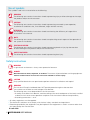
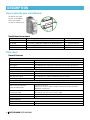
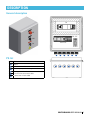
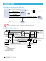
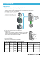
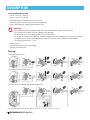
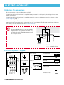
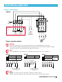
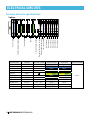
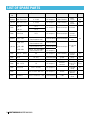
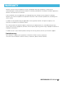
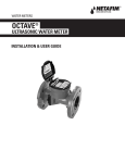
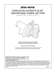
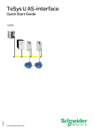
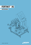
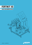
UNIVERSAL PUMP
SWITCHBOARD
USER MANUAL
V 001.05 - JUNE 2012
© COPYRIGHT 2012, NETAFIM
NO PARTS OF THIS PUBLICATION MAY BE REPRODUCED, STORED IN AN AUTOMATED DATA FILE OR MADE PUBLIC IN
ANY FORM OR BY ANY MEANS, WHETHER ELECTRONIC, MECHANICAL, BY PHOTOCOPYING, RECORDING OR IN ANY
OTHER MANNER WITHOUT PRIOR WRITTEN PERMISSION OF THE PUBLISHER.
ALTHOUGH NETAFIM TAKES THE GREATEST POSSIBLE CARE IN DESIGNING AND PRODUCING BOTH ITS PRODUCTS
AND THE ASSOCIATED DOCUMENTATION, THEY MAY STILL INCLUDE FAULTS.
NETAFIM WILL NOT ACCEPT RESPONSIBILITY FOR DAMAGE RESULTING FROM THE USE OF NETAFIM'S PRODUCTS OR
THE USE OF THIS MANUAL.
NETAFIM RESERVES THE RIGHT TO MAKE CHANGES AND IMPROVEMENTS TO ITS PRODUCTS AND/OR THE ASSOCIATED
DOCUMENTATION WITHOUT PRIOR NOTICE.
CONTENTS
Use of symbols
4
Safety instructions
4
Description
Functionality
Modularity and flexibility
Reliability
Easy and accessible maintenance
How to identify your switchboard
Data sheet
General description
PG list
Switchboard environment of operation
Switchboard block diagram
The TeSys LU
5
5
5
5
6
6
7
7
8
8
9
Electrical circuits
Control diagram
Guidelines for connections
Electrical symbols - Legend
Power connection - 3-phase
Terminal and wire specifications - 3-phase
Power connection - 1-phase
Terminal and wire specifications - 1-phase
11
12
12
13
14
15
16
Troublehooting
Switchboard warning light
No automatic start of the pump
The controller does not turn on
LU malfunction
17
17
17
17
List of spare parts
18
Warranty
19
SWITCHBOARD USER MANUAL 3
Use of symbols
The symbols used in this manual refer to the following:
WARNING
The following text contains instructions aimed at preventing injury or direct damage to the crops,
the product and/or the infrastructure.
CAUTION
The following text contains instructions aimed at preventing unwanted system operation,
installation or conditions that, if not followed, might void the warranty.
ATTENTION
The following text contains instructions aimed at enhancing the efficiency of usage of the
instructions in the manual.
NOTE
The following text contains instructions aimed at emphasizing certain aspect of the operation of
the system or installation.
ELECTRICAL HAZARD
The following text contains instructions aimed at preventing death or injury by electrocution
or direct damage to the product and/or the infrastructure.
SAFETY FOOTWEAR
The following text contains instructions aimed at preventing foot injury.
Safety instructions
WARNING
In agricultural environment - always wear protective footwear.
DANGER
Hazard of electric shock, explosion, or arc flash. Disconnect all power before servicing equipment.
Failure to follow these instructions will result in death or serious injury.
CAUTION
Only qualified electricians are permitted to perform electrical installations and repairs!
WARNING
The Universal Pump Switchboard does NOT provide protection against electrocution
since it does not include an earth-leakage circuit breaker.
The following items must be provided in the infrastructure:
• A readily accessible circuit breaker, rated according to the total rated power of the load, certified
as branch circuit over current protector compliant with the national code and requirements,
• Grounding connection: ≤ 10 Ω.
• All safety regulations must be applied.
• The electrical installation must comply with the local safety standards and regulations.
• Protection provided by the equipment may be impaired if the equipment is used in a manner other than
that specified by the manufacturer.
IP code: IP54
4 SWITCHBOARD USER MANUAL
DESCRIPTION
Functionality
The Universal Pump Switchboard is designed to activate the pump at a command from the controller,
provided there is sufficient water pressure in the mainline.
If the water pressure in the mainline is too low, a low-pressure signal is transmitted to the controller.
The controller may deactivate the pump.
The pump can be activated/deactivated manually via a manual override.
ATTENTION
If the pump is activated manually via a manual override, low-pressure protection is not active,
since it is also overridden.
It is also possible to disconnect the pump manually.
The Universal Pump Switchboard is equipped with 6 double-level terminals enabling the connection of the
command lines to the solenoides of the dosing channels in addition to the pump command line.
When connecting an external controller, use an 8-wire cable between the switchboard and the controller.
Modularity and flexibility
The switchboard is designed to operate with a large variety of:
Pumps:
• Single-phase pumps (0.5 kW to 2.2 kW)
• Three-phase pumps (0.75 kW to 15 kW)
Mains
• 1 x 100-250V
• 3 x 200-480V
Controllers
• 100-250V connected between phase and neutral
• 100-250V connected between two phases
• 100-250V from an external source
Reliability
• The switchboard is built of high quality components from internationally recognized manufacturers.
• The core of the switchboard is the TELEMECANIQUE's universal breaker TeSys U starter-controller,
also known as "LU".
Easy and accessible maintenance
• The switchboard's straightforward design enables easy and accessible maintenance.
• All its components are available locally in almost any place on the globe.
SWITCHBOARD USER MANUAL 5
DESCRIPTION
How to identify your switchboard
To identify the type
of your switchboard
check the imprint
on the LU control unit.
LUC
C 12
B
Switchboard assortment
Control unit inscription
LUCC12B
LUCB18B
LUCB12B
LUCB32B
Combination string
FSA-SWITCHBOARD-LUB12+LUCC12B-1PHASE
FSA-SWITCHBOARD-LUB32+LUCB18B-3PHASE
FSA-SWITCHBOARD-LUB12+LUCB12B-3PHASE
FSA-SWITCHBOARD-LUB32+LUCB32B-3PHASE
Switchboard Cat. No.
33230-500000
33230-500100
33230-500200
33230-500300
Data sheet
General features
Outputs
Feed to the controller voltage range
Feed to the controller current range
Fault signal
Dosing channel command
Inputs
Pump command
Dosing channel command
Low-pressure signal
Low-voltage supply
Safety / Protection
IP54
Short circuit or overload
in the controller feed
Short circuit or overload
in the pump feed
Phase imbalance
Red indication lamp
General features
Dimensions wxdxh
Weight
6 SWITCHBOARD USER MANUAL
1 X 100V to 1 X 250V (Jumper selection)
up to 1A
Dry contact N.O. when low water pressure or trip signal occurs
Up to 6 channels 24VAC
1 pump command 24VAC from the controller
Up to 6 channels 24VAC from the controller
Dry contact N.C. from an external pressure switch
24VAC 400mA from the controller for the control circuit
2 fuses of 1A each.
There are 2 fuses in order to allow connection of the controller
between two phases
Overload protection setting is adjustable in the
LU control unit within the current range
Applicable for 3-phase units
Lights in case of too low pressure or trip
27.6 x 18.1 x 32.5 cm (10.9" x 7.13" x 12.8")
4.5 kg (10 lb)
DESCRIPTION
General description
Q1
HF
RP RF
SM
Terminals
S0
1
2
3
2
3
4
5
6
PG list
PG
Cables
1
Mains
2
Mains to controller
3
Feed to pump and dosing channels
4
Dosing channel solenoide command cables
+ multi-wire command cable
+ pressure switch cable
5
6
1
4
5
6
SWITCHBOARD USER MANUAL 7
DESCRIPTION
Switchboard environment of operation
Low voltage power supply
for control circuit (24VAC)
LEGEND
Mains
Low voltage (24VAC)
Command line
Mains
Pump command
Controller
Universal
pump
switchboard
Power supply
Fault signal
Pump
Dosing channel command
Dosing channel command
Dosing
channel
Low
pressure
signal
Irrigation water main line
Pressure
switch
NOTE
If there is no controller, an external 24 VAC power supply must be provided.
Switchboard block diagram
Dosing
valve
command
Dosing
valve
command
Dosing
valves
Terminal
Controller
Manual pump command - ON Selector
OFF
Auto pump
command
SM
Fuse
LU
Control
unit
LU
auxiliary
contact
Pump
command
Low voltage power supply
for control circuit (24VAC)
Fault signal
Trip signal
or
Low pressure signal
HF
Fault indication lamp
LEGEND
Mains
Low voltage (24VAC)
Command line
Scope of delivery
8 SWITCHBOARD USER MANUAL
Q1
LU
base
Pump
power Pump
supply
Trip
signal
Relay RF
Relay RP
Low
pressure
signal
Pressure
switch
Main
switch
S0
Mains
DESCRIPTION
The TeSys LU
The TeSys U at the heart of the Universal Pump Switchboard
replaces conventional components in a smaller space
• The TeSys U starter-controller incorporates all the conventionally associated functions:
circuit breaker + contactor + thermal relay.
• It considerably reduces wiring time.
• The electircal coordination of the
components is intrisically ensured.
Equivalent to
Advantages
• Space-saving
• Time-saving
• Safety
The TeSys LU is composed of the following modules:
• LUB power base
This power base incorporates the power components: thermal blocks,
switching mechanism and power contacts. It also incorporates the
auxiliary contacts (terminal block not included).
• LUC supervisable control unit
Detection / tripping / measurement.
LUB
LUC
• LUA signalling contacts
Indicates that the protective device has tripped.
LUA
The TeSys LU - Combinations for the operation of the pump
Power base
LUB 12
(Up to 12A)
LUB 32
(Up to 32A)
Control
Command
unit
voltage
1-phase
24VAC
LUCC12B
3-phase
24VAC
LUCB12B
3-phase
24VAC
LUCB18B
3-phase
24VAC
LUCB32B
Current
range
3–12A
3–12A
4.5–18A
8–32A
Voltage range
1 X 100V
to 1 X 250V
3 X 200V
to 3 X 480V
3 X 200V
to 3 X 480V
3 X 200V
to 3 X 480V
Overload motor protection
1.1kW
2.2kW
at 1 X 100-115V at 1 X 200-250V
3.5kW
7kW
at 3 X 200-220V at 3 X 400-480V
5kW
9kW
at 3 X 200-220V at 3 X 400-480V
9kW
15kW
at 3 X 200-220V at 3 X 400-480V
*For other combinations, call Netafim.
SWITCHBOARD USER MANUAL 9
DESCRIPTION
Control and diagnostic unit
• LUCB - Class 10 - 3-phase
• LUCC - Class 10 - 1-phase
• Protection against overloads and short-circuits.
• Protection against phase failure and phase imbalance.
• Earth fault protection (equipment protection only).
WARNING
The Universal Pump Switchboard does NOT provide protection against electrocution
since it does not include an earth-leakage circuit breaker.
The following items must be provided in the infrastructure:
• A readily accessible circuit breaker, rated according to the total rated power of the load, certified
as branch circuit over current protector compliant with the national code and requirements,
• Grounding connection: ≤ 10 Ω.
• Manual reset.
• Fault differentiation with manual reset.
• Thermal overload alarm.
Test trip
Test trip magnetic fault
Test trip thermal overload fault
Test trip thermal overload fault by energized LUC
For full documentation on the TeSys LU, see www.schneider-electric.com
10 SWITCHBOARD USER MANUAL
ELECTRICAL CIRCUITS
Control diagram
800FP-SM32
“0”
Auto
Man.
3
3
SM
4
11
11
Q1 97
LUA1C20 RP RF
14
98
14
N24
P24
A1
Power
supply
Analog input
24
A2
X1 Fault
indication
X2 lamp
Red
HF
DO1
COM
COM
COM
V4
V5
V6
V1
V2
V3
V4
V5
V6
DO2
DO3
DO4
DO5
Digital output
24VAC
EC(AI1) pH(AI2)
DO6
DO7 COM
Fault to controller
AL1
COM
AL2
6
V3
5
COM
4
V2
3
COM
2
V1
103
102
101
N.C.
Low
pressure
protection
(presostat)
21
Dosing channels
Pump command
from controller
24 VAC
Power supply
from controller
to switchboard
24 VAC
P24
N24
Fuse
1A
RF
A1
LU9BN11
1
Fuse
1A
24
RF
IN2
COM
RP
21
4
A1
Q1 LUC***BL
A2
A2
RP
Digital
input
Controller
P24
EC
N24
EC/pH
transducer
pH
LEGEND
Scope of delivery
WARNING
The low voltage lines (24 VAC) must come from the same controller that issues the command
for the pump.
WARNING
The polarity of the low voltage lines (24 VAC) must be observed - N24 = common from controller.
SWITCHBOARD USER MANUAL 11
ELECTRICAL CIRCUITS
Guidelines for connections
All the commands to the switchboard are 24 VAC
If the Universal Pump Switchboard is supplied factory-installed in a dosing unit, the dosing channels are
already connected.
If the Universal Pump Switchboard is supplied separately, connect the dosing channels as shown in the
Control Diagram, page 11.
COM
When connecting the "Fault to controller" command line, make sure to program in the controller so that
upon receiving a pump deactivation command from the switchboard, the controller deactivates the pump
with a delay of a few seconds (see the Controller Manual).
V
NOTE
When multiple dosing units are operated by a
single controller (as typical of the NMC XL),
the dosing channel solenoides are connected
via a relay, as shown.
SSR
DO COM
Dosing
channel
LEGEND
Scope of delivery
Electrical symbols - Legend
Relay
Q1
Main switch
A1
5/L3
3/L2
1/T1
LUB unit
0 1
R
A2
97
98
Dosing solenoid
2 4 6
Booster pump
6/T3
4/T2
2/T1
U V W
12 SWITCHBOARD USER MANUAL
P
Modular terminal
Double level
terminal
Selector
V
LUC***B
Fuse terminal
1 3 5
SM
Terminal
“0”
Man.
3
4
Auto
3
4
220/110V
Transformer
24VAC
Internal wire
External wire
Related contact
ELECTRICAL CIRCUITS
Power connection
2
0 1
6
8
5/L3
Q1
10
97
98
5
7
See power L
connection 1
options
L
2
L
3
L L/N
4 5
Main
supply
9
Feed to
controller
6
LUC***B
L L/N
7 8
Power
supply to
controller
6/T3
3
4/T2
1
2/T1
SO
5 X 25A
4
3/L2
1/T1
3-phase
U
V
W
0
P
Power connection options
Pump
WARNING
When connecting the mains and the controller to the switchboard power terminals,
make sure the jumpers are placed correctly according to the mains and the controller voltage.
A jumper incorrectly connected might damage the controller!
NOTE
The switchboad exits the factory with a jumper connecting L3 to L4, as in option A.
3 X 400 V
Option
A
Option B
Option
C V
Controller
230 V
3 X 440
Mains
Controller
Mains
Controller
Controller
3 X 220 Mains
V
3 X 220 V
3 X 220 V
230 V
3 X 400-480
230 V
3 X 200-240
230 V
3 X 400-480
V
Controller
- external
Controller
230 V V
Controller
115 V V
0r
230
V
/
115
V
3 X 200-240 V
115 V
3 X 200-240 V
115 V
No jumper
External controller - No jumper
L L L L L/N
L L L L L/N
1 2 3 4 5 6
1 2 3 4 5 6
L L L L L/N
1 2 3 4 5 6
L1 L2 L3
N
Jumper position
3-4
L1 L2 L3
L1 L2 L3
L L/N
Jumper position
3-4 / 2-5
NOTE
Option C - In some cases the controller is fed by an external source,
usually in the USA, Mexico, Central America (some areas),and India (some areas).
SWITCHBOARD USER MANUAL 13
ELECTRICAL CIRCUITS
Terminal and wire specifications
Voltage
220 - 440 V
110 - 220 V
110 - 220 V
GND
220 - 440 V
GND
24 VAC
24 VAC
24 VAC
24 VAC
24 VAC
24 VAC
14 SWITCHBOARD USER MANUAL
Terminal symbol
L1. L2. L3
L4
L/N
U. V. W
P24
N24
101 - 103
AL1 - AL2
V1 - V6
COM
V1
V2
V3
V4
V5
V6
COM
COM
COM
COM
COM
COM
Dos. channel 1
Dos. channel 2
Dos. channel 3
Dos. channel 4
Dos. channel 5
Dos. channel 6
Pressostat (pressure switch)
Booster pump command
Fault to controller
From controller 24VAC
Pump
4 5 6 7 8
Terminal block
Modular
Modular
Modular
Ground
Modular
Ground
With LED fuse
With LED fuse
Double-level
Double-level
Double-level
Double-level
L L/N U V W
To controller
1 2 3
External supply (optional)
L L/N
Main supply
L L L
P24
N24
102 101
103
AL2 AL1
3-phase
Terminal color
Gray
Black
Black
Yellow + green
Gray
Yellow + green
Black
Black
Gray
Gray
Gray
Gray
Wire color
Brown
Black
Black
Yellow + green
Brown
Yellow + green
White
Gray
White
White
White
Gray
Terminal section
4 mm
ELECTRICAL CIRCUITS
Power connection
2
0 1
4
6
5/L3
3/L2
1/T1
1-phase
Q1
8
97
98
5
See power L L/N
connection 1 2
options
Main
supply
7
L L/N
3 4
Feed to
controller
5
L
6
LUC***B
N
7
Power
supply to
controller
L
8
Power connection options
6/T3
3
4/T2
1
2/T1
SO
5 X 25A
L/N
9 10
P
Pump
WARNING
When connecting the mains and the controller to the switchboard power terminals,
make sure the jumpers are placed correctly according to the mains and the controller voltage.
A jumper incorrectly connected might damage the controller!
NOTE
The switchboad exits the factory with jumpers connecting L1 to L3 and L/N2 to L/N4, as in option A.
1 X 220 V
Option
A
Option B
Controller
230 V
2 X 440 V
Mains
Controller
Mains
Controller
2 X 220 V
2 X 220 V
230 V
1 X 200-250
230 V
1 X 100-250 V
Controller
230 VV
Controller - external 0r
2302 VX /200-240
115 V V
X 200-240
V
230 V
115 V
2 X2220
V
No
jumper
External controller - No jumper
1 X 100-115
115 V
Controller
115 VV
L L/N
1 2
L L/N
3 4
5
L L/N
1 2
L L/N
L L/N
3 4
5
L L/N
L L/N
Jumper position
1-3 / 2-4
NOTE
Option B - In some cases the controller is fed by an external source,
usually in the USA, Mexico, Central America (some areas),and India (some areas).
SWITCHBOARD USER MANUAL 15
ELECTRICAL CIRCUITS
Terminal and wire specifications
Terminal block
Modular
Modular
Modular
Modular
Ground
With LED fuse
With LED fuse
Double-level
Double-level
Double-level
Double-level
Voltage
Terminal symbol
110 - 220 V
L1, L3
110 - 220 V
L/N
External voltage
L6, L8
External voltage
L/N
GND
24 VAC
P24
24 VAC
N24
24 VAC
101 - 103
24 VAC
AL1 - AL2
24 VAC
V1 - V6
24 VAC
COM
16 SWITCHBOARD USER MANUAL
V1
V2
V3
V4
V5
V6
COM
COM
COM
COM
COM
COM
Dos. channel 1
Dos. channel 2
Dos. channel 3
Dos. channel 4
Dos. channel 5
Dos. channel 6
8 9 10
Pressostat (pressure switch)
Booster pump command
Fault to controller
L L/N
From controller 24VAC
To controller
3 4 5 6 7
External supply (optional)
Main supply
1 2
L L/N
Pump
L L/N L L/N
P24
N24
102 101
103
AL2 AL1
1-phase
Terminal color
Gray
Blue
Black
Black
Yellow + green
Black
Black
Gray
Gray
Gray
Gray
Wire color
Brown
Blue
Black
Black
Yellow + green
White
Gray
White
White
White
Gray
Terminal section
4 mm
TROUBLESHOOTING
Switchboard warning light
• The switchboard warning light is on (whether the dosing booster is running or not).
Action
1)
Check if the pressure on the main line is too low:
If YES, restore the original main line pressure.
2)
Check if the overload protection breaker is ON.
Toggle it OFF and ON again.
If the switchboard warning light is still on or the overload protection breaker trips (turns to OFF) again,
have a qualified electrician check that the dosing booster is in working order (see the Dosing Booster
Manual) and check for irregularities in the mains.
3)
Check if the overload protection setting of the LU is set according to the pump consumption.
If after implementing all the above steps, the malfunction is still not fixed - consult your Netafim representative.
No automatic start of the pump
• Automatic activation of the pump does not function.
Action
1)
Set the selector switch (SM) to MANUAL.
If the pump still does not function, check the fuses (See List of Spare Parts, page 18)
and replace if necessary.
2)
If the pump still does not function, check whether:
a) The main switch (SO) is set to MANUAL.
b) The selector switch (SM) is not set to AUTO.
c) The LU circuit breaker is set to OFF.
d) The cable to the controller is disconnected or defective.
e) The low voltage (24 VAC) from the controller to the switchboard is inversely connected (N to P) if necessary, reverse it .
f) There is a malfunction of the controller (see the Controller Manual).
If after implementing all the above steps the malfunction is still not fixed - consult your Netafim representative.
The controller does not turn on
• The controller does not receive power supply from the mains.
Action
1)
Make sure the jumpers are placed correctly according to the mains and the controller voltage.
(For 3-phase installation see page 13, for 1-phase installation see page 15).
WARNING
A jumper incorrectly connected may damage the controller!
LU malfunction
• If after implementing all the actions regarding any of the malfunctions above, the malfunction is still not fixed,
it is possible that the reason is a malfunction of the LU (for full documentation on the TeSys LU,
see www.schneider-electric.com).
SWITCHBOARD USER MANUAL 17
LIST OF SPARE PARTS
Suitable Type/model
for
Technical data
Cat. number
Manufacturer
1-phase 194L-E16-1754
4 X 16A
On request
Allen Bradley
3-phase 194L-E25-1755
5 X 25A
On request
Allen Bradley
On request
Telemecanique
Both
LUB 12
or
LUB 32
12 A
Both
LUA1C20
N.O.
32 A
Accessory Symbol
Main
switch
Main
switch
Telemecanique
3-12A, 1 X 100-250V
Command 24 VAC
3-12A, 3 X 200-480V
77100-013600
LUCB 12B
Command 24 VAC
or
4.5-18A, 3 X 200-480V
LU control
77100-013620 Telemecanique
3-phase LUCB 18B
Command 24 VAC
unit
or
8-32A,
3
X
200-480V
LUCB 32B
On request
Command 24 VAC
Selector
Both
800 FP - SM32
6A
On request
Allen Bradley
switch
Both
40.52
24 VAC
77100-001460
Finder
Relay
Both
40.52
24 VAC
77100-001460
Finder
Relay
Terminal
Phoenix
with LED
Both
UK5 - HESI
1A
On request
contact
fuse
Indicator
Both
PL16-22D
LED - 24 VAC
On request
lamp
Electrical
Both
276 X 154 X 181 mm
On request
Hi box
board
Spare
Both 179 020.1
Glass 5 X 20 mm - 1AF 77100-000470
Siba
fuse
1-phase LUCC 12B
18 SWITCHBOARD USER MANUAL
S0
LU base
Fault aux.
contact
+ terminal
LU control
77100-013640 Telemecanique
unit
On request
S0
Q1
SM
RP
RF
Fuse
HF
WARRANTY
Netafim warrants all the components of the switchboard to be free of defects in material and
workmanship for 1 (one) year from the date of installation, provided the installation has been reported to
Netafim within 30 days of installation.
If the installation was not reported or was reported later than 30 days from the date of installation,
Netafim will warrant the product for a period of 18 months from the date of production, according to its
serial number.
If a defect is discovered during the applicable warranty period, Netafim will repair or replace, at its
discretion, the product or the defective part.
This warranty does not extend to repairs, adjustments or replacements of a switchboard or part that
results from misuse, negligence, alteration, force majeure, lightning, power surge, improper installation or
improper maintenance.
If a defect arises in your Netafim product during the warranty period, contact your Netafim supplier.
Limited warranty
This warranty is subject to the conditions in Netafim's official warranty statement.
(For the full text of Netafim's official warranty statement, please contact Netafim).
SWITCHBOARD USER MANUAL 19
20 SWITCHBOARD USER MANUAL
GROW MORE WITH LESS
WWW.NETAFIM.COM