1
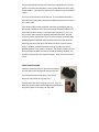
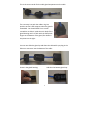
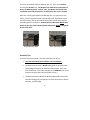
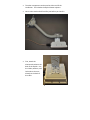
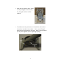
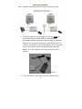
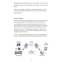
 ZipLink
Wireless Phone Line & Ethernet Extender User Guide v.5 Multi‐Link, Inc. 122 Dewey Drive | Nicholasville, KY | 40356 USA Sales and Tech Support 800.535.4651 FAX 859.885.6619 1
Statement of Conformity Note: This equipment has been tested and found to comply with the limits for a Class A digital device, pursuant to part 15 of the FCC Rules. These limits are designed to provide reasonable protection against harmful interference when the equipment is operated in a commercial environment. This equipment generates, uses, and can radiate radio frequency energy and, if not installed and used in accordance with the instruction manual, may cause harmful interference to radio communications. Operation of this equipment in a residential area is likely to cause harmful interference in which case the user will be required to correct the interference at their own expense. This device complies with Industry Canada license ‐exempt RSS standard(s). Operation is subject to the following two conditions: (1) this device may not cause interference, and (2) this device must accept any interference, including interference that may cause undesired operation of the device. 2
Technical Support Contact:
1‐800‐535‐4651 techsupport@multi‐link.net *Safety Warnings for Grounding and RF exposure* In order to comply with electrical codes in most areas, as well as provide adequate protection from lightning, you MUST ground the ZipLink outdoor unit! This device contains a low power radio transmitter. When this device is connected and transmitting, it sends out Radio Frequency (RF) signals. This Wireless Radio device has been evaluated under FCC Bulletin OET 65C and found to be compliant to the requirements as set forth in CFR 47 Sections 2.1091, 2.1093, and 15.247(b)(4) addressing RF Exposure from radio frequency devices. The radiation output power of this wireless device is far below the FCC radio frequency exposure limits. Nevertheless, this device should be installed and used in such a manner that limits the potential for human exposure to distances greater than 20 cm or 8 inches from the device. This device should not be installed within 10 meters / 30 feet of any other RF transmitter. 3
Contents
Statement of Conformity.............................................................................2 Technical Support ........................................................................................3 Safety Warnings for Grounding and RF exposure .......................................3 Contents ......................................................................................................4 Introduction.................................................................................................5 Box Contents................................................................................................5 Cabling .........................................................................................................5 Cable Gland Assembly .................................................................................6 Bench Testing ..............................................................................................8 Installation ...................................................................................................8 Assembly Tips ..............................................................................................9 Electrical Connections ...............................................................................12 Aiming the antennas..................................................................................14 Bench Testing ............................................................................................14 Startup / Testing ........................................................................................15 System Diagram.........................................................................................16 Warranty....................................................................................................19 Disclaimer ..................................................................................................19 4
Introduction The Multi‐Link ZipLink is a wireless system that comes in two different models. The ZipLink‐1 allows one standard analog (POTS) phone line and an Ethernet LAN (internet) connection to be extended between two locations up to 1 mile / 1.6 kilometers apart. The ZipLink‐2 has identical functionality, but for two phone lines. The ZipLink is designed to be quickly and easily installed. You will need the following tools: ‐
‐
‐
Power Drill / Screwdriver w/ Phillips bits 10mm nut driver / wrench Electrician’s fishline Box Contents The Multi‐Link ZipLink box contains the following: ‐
‐
‐
‐
2 ZipLink Outdoor Radios, Master & Remote, with outdoor cable 2 power adapters 2 Antenna Mounts Accessory Kit (White Box) Cabling Each ZipLink radio comes equipped with 30 Meters / 100 feet of OUTDOOR RATED cable which runs from the ZipLink to the Power / POTS Power Injector, which is usually mounted indoors. The cable is used for the POTS connections as well as power. YOU MAY SHORTEN THIS CABLE IF YOU WISH, BUT YOU MAY NOT LENGTHEN IT. Keep in mind that this cable length maximum distance is due to the maximum length allowable for the power wires inside this cable only. The cable length FROM the Multi‐Link power injector POTS RJ11 connector TO the telco line, PBX or deskset may be up to 300 feet in total 5
using unshielded twisted pair CAT3 cable for the telephone circuits and CAT5E or CAT6 for Ethernet/data, or even greater distances when using shielded cables. This allows for almost any installation to use the ZipLink system. There are two connections to the ZipLink. The precabled connection is the POTS line(s) and power, the bottom middle weatherproof connector is for Cat5E data. Each outdoor ZipLink radio should be electrically grounded by use of a ground lug installed on one of the bolts used to hold the ZipLink on the pole mount brackets and run to a proper electrical ground. This is not only a safety requirement for lightning dissipation purposes, but also improves system radio performance, since the enclosure provides radio shielding against unwanted radio and electrical noise on the POTS line. Assuming that the outlet which the Multi‐Link Power Injectors power supply is properly installed according to electrical codes, no further grounding points in the system is required. The electrical circuits for the POTS and Ethernet/Data connections should NEVER be grounded. This includes all connections in the power injector. POTS Phone connections “float”. Cable Gland Assembly Inside the accessory box that came with the ZipLink, you will find 2 black cable glands that look like this: You should unscrew the two parts. You should leave the small rubber O‐ring where it is. You will notice that the O‐ring has a slit in it. This is to allow the Ethernet cable to be completely assembled on the ground, prior to installing it on the radio. 6
This is the correct order for the cable gland components on the cable: The next step is to push the rubber ring into position so that it will compress when the gland is assembled. You should GENTLY use a small screwdriver to slide it inside the main body of the gland housing until it is flush with the little plastic fingers at the bottom of the gland, like shown in the picture to the right: You can now slide the gland up and down the cable while you plug in the Ethernet connector into the bottom of the radio: Screw in the gland housing: And then the bottom gland cap: 7
Bench Testing When bench testing the ZipLink, you need to know the following: ‐
The minimum distance between the radios MUST be 25 feet or 8 meters. If you have the Master and Remote ZipLink closer together than this during testing, the system may not operate properly, especially in modem testing. ‐
You should always orient the radios similarly to how they will be oriented when they are installed. Optionally, you may sit them BOTH sideways with the SKY arrow pointing at the same wall to facilitate easy RJ45 cable installation. ‐
Both units should be electrically grounded on their chassis to ensure noise from lights and motors in the vicinity do not affect call quality. Installation Mount the ZipLink Radios as high up as possible on both buildings. The radios must “see” each other without obstructions between them, and since the radio signals travel in a “football” shape between antennas, you must not only have a direct path between the antennas, but the path also must be wide enough, as determined by the distance between the radios: Radio height required by distance between radios Distance (mi./km) .25 / .40 .5 / .80 Minimum Height( ft/m) 10 / 3 14 / 4.3 1 / 1.6 19 / 6 For example, if you have two buildings a half mile apart, the ZipLink radios should be 14 feet above the ground, plus the height of anything else that is in between the buildings. So, if there are vehicles moving between the radios, they need to be 14 above the maximum height of the traffic, approx. 30 feet up. Same rule applies for trees, buildings, and other structures. 8
There are two ZipLink radios included in each kit. There is one Master unit and one Remote unit. The Remote unit needs to be connected to a Phone (or Modem) at the “remote” end. The Master unit needs to be connected to the PBX, Key System, or POTS line at the “main” location. Dial tone is locally generated on the Remote unit, so if you reverse the radios, you will not get dial tone at the Remote end. The fastest way to check if you have the correct radio at each end is to look at the color of the cable gland on the ZipLink. Remote ZipLink radios have BLACK cable glands on the telco cable. Master ZipLink radios have BEIGE cable glands on the telco cable: Beige (Master) Radio Black (Remote) Radio Assembly Tips There are two of everything. Here are some basic set up tips: •
The radio units MUST be installed at correct endpoint. •
The ZipLink unit that has a BLACK cable gland on the CAT3 cable should plug into a phone or modem or fax machine. (You may also say that this is the radio that goes to the REMOTE end, or the end that currently does not have phone service.) •
The ZipLink that has a BEIGE (or WHITE) cable gland on the CAT3 cable should plug into a telephone line (that comes from a phone company, or office PBX). 9
•
The other components can be used at either end of the installation. This includes the ZipLink Power Injectors. •
Here is what each end will look like just before you install it: •
First, attach the aluminum bracket to the back of the ZipLink. Use the 4 bolts, washers, and lock washers that are already on the back of the radio: 10
•
Next, put the U‐Bolts in place. These are also packaged in the Accessory Kit, along with washers and lock washers: •
The hardware for the pole mounts is included with the brackets themselves. Included are three bolts‐‐‐2 short, square‐flanged bolts and one long pivot bolt‐‐‐with nuts. Here is how you should put the pieces together prior to tightening anything: 11
Electrical Connections Here is a diagram of the ZipLink electrical connectivity(not to scale): •
The power adapters must be plugged into the wall AFTER the other connections have been made. The only difference (electrically) between the ZipLink‐1 and the ZipLink‐2 is that the ZipLink‐2 has connections to extend a second POTS line over the radio link. The ZipLink‐2 has a second “dongle” that is connected to the Power Injector for the second POTS circuit (see image below). In all other respects, the installation of the system is identical. ZipLink ‐2 •
It does not matter in what order the radios are powered up. 12
•
The weatherproof RJ45 connectors may be left unused, as long as you tighten them to ensure no moisture or contaminants get inside them. •
The RJ45 connection performance is approx. equal to an office network LAN connection. It is suitable for email, internet access, VoIP grade connectivity. •
The RJ‐45 connection on the Master side may be plugged into an office router, etc. If the Phone/Remote RJ45 connection is to be shared between computers, it is recommended that it is routed as well, to ensure LAN traffic between computers at the remote end does not go “over the air”, thereby affecting the performance of the wireless LAN connection by relaying unnecessary LAN traffic. •
When using the ZipLink with devices other than standard phones and telephone company lines, you need to be careful about the polarity in use. Some third party devices will not automatically switch when the line is reversed. •
Standard telephone cables have the two ends reversed. This means that red will be on pin 2 on one end and pin 3 on the other, and vice versa for green. •
If you have a phone cable that is a straight through cable, ie. Red is always pin 2 and green is always pin 3, it may cause an issue with the ZipLink operation. Standard phone cables reverse Red and Green. •
Even if you use a ZipLink only for the Ethernet capability, you MUST still run the provided Cat 3 cable inside to the power injector. The ZipLink does not support power over Ethernet . 13
Aiming the antennas Once you have completed the installation, try to get both radios pointing at the other as best as you can. It is essential that the radios are mounted in such a way that the cabling comes out the bottom (towards the ground). The ZipLink antennas allow up to 15 degrees variation in between the Remote and Master units left/right and up/down. Alignment does not have to be perfect to have the system work. For example, if your ZipLink Remote and Master units are 500 yards/meters apart, and one is mounted 5 feet higher than the other, and the left/right angle is out by 3 or 4 degrees, you will still have a good stable link. The TUtil ZipLink software can assist you in getting the best signal possible. Contact Multi‐Link Tech Support for the download link. Bench Testing When bench testing the ZipLink prior to doing a field installation, there are a few important things to know. First, the radios are designed to be at least 20 feet apart when in operation. It is possible to overdrive the radios if they are only a few feet apart and facing each other. Generally, it is okay to put both ZipLink radios on the bench facing upwards and a few feet apart when testing. This will bring the signal strength down to a reasonable level. When using the ZipLink with devices other than standard phones and telco lines, you need to be careful about the line polarity in use. Some third party devices will not automatically switch when the line connections are reversed. 14
Standard telephone cables have the two ends reversed. This means that Red will be on PIN 2 on one end and PIN 3 on the other, and vice versa for green. If you have a telephone cable that is a straight through cable, ie. Red is always PIN 2 and Green is always PIN 3, it may cause an issue with the ZipLink operation. Startup / Testing Once the antennas have been aligned, you may test the system by dialing in and out of the phone at the remote end. You do not need to do anything different than you would for any other phone that is on the system, with one exception. If your phone system requires you to dial “9” for an outside line, you need to dial the entire phone number with the leading 9 at one time, ie. 919165551212, instead of “9” (Wait for dial tone), then the number. This is called one stage dialing, and is the only method used with the ZipLink. If you are using the RJ45 data connection as well, you should be able to use your computer in exactly the same way you would at the other end.
15
Basic Troubleshooting •
TUtil ZipLink software is a program that will assist with the installation and configuration settings of the ZipLink system. The latest up‐to‐date software may be acquired from Multi‐
Link Technical Support (800‐535‐4651). There is no charge for this software. •
If you do not get a dial tone when you pick up the phone at the remote end, it is most likely that you either have no power to the Remote ZipLink radio, or have accidentally installed the Master unit at the remote end. Check that the Remote is plugged into a ZipLink unit with two black cable glands (one small and one large), and that the power adapters LED is illuminating when power is applied. •
If you are experiencing any kind of AC hum or noise during a phone call, this usually indicates that one of the outdoor units has not been properly grounded. You need to ground the outside chassis of the outdoor units in order to ensure a suitable path to ground in the case of a lightning strike, and to reduce spurious radio noise. •
Incoming ring forwarding delay is what happens to capture caller ID on incoming calls. If you dial into the remote site while you are right next to it, you will notice about two rings occur before the remote site phone at the Remote end will ring. This is required by the ZipLink to capture the caller ID information, which is supplied after the first ring by the phone company, prior to completing the call to the remote site’s phone. This is normal. 16
•
Grounding – The ZipLink is considered to be a low voltage device, and therefore usually may be installed by anyone without need for permits or inspections. However, you need to make certain the outside case is grounded for lightning, and you should consult your local electrical / safety codes in your area prior to performing any kind of permanent equipment installation. Additionally, the ZipLink Power Injector lid can be removed if you want to either permanently screw it to the communications room wall, or directly run telephone wire to the unit. However, DO NOT GROUND ANY CONNECTIONS INSIDE THE ZipLink POWER INJECTOR. The green wire inside the ZipLink Power Injector is a floating POTS phone signal – the system will malfunction if you ground it! •
Use with Modems – The ZipLink has been tested up to 2400 bps using standard modems and phone lines. In many cases, higher data rates can be obtained due to compression that is automatically provided by the modem protocol. To improve dial up connection times and reliability, you should set the maximum connect speed for a ZipLink connected remote site to 2400 bps. These commands may vary by your particular modem manufacturer. •
ZipLink systems that are shipped pre‐programmed for operation with modems have a MODEM sticker on the shipping box. If you are uncertain what kind of ZipLink you have, or if you want to change a ZipLink from a Voice/Fax unit to a Modem‐optimized unit, you will need to contact Multi‐Link technical support @ 800‐535‐4651 for assistance. 17
•
It is important to understand that each ZipLink system is programmed to ONLY talk to itself. If you have two ZipLink systems, you cannot mix and match Remote and Master units. •
The ZipLink does not currently support distinctive ring. If you require servicing two Phone/Remote numbers from the same line, there are accessory products that may be used in conjunction with the ZipLink‐2 to create a second line occurrence. Please contact Multi‐Link support for details. •
If you are experiencing voice or data performance problems, there is a possibility that the ZipLink is getting interference from another wireless network near the site. To check if this is the case download and install on a laptop computer a program called inSSIDer from the following link: http://www.metageek.net/products/inssider/ Please contact Multi‐Link support for details on this or similar programs. •
Fax – The ZipLink supports fax machine receive and transmit up to 14.4kbps. •
Should you wish to remove the original ZipLink sticker from the front of the outdoor unit and replace it with something else, please ensure that anything applied to the front of the ZipLink radio allows high frequency radio to pass through. You cannot use labels that have any kind of metallic based inks, or a foil label without harming the ZipLink, or seriously degrading its performance.
18
Warranty Multi‐Link warrants the ZipLink system for one year from date of purchase by the original owner. Multi‐Link will replace or repair, at its option, any ZipLink system that fails to perform under normal use, provided that the system is returned, at the cost of the owner, to Multi‐Link. Items that are returned for warranty repair must be accompanied by a copy of the original invoice or proof of purchase. For further details about how to receive warranty or after warranty service information, please contact your Multi‐Link distributor, or visit the Multi‐Link website at www.Multi‐Link.net. Any operation of the ZipLink outside of specified temperatures, power, environment, or in a manner specified in this manual as harmful to the device will void any warranty. Additionally, any attempted repair or dismantling of any Multi‐Link product, in any way, will void all warranties. In no event shall Multi‐Link liability exceed the original purchase price of the product from direct, indirect, special, incidental, or consequential damages resulting from the use, or misuse, of this product. Disclaimer Installation of this equipment must be in strict accordance with the instructions included in this documentation. Any changes or modifications made to this device that is not expressly approved by Multi‐Link may void the user’s authority to operate the equipment. 19
Specifications Radio Range 1 Mile / 1.6 km POTS Line 1 or 2 regular analog REN 8 Ethernet Port RJ45 / 10BT equivalent Fax Speed 14.4 kbps Modem Speed (Modem Version) Up to 2400 bps Operating Temperature ‐30F to +145F Power Required 120VAC / 7W, (ZipLink) / 10W (ZipLink 2) Radio Type 5.8 GHz DSSS, License Free Encryption 256 Bit WPA2‐PSK (AES) Radio Power +41 dBm Radio Sensitivity ‐89 dBm @ 10‐5 BER Outdoor Unit Size 9” x 9” x 3.5” (23cm x 23cm x 9cm ) System Shipping Weight Shipping Dimensions 24” x 11” x 8.75” 23 lbs / 10.5 kg ( 61cm x 28 cm x 22 cm ) 20