1
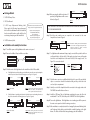
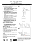
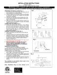
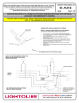
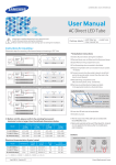
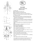
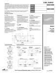
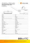
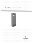
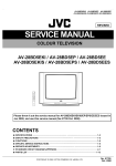
LDFT8 Instruction
THIS DEVICE IS NOT INTENDED FOR USE WITH EMERGENCY EXITS.
LDFT8
Installation Guide
Important Safety Instructions
This product must be installed in accordance with the applicable installation code by
a person familiar with the construction and operation of the product and the hazards
involved.
WARNING - Risk of fire or electric shock. LED Retrofit kit installation requires
knowledge of luminaires electrical systems. If not qualified, do not attempt
installation. Contact a qualified electrician.
WARNING – Risk of fire or electric shock. Install this kit only in luminaires that have the
construction features and dimensions shown in the photographs and/or drawings.
and where the input rating of the retrofit kit does not exceed the input rating of the
luminaire.
Do not make or alter any open holes in an enclosure of wiring or electrical
components during kit installation.
WARNING – To prevent wiring damage or abrasion, do not expose wiring to edges of
sheet metal or other sharp objects.
WARNING – To avoid potential fire or shock hazard, do not use this retrofit kit in
luminaires employing shunted bi-pin lampholders.
NOTE – Shunted lamp holders are found only in fluorescent luminaires with InstantStart ballasts. Instant-start ballasts can be identified by the words “Instant Start” or
“I.S.” marked on the ballast. This designation may be in the form of a statement
pertaining to the ballast itself, or may be combined with the marking for the lamps
with which the ballast is intended to be used, for example F40T12/IS. For more
information, contact the LED luminaire retrofit kit manufacturer.
Installer should not disconnect existing wires from Lampholder terminals to make
new connections at Lampholder terminals. Instead installers should cut existing
Lampholder leads away from the Lampholder and make new electrical connections to
Lampholder lead wires by employing applicable connectors.
This luminaire has been modified and can no longer operate the originally intended
lamp.
Intended for use with maximum 4 lamps in a recessed luminaire with or without
diffuser. Intended for use with maximum 2 lamps in a surface mount luminaire with or
without diffuser.
Suitable for damp locations
Do not use with dimmers
Suitable for use in enclosed luminaires
Double insulation
General
Operating Input Voltage
100 - 277 Vac, 50 - 60Hz
Power Factor
>0.9 (100 - 240 Vac)
>0.87 (277Vac)
Color Temperature
3500K / 4000K / 5000K
Power Consumption
8W (LDFT8Z8)
16W (LDFT8Z16)
Operating Temperature
-20 to 45˚C
Storage Temperature
-40 to 80˚C
Operating Humidity
>90% (RH)
Cap Base
G13
Specification (Outline Drawing)
C
A
B
Tube Length
Dim A (Max)
Dim B
Dim C
2FT
589mm
603mm
27mm
4FT
1199mm
1213mm
27mm
LDFT8 Instruction
Lampholder A
Package Details
Step 4: After removing the ballast and starter (if
provided), the light fixture will be seen as
below (see Figure 5).
1. 10 PCS LED Lamp Tubes.
2. 1 PCS User Manual.
3. 10 PCS Lamp Replacement Marking Label.
Please apply the following lamp replacement
label on the retrofit luminaire after the retrofit kit
has been installed, where readily visible by the
user during re-lamping and after installation.
This luminaire has been modified and can no
longer operate the originally intended lamp.
Replace with Ohyama Lights LLC,
Model [LDFT8Z8/LDFT8Z16].
Tel: +262-925-6505,
Email: [email protected]
http://www.ohyamalights.com
4. 10 PCS Cautionary Label.
Min lamp to lamp spacing: 8.5cm
Figure 8
Figure 7
Recessed Luminaire
If the light fixture is providing with magnetic ballast and starter, disconnect and rewiring the
wires at the point as shown in the following figures (see Figure 1 to Figure 2)
Lampholder B
S
Ballast
Usually Black Wire
Starter
Usually White Wire
(L)+
Lampholder A
Lampholder B
S
Ballast
Usually Black Wire
Starter
Usually White Wire
(L)+
(N)-
Figure 1: Before retrofit.
(N)-
Figure 2: Under retrofit - Cut the wires connected to the
ballast and starter, and Lampholders as
shown. [ ] Remove the ballast and starter.
If the light fixture is providing with electronic ballast, disconnect and rewiring the wires at
the point as shown in the following figures (see Figure 3 to Figure 4).
Lampholder A
Lampholder B
Lampholder A
Lampholder B
Ballast
Usually Black Wire
Usually White Wire
(L)+
(L)+
(L)+
Step 3: Check the wires of the light fixture before installation of the LED retrofit kit.
Figure 3: Before retrofit.
(N)+
Figure 6: After retrofit – Rewiring the wires from Lampholder
A to “L” and “N” of the supply circuit by wire nuts /
connectors. Insulated or capped all unused
conductors with a wire connectors.
Step 6: For light fixture with maximum 4 lamps, simply connect all the positive leads from
each Lampholders to the line side (L) of the supply circuit and connect all negative
leads from each Lampholders to the neutral side (N) of the supply circuit. See
Figure 7 for connection details.
Surface Mount Luminaire
b.
Usually White Wire
(L)+
Min lamp to lamp spacing: 2.54cm
Lampholder A
(N)-
Ballast
Usually Black Wire
Usually White Wire
(L)+
(N)+
Lampholder B
Usually Black Wire
Lampholder
a.
Usually White Wire
(L)+
Step 5: Both line and neutral power are required to be connected to the same
Lampholder as shown in Figure 6
Lampholder A
Step 2: Remove the diffuser (if any) and fluorescent tube.
Usually Black Wire
Figure 5
FOR LED RETROFIT KIT WHICH BOTH LINE AND NEUTRAL POWER ARE CONNECTED
TO THE SAME LAMPHOLDER.
Installation or Assembly Instructions
Step 1: Turn off the power to the light fixture at the main service panel.
Lampholder B
(N)-
Figure 4: After removing the ballast and starter (if
provided), the light fixture will be seen as
below (see Figure 5).
(N)-
(N)Live End
Live End
Step 7: Check the wire connectors carefully which shall not be loosened. Be sure that the
splices or connections should be insulated reliably, and they should be in the
enclosed splice compartment.
Step 8: Identify one side of the Lampholder which connected to the supply circuit as the
“LIVE END” and mark for future reference.
Step 9: Install the LED Lamp Tube to light fixture matching the power side (the side
marked with “L” and “N”) of the lamp to the “LIVE END” side of the light fixture.
Step 10: Turn on the light fixture. If the light fixture is not working, turn off the power at
the main service panel and check the wiring connections.
Step 11: After modification completed, attach the Lamping Replacement Marking Label
and Cautionary Label which provided with the retrofit kit package to the light
fixture. The labels shall be visible during relamping, and after installation.