1
AV-28BD5EKI AV-28BD5EP AV-28BD5EE
AV-28BD5EKIS AV-28BD5EPS AV-28BD5EES
REVISED
SERVICE MANUAL
COLOUR TELEVISION
AV-28BD5EKI / AV-28BD5EP / AV-28BD5EE
AV-28BD5EKIS / AV-28BD5EPS / AV-28BD5EES
Please throw it out the service manual for AV-28BD5EKI/EKIS/EP/EPS/EE/EES issued in
Jun 2000, and use this service manual (No.51709 Oct. 2000).
CONTENTS
!
!
!
!
!
★
!
1
SPECIFICATIONS ・・・・・・・・・・・・・・・・・・・・・・・・・・・・・・・・ ・・・・・・・・・・・・・・・・・・・・・・・・・・・・ 1-2
SAFETY PRECAUTIONS ・・・・・・・・・・・・・・・・・・・・・・・・・・・・・・・・ ・・・・・・・・・・・・・・・・・・・・・・ 1-5
FUNCTIONS ・・・・・・・・・・・・・・・・・・・・・・・・・・・・・・・・ ・・・・・・・・・・・・・・・・・・・・・・・・・・・・・・・・ ・ 1-6
SPECIFIC SERVICE INSTRUCTIONS ・・・・・・・・・・・・・・・・・・・・・・・・・・・・・・・・ ・・・・・・・・・・・・ 1-8
SERVICE ADJUSTMENTS ・・・・・・・・・・・・・・・・・・・・・・・・・・・・・・・・ ・・・・・・・・・・・・・・・・・・・・・ 1-9
STANDARD CIRCUIT DIAGRAM (APPENDIX) ・・・・・・・・・・・・・・・・・・・・・・・・・・・・・・・・ ・・・・・ 2-1
PARTS LIST ・・・・・・・・・・・・・・・・・・・・・・・・・・・・・・・・ ・・・・・・・・・・・・・・・・・・・・・・・・・・・・・・・・ 1-13
COPYRIGHT © 2000 VICTOR COMPANY OF JAPAN, LTD.
No. 51709
Oct. 2000
AV-28BD5EKI AV-28BD5EP AV-28BD5EE
AV-28BD5EKIS AV-28BD5EPS AV-28BD5EES
SPECIFICATIONS
Item
Content
TV RF SYSTEM
B/G, I, D/K & L/L’
COLOUR STANDARD
PAL / SECAM / NTSC (AV only)
POWER INPUT
AC 230V, 50Hz
POWER CONSUMPTION
75W / 3W (Stand-by)
TELETEXT SYSTEM
FLOF (Fastext) / TOP / WST (standard system)
SOUND OUTPUT / SPEAKER
7W / 8Ω (×2)
PICTURE TUBE SIZE
VISIBLE AREA 66cm (measured diagonally)
ANTENNA INPUT
75Ω Unbalanced
NPUT / OUTPUT
FRONT [AV2]
:
REAR [AV1 / AV2] :
RCA JACK (VIDEO / AUDIO)
21-PIN EURO CONNECTOR (SCART)×2
(VIDEO / AUDIO / RGB / S. VHS)
AV2 Input terminals in front and rear side are common
INTERMEDIATE FREQUENCIES PIF : 38.9MHz (B/G, D/K, I, L) , 33.9MHz (L’)
SIF : 33.4MHz (PAL / SECAM – B/G)
32.9MHz (PAL / SECAM – I / I)
32.4MHz (PAL / SECAM – D/K, SECAM – L)
40.4MHz (SECAM – L’)
SOUND SUBCARRIER : 5.5MHz (PAL / SECAM – B/G)
6.0MHz (PAL / SECAM – I)
6.5MHz (PAL / SECAM – D/K, SECAM – L)
6.5MHz (SECAM – L’)
COLOUR SUBCARRIER : 4.43MHz (PAL)
4.250MHz / 4.406MHz (SECAM)
REMOTE CONTROL
48B00RMC71 [ Battery : AAA (R03) ] (EP, EPS, EE, EES)
48B00RMC72 [ Battery : AAA (R03) ] (EKI, EKIS)
DIMENSIONS (W×
× H×
× D)
760mm×589mm×475mm
MASS
32kg
Design & specifications are subject to change without notice.
1-2
No.51709
AV-28BD5EKI AV-28BD5EP AV-28BD5EE
AV-28BD5EKIS AV-28BD5EPS AV-28BD5EES
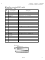
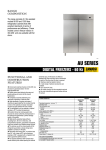
■21-pin Euro connector (SCART socket)
21-pin EURO-SCART 1 [AV1]
Pin
No.
Signal Designation
Matching Value
1
Audio Output Right
0.5V(rms), Impedance :<1kΩ (RF 54% MOD)
2
Audio Input Right
0.5V(rms), Impedance :>10kΩ
3
Audio Output!Left
0.5V(rms), Impedance :<1kΩ (RF 54% MOD)
4
Audio Earth
5
Blue Earth
6
Audio Input Left
0.5V(rms), Impedance :>10kΩ
7
Blue Input
0.7V(p-p) ±0.1V, Impedance :75Ω
8
Slow Switching
TV : 0-2V, AV 16/9 : 4.5-7V, AV 4/3 : 9.5-12V,
9
Green Earth
10
NC
11
Green Input
12
NC
13
Red Earth
14
Blanking Earth
15
Red Input
0.7V(p-p) ±0.1V, Impedance : 75Ω
16
Fast Switching
0-0.4V : Logic “0”, 1-3V : Logic “1”,
17
Video Out Earth
18
Video In Earth
19
Video Output
1V(p-p) ±3dB, Impedance :75Ω
20
Video Input
1V(p-p) ±3dB, Impedance :75Ω
21
Common Earth
Impedance :>10kΩ
0.7V(p-p) ±0.1V, Impedance : 75Ω
Impedance :75Ω
[Pin assignment]
No.51709
1-3
AV-28BD5EKI AV-28BD5EP AV-28BD5EE
AV-28BD5EKIS AV-28BD5EPS AV-28BD5EES
21-pin EURO-SCART 2 [AV2]
Pin
No.
Signal Designation
1
NC
2
Audio Intput!Right
3
NC
4
Audio Earth
5
Earth
6
Audio Input Left
7
NC
8
NC
9
NC
10
NC
11
NC
12
NC
13
Earth
14
Earth
15
Chroma Input
16
NC
17
Earth
18
Video In Earth
19
NC
20
Video Input, Y In.
21
Common Earth
Matching Value
0.5V(rms), Impedance :<10kΩ
0.5V(rms), Impedance :>10kΩ
±3dB for a luminance signal of 1V(p-p)
1V(p-p) ±3dB, Impedance :75Ω
[Pin assignment]
1-4
No.51709
AV-28BD5EKI AV-28BD5EP AV-28BD5EE
AV-28BD5EKIS AV-28BD5EPS AV-28BD5EES
SAFETY PRECAUTIONS
1. The design of this product contains special hardware, many circuits and components specially for safety purposes. For continued protection,
no changes should be made to the original design unless authorized in writing by the manufacturer. Replacement parts must be identical to
those used in the original circuits. Service should be performed by qualified personnel only.
2. Alterations of the design or circuitry of the products should not be made. Any design alterations or additions will void the manufacturer's
warranty and will further relieve the manufacturer of responsibility for personal injury or property damage resulting therefrom.
3. Many electrical and mechanical parts in the products have special safety-related characteristics. These characteristics are often not evident
from visual inspection nor can the protection afforded by them necessarily be obtained by using replacement components rated for higher
voltage, wattage, etc. Replacement parts which have these special safety characteristics are identified in the parts list of Service manual.
Electrical components having such features are identified by shading on the schematics and by ( !) on the parts list in Service
manual. The use of a substitute replacement which does not have the same safety characteristics as the recommended replacement part
shown in the parts list of Service manual may cause shock, fire, or other hazards.
4. Don't short between the LIVE side ground and ISOLATED (NEUTRAL) side ground or EARTH side ground when repairing.
Some model's power circuit is partly different in the GND. The difference of the GND is shown by the LIVE : (") side GND, the
ISOLATED(NEUTRAL) : (#) side GND and EARTH : ($) side GND. Don't short between the LIVE side GND and ISOLATED(NEUTRAL)
side GND or EARTH side GND and never measure with a measuring apparatus (oscilloscope etc.) the LIVE side GND and
ISOLATED(NEUTRAL) side GND or EARTH side GND at the same time.
If above note will not be kept, a fuse or any parts will be broken.
5. If any repair has been made to the chassis, it is recommended that the +B setting should be checked or adjusted (See +B ADJUSTMENT).
6. The high voltage applied to the picture tube must conform with that specified in Service manual. Excessive high voltage can cause an
increase in X-Ray emission, arcing and possible component damage, therefore operation under excessive high voltage conditions should
be kept to a minimum, or should be prevented. If severe arcing occurs, remove the AC power immediately and determine the cause by
visual inspection (incorrect installation, cracked or melted high voltage harness, poor soldering, etc.). To maintain the proper minimum level
of soft X-Ray emission, components in the high voltage circuitry including the picture tube must be the exact replacements or alternatives
approved by the manufacturer of the complete product.
7. Do not check high voltage by drawing an arc. Use a high voltage meter or a high voltage probe with a VTVM. Discharge the picture tube
before attempting meter connection, by connecting a clip lead to the ground frame and connecting the other end of the lead through a 10k"
2W resistor to the anode button.
8. When service is required, observe the original lead dress. Extra precaution should be given to assure correct lead dress in the high voltage
circuit area. Where a short circuit has occurred, those components that indicate evidence of overheating should be replaced. Always use
the manufacturer's replacement components.
No.51709
1-5
AV-28BD5EKI AV-28BD5EP AV-28BD5EE
AV-28BD5EKIS AV-28BD5EPS AV-28BD5EES
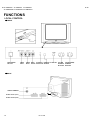
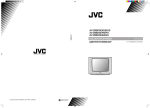
FUNCTIONS
LOCAL CONTROL
■FRONT
MAIN POWER
BUTTON
VIDEO
INPUT
AUDIO HEAD
STAND-BY REMOTE AV BUTTON
INPUT PHONE INDICATOR SENSOR
■BACK
AERIAL TERMINAL
SCART JACK 1 (AV1)
SCART JACK 2 (AV2)
1-6
No. 51709
VOLUME
DOWN/UP
BUTTONS
PR (PROGRAM)
DOWN/UP
BUTTONS
AV-28BD5EKI AV-28BD5EP AV-28BD5EE
AV-28BD5EKIS AV-28BD5EPS AV-28BD5EES
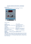
REMOTE CONTROL UNIT
TV mode
TELETEXT mode
48B00RMC71
[EP / EPS / EE / EES]
1. POWER
1. POWER
2. NUMBER 0-9 / NUMBER
2. NUMBER 0-9
3. P.MODE / OK
3. INDEX
4. AV
4. Not used
5. UP
5. UP
6. RIGHT
6. SUBPAGE
7. MENU
7. MENU
8. DOWN
8. DOWN
9. LEFT
9. HOLD
10. MUTING
10. MUTING
11. RECALL
11. REVEAL
12. SLEEP
12. SIZE
13. Not used
13. CANCEL
14. MOVE
14. GREEN
15. SKIP
15. RED
16. TV / TEXT
16. TV / TEXT
17. DELETE
17. YELLOW
18. MODE
19. VCR /
/ DVD switch
48B00RMC72
[EKI / EKIS]
20. VCR / DVD Control buttons
18. CYAN
19. VCR /
/ DVD switch
20. Not used
No. 51709
1-7
AV-28BD5EKI AV-28BD5EP AV-28BD5EE
AV-28BD5EKIS AV-28BD5EPS AV-28BD5EES
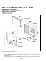
SPECIFIC SERVICE INSTRUCTIONS
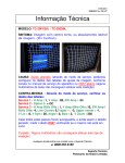
DISASSEMBLY PROCEDURE
Note : Before starting work, disconnect the power plug from the wall outlet.
HOW TO REMOVE THE REAR COVER
1. Remove the 10 screws marked [A].
2. Remove the rear cover backward.
CRT
CRT SOCKET PWB
A
REAR COVER
FBT
POWER SW
TUNER
MAIN PWB
SPEAKER
FRONT CABINET
MEMORY IC REPLACEMENT
1. Important :
After replacing the MEMORY IC (IC702) , certainly use the JVC REMOTE CONTROL UNIT to turn on the power.
2. If other maker (DAEWOO) REMOTE CONTROL UNIT is initially used, there is risk the TV set will no longer operate with the JVC
REMOTE CONTROL UNIT.
3. If the TV set is initialized to operate with the other maker (DAEWOO) REMOTE CONTROL UNIT, there is need to yet again replace the
MEMORY IC (IC702) .
1-8
No.51709
AV-28BD5EKI AV-28BD5EP AV-28BD5EE
AV-28BD5EKIS AV-28BD5EPS AV-28BD5EES
SERVICE ADJUSTMENTS
BEFORE ADJUSTMENT AND MAINTENANCE
1. Don't short any two soldering points or connect any component while TV set is power on.
2. Withdraw power plug before maintenance.
3. In order to ensure safety all components replaced should be identical. (For further details, refer to the component name and component No.
in PARTS LIST.)
4. Must be warm up the set for 30 minutes or more and degauss CRT thoroughly with demagnetizer coil before adjustment.
EQUIPMENT FOR ADJUSTMENT
1. Pattern Generator
2. Digital volt meter
3. Oscilloscope
4. Demagnetizer
5. Remote control unit
48B00RMC71
48B00RMC72
Remote Control unit
No.51709
1-9
AV-28BD5EKI AV-28BD5EP AV-28BD5EE
AV-28BD5EKIS AV-28BD5EPS AV-28BD5EES
BASIC OPERATION OF SERVICE MENU
How to ENTER and EXIT from SERVICE MODE
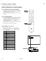
1. Press the MUTING KEY and RECALL KEY of the REMOTE
CONTOROL UNIT at the same time to display the service
MENU screen shown Fig. A and Fig. B.
2. When exiting from the SERVICE MODE, turn the power
switch off.
MUTING
How to set SERVICE MODE
1. Select the setting item you want to change with the P.(▲)/
P.(▼) key on the REMOTE CONTROL UNIT. (The item you
selected will be indicated by YELLOW on the display.)
2. When changing the set values, use the
-/
+KEY on the
REMOTE CONTROL UNIT.
3. When the setting has been completed, turn the power switch
off.
(The changed set values are stored in memory.)
RECALL
SERVICE MENU screen selection
● Press the P.(▲) / P.(▼) key ・・・・・・ select menu item.
(The letters of the selected items are displayed in yellow)
● Press the
No
-/
+ key ・・・・・・・・・ setting the value item.
Adjustment item
1
AGC
2
Black R
3
Black G
4
WP Red
5
WP Green
6
WP Blue
7
H Parall
8
H Bow
9
H Shift
10
V Slope
11
V Amp
12
V S Cor
13
V Shift
14
H Width
15
EW Parabo
16
Up Corner
17
Dw Corner
18
EW Trapez
19
Option
Fig. A
SERVICE
** Black R
screen
Setting value
SERVICE
** Black R
Fig. B
1-10
No.51709
menu item
AV-28BD5EKI AV-28BD5EP AV-28BD5EE
AV-28BD5EKIS AV-28BD5EPS AV-28BD5EES
ADJUSTMENTS
+B VOLTAGE CHECK
1. Receive the standard colour bar signal.
2. Connect digital voltmeter between + of B1 Line circuit and GND.
3. Confirm that voltage is DC 142V # 2.0V.
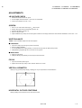
SCREEN
1. Set TV in AV mode without video signal ⇒ Black screen.
2. Set [WP Red], [WP Green] and [WP Blue] equal to “32”.
3. Set [Black R], [Black G] equal to “8”.
4. Set TV in normal I mode.
5. Adjust SCREEN VR (on FBT) such that the highest cathode cut-off voltage measured on CRT SOCKET PWB ASS’Y is DC 140V ± 5V.
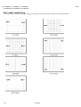
WHITE BALANCE
NOTE : Confirm SCREEN Adjustment has been adjusted.
■ LOW LIGHT
1.
2.
3.
4.
Input the 10-step gray scale signal. (include 10% Black)
Enter the SERVICE MODE.
Turn the SCREEN VR (on FBT) gradually, to where the 2nd gray bar(10% Black) faintly visible.
Adjust [Black B] and [Black R] not to the colours on the gray bar.
■ HIGH LIGHT
5. Apply the white signal.
6. Adjust [R DRIVE] and [G DRIVE] so that the picture becomes white.
FOCUS
1. Input the crosshatch pattern signal.
2. Adjust the FOCUS VR (on FBT) to have the best resolution on screen.
VERTICAL GEOMETRY
Adjust [V Amp], [V Shift] and [V Slope], [V Slope] [V S Cor] to compensate for vertical distortion.
HORIZONTAL PICTURE CENTERING
Adjust [H Shift] to have the picture in the center of the screen.
No.51709
1-11
AV-28BD5EKI AV-28BD5EP AV-28BD5EE
AV-28BD5EKIS AV-28BD5EPS AV-28BD5EES
EAST / WEST CORRECTION
Adjust [H. Parall], [H. Bow], [H. Widdth], [EW. Parabo], [Up Corner], [Dw Corner], [EW Trapez] to compensate for geometrical distortion.
1-12
No.51709