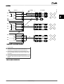
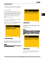
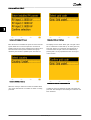
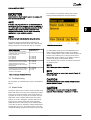
1
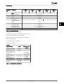
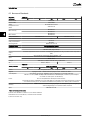
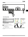
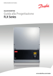
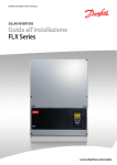
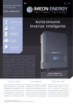
MAKING MODERN LIVING POSSIBLE
TLX
Installation Manual
Three-phase – 6k, 8k, 10k, 12.5k and 15k
SOLAR INVERTERS
Safety and Conformity
Safety and Conformity
General Safety
Safety
NOTE
All persons installing and servicing inverters must be:
•
Trained and experienced in general safety rules
for work on electrical equipment
•
Familiar with local requirements, rules and
regulations for the installation
Before installation
Check for damage to inverter and packaging. If in doubt,
contact the supplier before installing the inverter.
CAUTION
Installation
For optimum safety, follow the steps described in this
manual. Keep in mind that the inverter has two voltage
carrying sides; the PV input and the AC grid.
Safety Message Types
WARNING
Safety information important for human safety. Warnings
are used for indicating potentially hazardous situations
that can cause serious injury or death.
CAUTION
Cautions with symbol are used for indicating potentially
hazardous situations that can cause minor or moderate
injuries.
CAUTION
Cautions without symbol are used for indicating situations
that may result in equipment or property damage.
NOTE
Note is used for indicating highlighted information that
should be regarded with attention.
WARNING
Disconnecting the inverter
Before starting work on the inverter, switch off AC grid at
the mains switch and PV using the PV load switch. Ensure
that the device cannot be unintentionally reconnected. Use
a voltage tester to ensure that the unit is disconnected
and voltage free. The inverter can still be charged with
very high voltage at hazardous levels even when it is
disconnected from grid/mains and solar modules. Wait at
least 30 min. following disconnection from grid and PV
panels before proceeding.
CAUTION
Maintenance and modification
Only authorised personnel are allowed to repair or modify
the inverter. To ensure personal safety, only original spare
parts available from the supplier should be used. If nonoriginal spare parts are used, the compliance with CE
guidelines in respect of electrical safety, EMC and machine
safety is not guaranteed.
The temperature of the cooling racks and components
inside the inverter may exceed 70ºC. Observe the danger
of burn injury.
CAUTION
Functional safety parameters
Never change the parameters of the inverter without
authorisation from the local energy supply company and
instructions from Danfoss.
Unauthorised changes of functional safety parameters may
cause injury or accidents to people or inverter.
Additionally, it will lead to the cancellation of all inverter
operating approval certificates and Danfoss warranties.
Danfoss cannot be held responsible for such injuries or
accidents.
L00410309-09_02
Safety and Conformity
Hazards of PV Systems
DC voltages up to 1000 V are present in a PV system even
when the AC grid is disconnected. Faults or inappropriate
use may lead to electric arcing.
WARNING
Do not work on the inverter while disconnecting DC and
AC.
The short-circuit current of the photovoltaic panels is only
slightly higher than the maximum operating current and
depends on the level of solar irradiation.
PV Load Switch
The PV load switch (1) enables safe disconnection of DC
current.
Conformity
Go to the download area at www.danfoss.com/solar,
Approvals and Certifications, for information.
CE marking - This certifies the conformity of the
equipment with the regulations which apply in
accordance with the directives 2004/108/EC and
2006/95/EC.
Table 1.1
L00410309-09_02
Contents
Contents
1 Introduction
2
1.1.1 Installation Sequence
3
1.1.2 Overview of Inverter
4
2 Installation
5
2.1 Installation Dimensions and Patterns
5
2.2 Mounting the Inverter
8
2.3 Removing the Inverter
9
2.4 Opening and Closing the Inverter
9
2.5 AC Grid Connection
11
2.6 Parallel PV String Configuration
12
2.7 PV Connection
14
2.8 Auxiliary Input/Output
14
2.9 Autotest Procedure
14
3 Start-up and Check of Settings
3.1.1 Initial Setup
15
15
3.2 Troubleshooting
17
3.3 Master Mode
17
4 Technical Data
18
4.1 General Data
18
4.2 Norms and Standards
20
4.3 France UTE Requirements
21
4.4 Installation
21
4.5 Cable Requirements
22
4.6 Torque Specifications for Installation
25
4.7 Mains Circuit Specifications
26
4.8 Auxiliary Interface Specifications
27
4.9 RS-485 and Ethernet Connections
29
L00410309-09_02
1
Introduction
1 Introduction
1 1
This manual explains the installation and setup of the TLX
Series solar inverter, for the installation technician.
Illustration 1.1 Solar Inverter
The TLX Series inverter range comprises the variants:
TLX
TLX+
TLX Pro
TLX Pro+
TLX
TLX+
TLX Pro
TLX Pro+
Common features
Power
6 kVA - 15 kVA
Enclosure
IP54
PV connectors
MC4 connectors
User interface
Display
Service web interface
Languages
Web interface
DK, GB, DE, FR, ES, ITA, CZ, NL, GR
Table 1.1 Common Features
2
L00410309-09_02
Introduction
Product Label
11.
Verify the installation by comparing with the
auto-detection result in the display, as described
in 2.7 PV Connection.
12.
The inverter is now ready for operation.
1 1
Illustration 1.2 Product Label
The product label on the side of the inverter shows:
•
•
•
Inverter type
Important specifications
Serial number, see (1), for identification by
Danfoss
1.1.1 Installation Sequence
1.
Pay special attention to 1 Safety and Conformity.
2.
Install the inverter according to 2.1 Installation
Dimensions and Patterns and 2.2 Mounting the
Inverter.
3.
Open the inverter according to 2.4 Opening and
Closing the Inverter.
4.
Install AC according to 2.5 AC Grid Connection.
5.
Install PV.
6.
Install Auxiliary input according to 2.8 Auxiliary
Input/Output .
7.
Close the inverter according to 2.4 Opening and
Closing the Inverter.
8.
Turn on AC at the mains switch.
9.
Set language, time, date, installed PV power,
country and grid:
10.
-
For setup via the web interface, see the
TLX Series User Manual, Web Server Quick
Guide section.
-
For setup via the display, see 3 Start-up
and Check of Settings.
Turn on PV by turning the PV load switch on.
L00410309-09_02
3
Introduction
1.1.2 Overview of Inverter
1 1
Illustration 1.3 Overview of Danfoss TLX inverter
Live Parts
5.
Auxiliary interface: RS-485
1.
AC Connection Area
6.
2.
DC Connection Area
Auxiliary interface: Temperature, Irradiation,
Energy meter (SO)
3.
Terminal block for parallel connection
7.
Auxiliary interface: Ethernet
4.
Auxiliary output: Potential free relay
PELV (Safe to touch)
Other
8.
PV load switch
The TLX Pro and TLX Pro+ variants can also be configured via the web interface. For further information refer to the Web
Server User Manual.
4
L00410309-09_02
Installation
2 Installation
2.1 Installation Dimensions and Patterns
2 2
CAUTION
Follow these instructions carefully to ensure correct installation of the inverter.
Illustration 2.4 Ensure adequate air flow
NOTE
When choosing the installation place, ensure that all labels
are visible at all times. For details refer to 4 Technical Data.
Illustration 2.5 Mount on non-flammable surface
Illustration 2.1 Avoid constant stream of water
Illustration 2.6 Mount upright on vertical surface
Illustration 2.2 Avoid direct sunlight
Illustration 2.7 Prevent dust and ammonia gases
Illustration 2.3 Ensure adequate air flow
L00410309-09_02
5
Installation
2 2
Illustration 2.8 Safe Distances
Observe these distances when installing one or more
inverters. One-row mounting is recommended. Contact the
supplier for information on mounting in more rows.
6
L00410309-09_02
Installation
2 2
Illustration 2.9 Wall Plate
NOTE
Use of the wall plate delivered with the inverter is
mandatory.
Use screws that can safely carry the weight of the inverter.
The inverter must be aligned and it is important that the
inverter is accessible at the front to allow room for
servicing.
L00410309-09_02
7
2 2
Installation
2.2 Mounting the Inverter
Lift the inverter upwards (2) over the top of the mounting
plate until the inverter tilts towards the wall (3).
CAUTION
For safe handling of the inverter, two people must carry
the unit, or a suitable transport trolley must be used.
Safety boots must be worn.
Illustration 2.12 Place Inverter in Mounting Bracket
Place the lower part of the inverter against the mounting
bracket.
Illustration 2.10 Position the Inverter
Tilt the inverter as shown in the illustration and place the
top of the inverter against the mounting bracket. Use the
two guides (1) at the top plate to control the inverter
horizontally.
Illustration 2.11 Secure the inverter
Illustration 2.13 Fasten screws
Lower (4) the inverter and make sure that the hook of the
inverter base plate is placed in the lower part of the
8
L00410309-09_02
Installation
mounting bracket (5). Check that it is not possible to lift
the bottom of the inverter away from the mounting
bracket. (6) Fasten the screws on either side of the wall
plate to secure the inverter.
Use a TX 30 screwdriver to loosen the two front screws.
Turn the screwdriver until the screws pop up. Screws are
secured with a spring and cannot fall out.
2 2
2.3 Removing the Inverter
Loosen the locking screws on either side of the inverter.
Removal is performed in the reverse order of mounting.
With a firm grip at the lower end of the inverter, lift the
inverter approximately 20 mm vertically. Pull the inverter
slightly away from the wall. Push upwards at an angle until
the wall plate releases the inverter. Lift the inverter away
from the wall plate.
2.4 Opening and Closing the Inverter
WARNING
Remember to observe all ESD safety regulations. Any
electrostatic charge must be discharged by touching the
earthed housing before handling any electronic
component.
Illustration 2.15 Open the Inverter
Push the front cover upwards. When a slight resistance is
felt, give the front cover a tap on the bottom to snap it
into holding position. It is recommended to use the
holding position instead of dismounting the front cover
completely.
Illustration 2.14 Loosen Front Screws
L00410309-09_02
9
Installation
2 2
Illustration 2.16 Close the Inverter
To close the inverter, hold on to the lower end of the front
cover with one hand and give it a tap on the top until it
falls into place. Guide the front cover into place and fasten
the two front screws.
Illustration 2.17 Fasten Front Screws
CAUTION
The two front screws are the PE connection to the front
cover. Make sure that both screws are mounted and
fastened with the specified torque.
10
L00410309-09_02
Installation
2.5 AC Grid Connection
NOTE
150AA059.10
When choosing the installation place, ensure that all labels
are visible at all times. For details refer to 4 Technical Data.
L2
L3
Short-circuit bridge
L1, L2,
L3, N
3 mains (L1, L2, L3) and neutral (N) terminals
PE
Protective earth wire
Table 2.1 Legend to Illustration 2.19
10mm
Verify the inverter matches the grid-voltage.
2.
Release main circuit breaker and make
precautions to prevent reconnection.
3.
Open the front cover.
4.
Insert the cable through the AC gland to the
terminal blocks.
5.
The three mains wires (L1, L2, L3) and the Neutral
wire (N) are mandatory and must be connected
to the 4-pole terminal block with the respective
markings.
6.
The Protective Earth wire (PE) is mandatory and
must be connected directly to the chassis PE
terminal. Insert the wire and fasten the screw to
secure the wire.
7.
All wires must be properly fastened with the
correct torque. See 4.6 Torque Specifications for
Installation.
8.
Close the front cover, and remember to verify
that both front screws are applied with the
correct torque (6-8 Nm) to obtain PE connection.
9.
Close main circuit breaker.
N
PE
Illustration 2.18 AC Cable Wire Strip
The illustration shows the stripping of insulation of all 5
wires of the AC cable. The length of the PE wire must be
longer than the mains and neutral wires.
2 2
1.
140mm
16mm
L1
1
150AA002.11
CAUTION
For safety, check all wiring. Connecting a phase wire to the
neutral terminal may permanently damage the inverter. Do
not remove the short-circuit bridge at (1).
1
L1 L2 L3 N
PE
PE
Illustration 2.19 AC Connection Area
L00410309-09_02
11
Installation
2.6 Parallel PV String Configuration
2 2
1
12A
12A
12A
Cabling
Inverter
12A
20A
12A
20A
12A
20A
12A
20A
12A
20A
12A
20A
12A
20A
12A
20A
12A
20A
12A
12A
12A
1
12A
12A
12A
30A
1
12A
12A
12A
7A
7A
7A
7A
3
Illustration 2.20 Correct Parallel Connection
1
Parallel jumper
2
Parallel connection, 3 inputs
3
Parallel connection, 2 inputs
Table 2.2 Legend to Illustration 2.20
12
PV module
2
L00410309-09_02
150AA026.12
For parallel PV string configuration, always use the internal
parallel jumper, together with an external parallel coupling.
1
Inverter
12A
2
12A
20A
12A
20A
12A
20A
Cabling
7A
12A
12A
7A
12A
12A
2 2
7A
1
12A
7A
PV module
150AA027.12
Installation
3
12A
20A
12A
20A
12A
20A
30A
4
12A
12A
12A
12A
20A
12A
20A
12A
20A
30A
Illustration 2.21 Incorrect Parallel Connection
1
Parallel jumper
2
Parallel connection, 1 input. Current in first input is
exceeded, thus overloading cable and PV load switch.
3
Parallel connection missing. All PV power feeds into one
input, thus risking overload of PV connector, cable and PV
load switch.
4
Parallel jumper missing, thus risking overload of PV
connector, cable and PV load switch in the event of inverter
failure.
Table 2.3 Legend to Illustration 2.21
L00410309-09_02
13
2 2
Installation
CAUTION
2.7 PV Connection
WARNING
Do NOT connect PV to earth!
NOTE
Use a suitable voltmeter that can measure up to 1000 V
DC.
NOTE
PV Connection Procedure:
1.
First verify the polarity and maximum voltage of
the PV arrays by measuring the PV open-circuit
voltage. The PV open-circuit voltage must not
exceed 1000 V DC.
2.
Measure the DC voltage between the plusterminal of the PV array and Earth (or the green/
yellow PE cable). The voltage measured should
approximate zero. If the voltage is constant and
not zero there is an insulation failure somewhere
in the PV array. Locate and fix the failure before
continuing.
3.
Repeat this procedure for all arrays. It is allowed
to distribute the input power on the inputs
unevenly, presuming that:
•
•
4.
When unmated, the MC4 connectors are not IP54. Intrusion
of moisture may occur. In situations where the PV
connectors are not fitted, a seal cap must be mounted
(included in the scope of the delivery). All inverters with
MC4 connections are delivered with seal caps on inputs 2
and 3. During installation, the seal caps of those inputs
that are to be used are discarded.
The nom. PV power of the inverter is
not exceeded (6.2 / 8.2 / 10.3 / 12.9 /
15.5 kW).
The maximum short-circuit current of
the PV modules must not exceed 12 A
per input.
On the inverter turn the PV load switch into off
position. Connect the PV cables by means of MC4
connectors. Ensure correct polarity! The PV load
switch can now be switched on when required.
The inverter is protected against reversed polarity but it
will not generate power until the polarity is corrected. To
achieve optimum production, the open-circuit voltage
(STC) of the PV modules must be lower than the max.
input voltage of the inverter (see 4.1 General Data),
multiplied with a factor of 1.13. UOC, STC x 1.13 ≤ UMAX, inv.
2.8 Auxiliary Input/Output
The inverter has the following auxiliary input/output:
•
•
•
•
•
2 x RJ-45 for RS-485
2 x RJ-45 for Ethernet
1 x 8 pole terminal block for RS-485
1 x 10 pole terminal block for
-
PT1000 temperature sensor input x 3
-
Irradiation sensor input
-
Energy meter (S0) input
1 x 2 pole terminal block for relay outputs
Refer to the specifications for an overview of the
communication board and to the inverter user manual for
details regarding auxiliary input configuration via the
display.
2.9 Autotest Procedure
An automatic test of the inverter can be initialised by
activating the inverter autotest procedure:
•
Via the display, go to [Setup → Autotest] and
press OK.
•
Via the web interface, go to [Inverter level: Setup
→ Setup details → Autotest] and click on [Start →
Test].
The inverter autotest manual can be downloaded from
www.danfoss.com/solar.
Illustration 2.22 DC Connection Area
14
L00410309-09_02
Start-up and Check of Setti...
3 Start-up and Check of Settings
3.1.1 Initial Setup
The inverter is shipped with a predefined set of settings
for different grids. All grid specific limits are stored in the
inverter and must be selected at installation. It is always
possible to see the applied grid limits in the display. The
inverter accounts for daylight saving automatically.
After installation, check all cables and then close the
inverter.
Turn on AC at the mains switch.
3 3
Follow the setup wizard in the display, or, alternatively, set
up the inverter via the web interface.
When prompted by the display select language. This
selection has no influence on the operating parameters of
the inverter and is not a grid code selection.
Illustration 3.2 Set Time
Set time as prompted by the display. Press 'OK' to select
number. Press ‘▲’ to scroll up through the numbers. Select
by pressing 'OK'.
The clock is 24-hour format.
NOTE
It is very important to set the time and date accurately as
the inverter uses this for logging. If an incorrect time/date
is accidentally set, correct it immediately in the set date
and time menu [Setup → Inverter details → Set date and
time].
Illustration 3.1 Select Language
The language is set to English at initial start-up. To change
this setting press the OK button. Press ‘▼’ to scroll down
through the languages. Select language by pressing ‘OK’.
NOTE
To use the default language (English) simply press the 'OK'
button twice to select and accept.
Illustration 3.3 Set Date
Set date as prompted by the display. Press 'OK' to select.
Press ‘▲’ to scroll up through the numbers. Select by
pressing 'OK'.
L00410309-09_02
15
Start-up and Check of Setti...
3 3
Illustration 3.4 Installed PV Power
Illustration 3.6 Select Grid Code
Enter the amount of installed PV power for each of the PV
inputs. When two or more PV inputs are connected in
parallel, each PV input in the parallel group must be set to
the total amount of PV power installed to that group
divided by the number of parallel inputs. See Table 3.1.
The display will now show “Select grid”. The grid code is
set to “undefined” at initial start-up. To select grid code,
press 'OK'. Press ‘▼’ to scroll down through the list of
countries. Select the grid code for the installation by
pressing ‘OK’. It is very important that the correct grid
code is chosen.
Illustration 3.5 Select Country
Illustration 3.7 Confirm Grid Code Selection
Select the country in which the inverter is installed. Press
'▼' to scroll down the list of countries. To select a country,
press 'OK'.
16
Confirm the choice by selecting the grid code again and
press 'OK’. The settings for the chosen grid code have now
been activated.
L00410309-09_02
Start-up and Check of Setti...
CAUTION
Correct selection of grid code is essential to comply with
local and national standards.
Pro+ inverters in the network, enabling easy commissioning and data management of larger networks.
NOTE
If the two grid code selections do not match they will be
cancelled and it will be necessary to redo the selections. If
an incorrect grid code is accidentally accepted at the first
selection, simply accept the “Grid: Undefined” in the
confirm grid code screen. This will cancel the country
selection and a new selection is possible.
3 3
NOTE
If an incorrect grid code is selected twice, call service.
The inverter will start automatically if sufficient solar
radiation is available. The start-up will take a few minutes.
During this period, the inverter will carry out a self-test.
Actual Configuration
PV1, PV2 and PV3 are all set into
individual mode. The nominal PV
power installed are:
PV 1: 6000 W
PV 2: 6000 W
PV 3: 3000 W
PV1 and PV2 are set into parallel
mode and have a total of 10 kW PV
power installed. PV3 is set into
individual mode and has nominal 4
kW PV power.
PV1 and PV2 are set into parallel
mode and have a total of 11 kW PV
power installed. PV3 is set to ‘Off’
and has no PV installed.
“Installed PV power” to be
programmed
PV
PV
PV
PV
PV
PV
1:
2:
3:
1:
2:
3:
6000
6000
3000
5000
5000
4000
W
W
W
W
W
W
Illustration 3.8 Master Mode
To enable Master mode go to the Inverter details menu
[Setup→Inverter details→Master mode] and set Master
mode to Enabled. Ensure that no other master inverters are
present in the network prior to carrying out this action.
When Master mode is enabled, it is possible to initiate a
network scan [Setup→Inverter details→Master
mode→Network]. This will show all inverters connected to
the master inverter.
NOTE
Only 1 master per network is possible.
PV 1: 5500 W
PV 2: 5500 W
PV 3: 0 W
NOTE
The master inverter can operate in a network of up to 99
follower inverters.
Table 3.1 Examples of Installed PV Power
CAUTION
3.2 Troubleshooting
For information on Troubleshooting, see the TLX Reference
Manual.
All inverters connected to the internet through Ethernet
must be behind a firewall.
3.3 Master Mode
CAUTION
The TLX Pro and TLX Pro+ inverters include a Master mode
feature that allows one inverter to be appointed as master
inverter. From the web interface of the master inverter, it
is possible to access any inverter in the network from one
single point using a standard web browser. The master
inverter can act as a datalogger, collecting data from all
inverters in the network. These data can be displayed
graphically from the web interface of the master inverter,
or the data can also be uploaded to external webportals or
exported directly to a PC. The master inverter is also able
to replicate settings and data to the other TLX Pro and TLX
At first login to the web ,server change the default
password. Plant level: [Setup → Web server → Admin].
L00410309-09_02
17
4 4
Technical Data
4 Technical Data
4.1 General Data
Nomenclat
ure1)
Parameter
TLX Series
6k
TLX Series
8k
TLX Series
10k
TLX Series
12.5k
TLX Series
15k
|S|
Rated apparent power
Pac,r
6000 VA
8000 VA
10000 VA
12500 VA
15000 VA
Rated active power*)
6000 W
8000 W
10000 W
12500 W
15000 W
5700 W
7600 W
9500 W
11875 W
14370 W
5400 W
7200 W
9000 W
11250 W
13500 W
0-3.6 kVAr
0-4.8 kVAr
0-6.0 kVAr
0-7.5 kVAr
0-9.0 kVAr
AC
Active power at cos(phi) =
0.95**)
Active power at cos(phi) =
0.90**)
Reactive power range
Vac,r
Iacmax
Rated grid voltage (range)
3P + N + PE - 230 V / 400 V (± 20%)
Rated current AC
3 x 8.7 A
3 x 11.6 A
3 x 14.5 A
3 x 18.1 A
3 x 21.7 A
Max. current AC
3 x 9.0 A
3 x 11.9 A
3 x 14.9 A
3 x 18.7 A
3 x 22.4 A
AC current distortion (THD
%)
cosphiac,r
< 4%
< 5%
Power factor at 100% load
> 0.99
Controlled power
factor range
0.8 over-excited
0.8 under-excited
Power loss, Connecting
10 W
mode
Night-time power loss (off
grid)
fr
<5W
Grid frequency (range)
50 Hz (± 5 Hz)
DC
Pmpptmax
Maximum PV input power
per MPPT
ΣP
Max./nom. converted PV
input power,
total
mpptmax
Vdc,r
Nominal rated voltage DC
Vmppmin -
MPP voltage - nominal
Vmppmax
power
8000 W
6200 W
8250 W
10300 W
12900 W
15500 W
358-800 V
430-800 V
700 V
2)
260-800 V
345-800 V
MPP efficiency, static
430-800 V
99.9%
MPP efficiency, dynamic
99.7%
Vdcmax
Max. DC voltage
1000 V
Vdcstart
Turn on voltage DC
250 V
Vdcmin
Turn off voltage DC
Idcmax
Max. current DC
2 x 12 A
3 x 12 A
Max. short circuit current
DC at STC
2 x 12 A
3 x 12 A
250 V
Min. on grid power
20 W
Efficiency
Max. efficiency
18
97.8%
97.9%
L00410309-09_02
98.0%
Technical Data
Nomenclat
ure1)
Parameter
Euro efficiency, V at
TLX Series
6k
TLX Series
8k
TLX Series
10k
TLX Series
12.5k
TLX Series
15k
96.5%
97.0%
97.0%
97.3%
97.4%
dc,r
Other
Dimensions (H,W,D)
700 x 525 x 250 mm
Mounting
Wall bracket
Weight
35 kg
Acoustic noise level
56 dB(A)
MPP trackers
2
3
Operation temperature
range
-25..60 °C
Nom. temperature range
-25..45 °C
Storage temperature
-25..60 °C
Overload operation
Change of operating point
Active power
control3)
4 4
Included
Reactive power control
TLX+ and TLX Pro+
Table 4.1 General Specifications
1) According to FprEN 50524 where relevant.
2) At identical input voltages. At unequal input voltages, Vmppmin can
be as low as 250 V depending on total input power.
3) Remotely controlled via CLX monitoring and grid management
product or third-party device.
*) At rated grid voltage (Vac,r), Cos(phi) = 1.
**) At rated grid voltage (Vac,r).
Parameter
TLX Series
Functional Safety
Passive
Safety (protective class)
Class I
PELV on the communication and control card
Class II
Islanding detection - loss
of mains
Active AC disconnection
Three-phase
monitoring ROCOF
Voltage magnitude
Included
Frequency
Included
Insulation resistance
Included
RCMU - Type B
Indirect contact
protection
Included
Yes (class I,
grounded)
Table 4.2 Functional Safety Specifications
L00410309-09_02
19
4 4
Technical Data
4.2 Norms and Standards
Normative
References
TLX Series
6k
8k
10k
Directive LVD
2006/95/EC
Directive EMC
2004/108/EC
Safety
12.5k
15k
IEC 62109-1/IEC 62109-2
Integrated PV load
switch
VDE 0100-712
EN 61000-6-1
EMC immunity
EN 61000-6-2
EN 61000-6-3
EMC emission
EN 61000-6-4
Utility interference
EN 61000-3-2/-3
EN 61000-3-11/-12
CE
Yes
IEC 61727
Utility characteristics
EN 50160
S0 Energy Meter
EN62053-31 Annex D
Functional Safety
For transformerless inverter
Germany
VDE 0126-1-1/A11)
VDE AR-N 4105 (August 2011)2)
Technical requirements for the connection of independent generation to the grid, Public Power Corporation
(PPC).
Greece
-
Italy
CEI 0-21:2012-06, Terna Guida Tecnica Allegato A.702)
RD1699 (2011)
Spain
RD661 (2007)
Portugal
VDE 0126-1-1, ISO/IEC Guide 67: 2004 - System No.5
UK
-
G59/2-1, G83/1-1
G59/2-1
TLX Series
Ancillary Services
TLX+ and TLX Pro+
6k
8k
10k
12.5k
Austria
TOR – Hauptabschnitt D4, TOR – Hauptabschnitt D2
Belgium
Synergrid C10/11 – Revisie 2012-06, Synergrid C10/17- revisie 8 mei 2009
Czech Republic
France
Czech Energy Act (Act No. 458/2000), Article 24, Paragraph 10 part I,II,III rev09 2009
UTE NF C 15-712-1 (UNION TECHNIQUE DE L'ELECTRICITE, GUIDE PRATIQUE, Installations photovoltaïques
raccordées au réseau public de distribution).
NF C 15-100 (Installations électriques à basse tension).
Journal Officiel, Décret n°2008-386 du 23 avril 2008 relatif aux prescriptions techniques générales de conception
et de fonctionnement pour le raccordement d'installations de production aux réseaux publics d'électricité.
Germany
-
BDEW- Technische Richtlinie Erzeugungsanlagen am Mittelspannungsnetz Ausgabe, Juni
2008 und Ergänzungen von 01/2009, 07/2010, 02/20112)
Spain
REE BOE núm. 254
Table 4.3 Norms and Standards
1) Deviant from VDE 0126-1-1 section 4.7.1, the isolation resistance
measurement limit is set to 200 kΩ, in accordance with authorities.
2) TLX+ and TLX Pro+ only.
20
15k
L00410309-09_02
Technical Data
4.3 France UTE Requirements
NOTE
In France, observe the UTE C 15-712-1 and NF C 15-100
requirements.
Parameter
Condition
Specification
Wall Plate
Hole diameter
30 x 9 mm
Alignment
Perpendicular ± 5° all
angles
Table 4.5 Wall Plate Specifications
For installation in France, apply warning label to front of
inverter.
4 4
Illustration 4.1 Position of Warning Label
4.4 Installation
Parameter
Specification
Temperature
−25 °C - +60 °C (>45 °C derating)
Environmental class
according to IEC
IEC60721-3-3
3K6/3B3/3S3/3M2
Air quality - general
ISA S71.04-1985
Level G2 (at 75% RH)
Air quality - coastal,
heavy industrial and
agricultural zones
Must be measured and classified acc. to
ISA S71.04-1985
Vibration
1G
Ingress protection
class
54
Max. operating
altitude
3000 m above sea level.
PELV protection is effective up to 2000
m above sea level only.
Installation
Avoid constant stream of water.
Avoid direct sunlight.
Ensure adequate air flow.
Mount on non-flammable surface.
Mount upright on vertical surface.
Prevent dust and ammonia gases.
Table 4.4 Conditions for Installation
L00410309-09_02
21
4.5 Cable Requirements
Cable
Condition
Specification
AC
Outer diameter
Max. recommended cable length
TLX Series
6k, 8k and 10k
5 wire cable
Copper
18-25 mm
21 m
34 m
52 m
87 m
28 m
41 m
69 m
34 m
59 m
2.5 mm2
4 mm2
6 mm2
10 mm2
4 mm2
6 mm2
10 mm2
6 mm2
10 mm2
Max. recommended cable length
TLX Series
12.5k
Max. recommended cable length
TLX Series
15k
DC
Max. 1000 V, 12 A
Cable length
< 200 m*
4 mm2 - 4.8 Ω /km
Cable length
>200-300 m*
6 mm2 - 3.4 Ω /km
Mating connector
Multi-contact
PV-ADSP4./PV-ADBP4.
* The distance between inverter and PV array and back, plus the cumulative length of PV array cabling.
Table 4.6 Cable Requirements
NOTE
Avoid power loss in cables greater than 1% of nominal
inverter rating.
[%]
2
150AA044.11
4 4
Technical Data
2
2.5 mm
2
1.5
4 mm
2
6 mm
2
10 mm
1
0.5
0
0
20
40
Illustration 4.2 TLX Series 6k Cable Losses [%] versus Cable Length [m]
22
L00410309-09_02
60
80
[m]
[%]
2
150AA045.11
Technical Data
2
2.5 mm
1.5
4 mm 2
6 mm 2
10 mm 2
1
0.5
0
0
4 4
20
40
60
80
[m]
60
80
[m]
[%]
2
1.5
150AA046.11
Illustration 4.3 TLX Series 8k Cable Losses [%] versus Cable Length [m]
2.5 mm2
2
4 mm
2
6 mm
2
10 mm
1
0.5
0
0
20
40
Illustration 4.4 TLX Series 10k Cable Losses [%] versus Cable Length [m]
L00410309-09_02
23
Technical Data
150AA047.11
[%]
2
2
4 mm
2
6 mm
1.5
2
10 mm
1
0.5
4 4
0
0
20
40
60
80
[m]
60
80
[m]
Illustration 4.5 TLX Series 12.5k Cable Losses [%] versus Cable Length [m]
150AA048.11
[%]
2
2
4 mm
2
6 mm
1.5
2
10 mm
1
0.5
0
0
20
40
Illustration 4.6 TLX Series 15k Cable Losses [%] versus Cable Length [m]
Consider also the following when choosing cable type and
cross-sectional area:
24
-
Ambient temperature
-
Layout type (inside wall, under ground, free air
etc.)
-
UV resistance
L00410309-09_02
Technical Data
4.6 Torque Specifications for Installation
4 4
150AA007.11
Illustration 4.7 Overview of Inverter with Torque Indications, 1-3
6
4
5
7
Illustration 4.8 Overview of Inverter with Torque Indications, 4-7
1
2
3
4
5
6
7
Parameter
Tool
Tightening Torque
Terminal blocks (large)
Terminal blocks (small)
PE
M16
M25
Front screw
Locking screw
Straight slot 1.0 x 5.5 mm
Straight slot 1.0 x 5.5 mm
Straight slot 1.0 x 5.5 mm
SW 19 mm
SW 30 mm
TX 30
TX 30
Min. 1.2 Nm
0.5 Nm
2.2 Nm
2-3 Nm
2-3 Nm
6-8 Nm
5 Nm
Table 4.7 Legend to Illustration 4.7 and Illustration 4.8, Nm Specifications
L00410309-09_02
25
4 4
Technical Data
4.7 Mains Circuit Specifications
TLX Series
6k
8k
10k
12.5k
15k
Maximum inverter
current, Iacmax.
9.0 A
11.9 A
14.9 A
18.7 A
22.4 A
Recommended
blow fuse type gL/
gG
13 A
16 A
20 A
20 A
25 A
Recommended
automatic fuse type
B
16 A
20 A
20 A
25 A
32 A
Table 4.8 Mains Circuit Specifications
26
L00410309-09_02
Technical Data
4.8 Auxiliary Interface Specifications
Parameter
Parameter Details
Specification
Cable jacket diameter (⌀)
2 x 5-7 mm
Cable type
Shielded Twisted Pair (STP) (Cat 5e)2)
Serial Communication
Common cable specification
RJ-45 (2 pcs.) connectors
Terminal block
RS-485
Cable Characteristic Impedance
100 Ω – 120 Ω
Max. cable length
1000 m
Wire gauge
24-26 AWG (depending on mating metallic RJ-45
plug)
Cable shield termination
Via metallic RJ-45 plug
Maximum wire gauge
2.5 mm2
Cable shield termination
Via EMC cable clamp
Max. number of inverter nodes
634)
Galvanic interface insulation
Yes, 500 Vrms
Direct contact protection
Double/Reinforced insulation
Short-circuit protection
Yes
Yes
Communication
Star and daisy chain
Ethernet
Common cable
Max. cable length between inverters
100 m (total network length: unlimited)
Specification
Max. number of inverters
1001)
Cable type
Shielded Twisted Pair (STP) (Cat 5e)2)
Temperature sensor input
Cable specification
Sensor specification
Direct contact protection
3 x PT1000
4-8 mm
Cable type
Shielded Single Pair - 2-wire
Cable shield termination
Via EMC cable clamp
Maximum wire gauge
2.5 mm2
Maximum resistance per wire
10 Ω
Maximum cable length
30 m
Nominal resistance/temperature coefficient
3.85 Ω/oC
Measurement range
-20 oC - +100 oC
Measurement accuracy
±3%
Double/Reinforced insulation
Yes
Yes
Irradiation sensor input
Sensor Specification
Direct contact protection
x1
Cable jacket diameter (⌀)
4-8 mm
Cable type
Shielded Single Pair - Number of wires depend on
the sensor type used
Cable shield termination
Via EMC cable clamp
Maximum wire gauge
2.5 mm2
Maximum resistance per wire
10 Ω
Maximum cable length
30 m
Sensor type
Passive
Measurement accuracy
±5% (150 mV sensor output voltage)
Output voltage of sensor
0-150 mV
Max. output impedance (sensor)
500 Ω
Input impedance (electronics)
22 kΩ
Double/Reinforced insulation
Yes
Short-circuit protection
Energy meter input
3)
Cable jacket diameter (⌀)
Short-circuit protection
Cable specification
4 4
Yes
S0 input
x1
L00410309-09_02
27
4 4
Technical Data
Parameter
Parameter Details
Specification
Cable specification
Cable jacket diameter (⌀)
4-8 mm
Sensor Input Specification
Direct contact protection
Cable type
Shielded Single Pair - 2-wire
Cable shield termination
Via EMC cable clamp
Maximum wire gauge
2.5 mm2
Maximum cable length
30 m
Sensor input class
Class A
Nominal output current
12 mA for an 800 Ω load
Maximum short-circuit output current
24.5 mA
Open-circuit output voltage
+12 VDC
Maximum pulse frequency
16.7 Hz
Double/Reinforced insulation
Yes
Short-circuit protection
Yes
Table 4.9 Auxiliary Interface Specifications
1)
A maximum of 100 inverters can be connected in 1 network. If
GSM modem is used for portal upload, the number of inverters in a
network is limited to 50.
2)
For underground use, outdoor burial type cable is recommended
for both Ethernet and RS-485.
3)
Third input is used for compensation of the irradiation sensor.
4)
The number of inverters to be connected in the RS-485 network
depends on which peripheral device is connected.
CAUTION
To ensure fulfilment of IP enclosure rating, correctly
mounted cable glands are essential for all peripheral
cables.
Parameter
Condition
Specification
Potential free
contact
Relay output
x1
Rating AC
250 V AC, 6.4 A, 1600 W
Rating DC
24 V DC, 6.4 A, 153 W
Maximum wire
gauge
2.5 mm2
Overvoltage
category
Class III
Modem
GSM
Table 4.10 Auxiliary Input Specifications
CAUTION
To ensure EMC compliance, shielded cables must be
applied for sensor inputs and RS-485 communication.
Unshielded cables may be applied for alarm outputs.
Other auxiliary cables must pass through the designated
EMC cable clamps to establish mechanical fixing and in
case of shielded cable termination to the shielding device.
28
L00410309-09_02
1
150AA058.11
Technical Data
RS485
2 x RJ45
Ethernet
2 x RJ45
2
+/
3
5
4
+/
+/
7
6
+/
+/
4 4
L
N
Illustration 4.9 Communication Board
1
8-pole terminal blocks
2
PT1000/module temp.
3
PT1000/ambient temp.
4
PT1000/irradiation sensor temp.
5
Irradiation sensor
6
S0/Energy meter
7
Relay 1
Table 4.11 Legend to Illustration 4.9
4.9 RS-485 and Ethernet Connections
RS-485
Terminate the RS-485 communication bus at both ends.
To terminate the RS-485 bus:
•
•
Connect Bias H to RX/TX B
Connect Bias L to RX/TX A
Illustration 4.10 RS-485 Communication Detail - Cat 5 T-568A
The RS-485 address of the inverter is unique, and defined
at the factory.
L00410309-09_02
29
2
3
4
5
6
7
8
1
2
3
4
5
6
7
8
150AA019.10
1
150AA019.10
Technical Data
4 4
Illustration 4.11 RJ-45 Pinout Detail for RS-485
Illustration 4.12 RJ-45 Pinout Detail for Ethernet
1
GND
Colour Standard
2
GND
Pinout Ethernet
3
RX/TX A (-)
Cat 5
T-568A
Cat 5
T-568B
4
BIAS L
1
RX+
Green/white
Orange/white
5
BIAS H
2
RX
Green
Orange
6
RX/TX B (+)
3
TX+
Orange/white
Green/white
7
Not connected
4
Blue
Blue
8
Not connected
5
Blue/white
Blue/white
Orange
Green
7
Brown/white
Brown/white
8
Brown
Brown
6
Table 4.12 Legend to Illustration 4.11
Bold=Compulsory, Cat5 cable contains all 8 wires
For Ethernet: 10Base-TX and 100Base-TX auto cross over
Ethernet
Ethernet connection is available for TLX Pro and TLX Pro+
variants only.
TX-
Table 4.13 Legend to Illustration 4.12
CAUTION
TLX Pro and TLX Pro+ inverters connected to the internet
through Ethernet must be behind a firewall.
CAUTION
At first login to the web server, change the default
password. Plant level: [Setup → Web server → Admin].
30
L00410309-09_02
Danfoss Solar Inverters A/S
Ulsnaes 1
DK-6300 Graasten
Denmark
Tel: +45 7488 1300
Fax: +45 7488 1301
E-mail: [email protected]
www.danfoss.com/solar
Danfoss can accept no responsibility for possible errors in catalogues, brochures and other printed material. Danfoss reserves the right to alter its products without notice. This also applies to products
already on order provided that such alterations can be made without subsequential changes being necessary in specifications already agreed.
All trademarks in this material are property of the respective companies. Danfoss and the Danfoss logotype are trademarks of Danfoss A/S. All rights reserved.
Rev. date 2012-11-25 Lit. No. L00410309-09_02