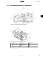
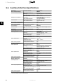
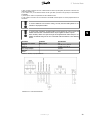
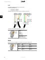
1
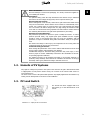
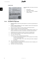
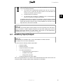
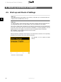
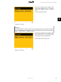
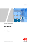
MAKING MODERN LIVING POSSIBLE
TripleLynx CN
Installation Manual
Three-phase – 10, 12.5 and 15 kW
SOLAR INVERTERS
Contents
Contents
1. Safety and Conformity
2
Important Safety Information
2
Hazards of PV Systems
3
PV Load Switch
3
Conformity
4
2. Introduction
5
Introduction
5
Installation Sequence
6
Overview of Inverter
7
3. Installation
8
Installation Dimensions and Patterns
8
Mounting the Inverter
10
Removing the Inverter
12
Opening and Closing the Inverter
12
AC Grid Connection
14
PV Connection
16
Auxiliary Input/Output
17
4. Start-up and Check of Settings
18
Start-up and Check of Settings
18
Troubleshooting
21
Master Mode
21
5. Technical Data
23
Technical Data
23
Norms and Standards
24
Installation
24
Cable Requirements
25
Torque Specifications for Installation
27
Auxiliary Interface Specifications
28
Network Topology
31
L00410580-01_02
1
1. Safety and Conformity
1
1. Safety and Conformity
1.1. Important Safety Information
All persons installing and servicing inverters must be:
•
Trained and experienced in general safety rules for work on electrical equipment
•
Familiar with local requirements, rules and regulations for the installation
Safety information important for human safety. Violation of warnings may result in
injury to persons or death.
Information important for the protection of property. Violation of this type of information may cause damage and loss of property.
Note:
Useful additional information or “Tips and Tricks” on specific subjects.
Read this before installing, operating or maintaining the inverter.
2
L00410580-01_02
1. Safety and Conformity
Before installation:
Check for damage to inverter and packaging. If in doubt, contact the supplier before installing the inverter.
Installation:
For optimum safety, follow the steps described in this manual. Keep in mind that
the inverter has two voltage carrying sides; the PV input and the AC grid.
Disconnecting the inverter:
Before starting work on the inverter, switch off AC grid at the mains switch and PV
using the PV load switch. Ensure that the device cannot be unintentionally reconnected. Use a voltage tester to ensure that the unit is disconnected and voltage
free. The inverter can still be charged with very high voltage at hazardous levels
even when it is disconnected from grid/mains and solar modules. Wait at least 30
min. following disconnection from grid and PV panels before proceeding.
Maintenance and modification:
Only authorised personnel are allowed to repair or modify the inverter. To ensure
optimum personal safety, only original spare parts available from the supplier
should be used. If non-original spare parts are used, the compliance with CE
guidelines in respect of electrical safety, EMC and machine safety is not guaranteed.
Also observe the danger of burn injury. The temperature of the cooling racks and
components inside the inverter may exceed 70ºC.
Functional safety parameters:
Never change the parameters of the inverter without authorisation from the local
energy supply company and instructions from Danfoss.
Unauthorised changes of functional safety parameters may cause injury or accidents to people or inverter. Additionally it will lead to the cancellation of all inverter operating approval certificates.
The Danfoss inverters are all designed according to the German VDE0126-1-1
(February 2006) standard, which includes an insulation test between PV array(s)
and Earth, and a type B, RCMU according to DIN VDE 0100-712.
1
1.2. Hazards of PV Systems
Very high DC voltages are present in the system even when the AC grid is disconnected. Faults
or inappropriate use may lead to electric arcing. Do not work on the inverter while it has current connected to it.
The short-circuit current of the photovoltaic panels is only slightly higher than the maximum operating current and depends on the level of solar irradiation.
1.3. PV Load Switch
The inverter has been equipped with a PV
load switch (1) for safe disconnection of DC
current.
Illustration 1.1: TripleLynx CN PV Load Switch
L00410580-01_02
3
1. Safety and Conformity
1
1.4. Conformity
For approvals and certification information, go to the download area at
•
www.danfoss.com/solar, Approvals and Certifications
•
www.danfoss.cn/solar
CGC marking - This certifies the conformity of the equipment with the regulations which apply in accordance with China General Certification Center,
CGC/GF004:2011.
4
L00410580-01_02
2. Introduction
2. Introduction
2
2.1. Introduction
This manual explains the installation and setup of the TripleLynx CN solar inverter, for the installation technician.
The inverter display and Web Server are available in Chinese language only. In the manual,
English texts appearing in the screenshots and menus are shown for guidance only.
Illustration 2.1: TripleLynx CN 8 kW, 10 kW, 12.5 kW, 15 kW
The
TLX
TLX
TLX
TLX
TripleLynx CN inverter series comprises:
CN
CN+
CN Pro
CN Pro+
Common features of the TripleLynx CN variants:
•
Output rating of 8 kW, 10 kW, 12.5 kW or 15 kW
•
IP 54 enclosure
•
PV load switch
•
MC4 connectors
•
Manual access via the local display, for inverter configuration
Additionally, the TLX CN Pro and TLX CN Pro+ variants provide:
•
Local and web server access for inverter configuration
•
Ancillary service functionalities. Refer to the chapter Ancillary Services for details.
L00410580-01_02
5
2. Introduction
Product Label
The product label on the side of the inverter
shows:
2
•
Inverter type
•
Important specifications
•
Serial number, see (1), for identification by Danfoss
Illustration 2.2: Product Label
2.1.1. Installation Sequence
6
1.
Read the installation manual. Pay special attention to the section Important Safety Information.
2.
Install the inverter according to the section Installation Dimensions and Patterns and
the section Mounting the Inverter.
3.
Open the inverter according to the section Opening and Closing the Inverter.
4.
Install AC according to the section AC Grid Connection.
5.
Install PV. Remember to use the terminal block to establish parallel connection (if required), as described in the section PV Connection. The inverter has auto-detection.
6.
Install Auxiliary input according to the section Connection of Peripheral Units.
7.
Close the inverter according to the section Opening and Closing the Inverter.
8.
Turn on AC at the mains switch.
9.
Set language, time, date, installed PV power and country:
-
For setup via the integrated Web Server, see the TripleLynx CN User Manual,
Web Server Quick Guide section
-
For setup via the display, see the section Start-up and Check of Settings in
this manual.
10.
Turn on PV by turning the PV load switch on.
11.
Verify the installation by comparing with the auto-detection result in the display, as described in the section PV Connection.
12.
The inverter is now ready for operation.
L00410580-01_02
2. Introduction
2.1.2. Overview of Inverter
2
Illustration 2.3: Overview of Danfoss TLX CN inverter
Live Part
1.
AC Connection Area
2.
DC Connection Area
3.
Terminal block for parallel connection
4.
Auxiliary output: Potential free relay
PELV (Safe to touch)
5.
Auxiliary interface: RS485
6.
Auxiliary interface: Temperature, Irradiation, Energy meter (SO)
7.
Auxiliary interface: Ethernet
Other
8.
DC-switch
The TLX CN Pro and TLX CN Pro+ variants can also be configured via the Web Server. For further information refer to the Web Server User Manual.
L00410580-01_02
7
3. Installation
3. Installation
3.1. Installation Dimensions and Patterns
3
Note:
When choosing the installation place, ensure that all labels are visible at all times.
For details refer to the section Specifications.
Avoid constant stream of water.
Avoid direct sunlight.
Ensure adequate air flow.
Ensure adequate air flow.
Mount on non-flammable surface.
Mount upright on vertical surface.
Prevent dust and ammonia gases.
8
L00410580-01_02
3. Installation
3
Illustration 3.1: Safe Distances
Observe these distances when installing one or more inverters. One row mounting is recommended. Contact the supplier for information on mounting in more rows.
Illustration 3.2: Wall Plate
Note:
Use of the wall plate delivered with the inverter is mandatory.
Use screws that can safely carry the weight of the inverter. The inverter must be aligned and it
is important that the inverter is accessible at the front to allow room for servicing.
L00410580-01_02
9
3. Installation
3.2. Mounting the Inverter
For safe handling of the inverter, two people must carry the unit, or a suitable
transport trolley must be used. Safety boots must be worn.
3
Tilt the inverter as shown in the illustration
and place the top of the inverter against the
mounting bracket. Use the two guides (1) at
the top plate to control the inverter horizontally.
Illustration 3.3: Position the Inverter
Lift the inverter upwards (2) over the top of
the mounting plate until the inverter tilts towards the wall (3).
Illustration 3.4: Secure the inverter
10
L00410580-01_02
3. Installation
Place the lower part of the inverter against
the mounting bracket.
3
Illustration 3.5: Place Inverter in Mounting
Bracket
Lower (4) the inverter and make sure that
the hook of the inverter base plate is placed
in the lower part of the mounting bracket
(5). Check that it is not possible to lift the
bottom of the inverter away from the mounting bracket.
(6) Fasten the screws on either side of the
wall plate to secure the inverter.
Illustration 3.6: Fasten screws
L00410580-01_02
11
3. Installation
3.3. Removing the Inverter
Loosen the locking screws on either side of the inverter.
Removal is performed in the reverse order of mounting. With a firm grip at the lower end of the
inverter, lift the inverter approximately 20 mm vertically. Pull the inverter slightly away from the
wall. Push upwards at an angle until the wall plate releases the inverter. Lift the inverter away
from the wall plate.
3
3.4. Opening and Closing the Inverter
Remember to observe all ESD safety regulations. Any electrostatic charge must be
discharged by touching the grounded housing before handling any electronic component.
Use a TX 30 screwdriver to loosen the two
front screws. Turn the screwdriver until the
screws pop up. Screws are secured with a
spring and cannot fall out.
Illustration 3.7: Loosen Front Screws
12
L00410580-01_02
3. Installation
Push the front cover upwards. When a slight
resistance is felt, give the front cover a tap
on the bottom to snap it into holding position. It is recommended to use the holding
position instead of dismounting the front
cover completely.
3
Illustration 3.8: Open the Inverter
To close the inverter, hold on to the lower
end of the front cover with one hand and
give it a tap on the top until it falls into
place. Guide the front cover into place and
fasten the two front screws.
Illustration 3.9: Close the Inverter
L00410580-01_02
13
3. Installation
3
Illustration 3.10: Fasten Front Screws and Ensure Proper PE Connection
The two front screws are the PE connection to the front cover. Make sure that
both screws are mounted and fastened with the specified torque.
3.5. AC Grid Connection
Note:
When choosing the installation place, ensure that all labels are visible at all times.
For details refer to the section Specifications.
14
L00410580-01_02
3. Installation
3
Illustration 3.11: AC Cable Wire Strip
Legend
1 Blue cable - Neutral
2 Yellow/green cable - Earth
The illustration shows the stripping of insulation of all 5 wires of the AC cable. The length of the
PE wire must be longer than the mains and neutral wires.
Illustration 3.12: AC Connection Area
1.
Verify the inverter matches the grid-voltage.
2.
Release main circuit breaker and make precautions to prevent reconnection.
3.
Open the front cover.
4.
Insert the cable through the AC gland to the terminal blocks.
5.
The three mains wires (L1, L2, L3) and the Neutral wire (N) are mandatory and must
be connected to the 4-pole terminal block with the respective markings.
6.
The Protective Earth wire (PE) is mandatory and must be connected directly to the
chassis PE terminal. Insert the wire and fasten the screw to secure the wire.
7.
All wires must be properly fastened with the correct torque. See the section Technical
Data, Torque Specifications for Installation.
L00410580-01_02
15
3. Installation
8.
Close the front cover, and remember to verify that both front screws are applied with
the correct torque to obtain PE connection.
9.
Close main circuit breaker.
For safety, check all wiring. Connecting a phase wire to the neutral terminal may
permanently damage the inverter. Do not remove the short circuit bridge at (1).
3
3.6. PV Connection
Note:
When choosing the installation place, ensure that all labels are visible at all times.
For details refer to the section Specifications.
Do NOT connect PV to earth!
Use a suitable voltmeter that can measure up to 1000 V DC.
1.
First verify the polarity and maximum voltage of the PV arrays by measuring the PV
open circuit voltage.The PV open circuit voltage must not exceed 1000 V DC.
2.
Measure the DC voltage between the plus-terminal of the PV array and Earth (or the
green/yellow PE cable). The voltage measured should approximate zero. If the voltage
is constant and not zero there is an insulation failure somewhere in the PV array.
3.
Locate and fix the failure before continuing.
4.
Repeat this procedure for all arrays. It is allowed to distribute the input power on the
inputs unevenly, presuming that:
•
The nom. PV power of the inverter is not exceeded (8.2 / 10.3 / 12.9 / 15.5
kW).
•
The individual input is not exceedingly loaded, and not more than 6000 W.
•
The maximum short circuit current of the PV modules at STC (Standard Test
Conditions) must not exceed 12 A per input.
On the inverter turn the PV load switch into
off position. Connect the PV cables by means
of MC4 connectors. Ensure correct polarity!
The PV load switch can now be switched on
when required.
Illustration 3.13: DC Connection Area
16
L00410580-01_02
3. Installation
When unmated the MC4 connectors are not IP54. The intrusion of moisture may
occur in the following situations:
1.
The inverter runs in Master/Slave operation and only one or two PV inputs are in use. In this case, the other inputs are not connected to PV
and they are therefore open to intrusion.
2.
Not all PV inputs are connected.
3.
PV connectors are not fitted; for example in case of disconnection of
parts of a PV plant over a longer period of time.
3
In situations where the PV connectors are not fitted, a seal cap must be mounted
(included in the scope of the delivery). All inverters with MC4 connections are delivered with seal caps on inputs 2 and 3. During installation, the seal caps of those
inputs that are to be used are discarded.
Note:
The inverter is protected against reversed polarity but it will not generate power until the polarity is corrected. To achieve optimum production, the open circuit voltage (STC) of the PV
modules must be lower than the max. input voltage of the inverter (see the specifications),
multiplied with a factor of 1.13. UOC, STC x 1.13 ≤ UMAX, inv
3.7. Auxiliary Input/Output
Note:
When choosing the installation place, ensure that all labels are visible at all times.
For details refer to the section Specifications.
The inverter has the following auxiliary input/output:
•
2 x RJ45 for RS485
•
2 x RJ45 for Ethernet
•
1 x 8 pole terminal block for RS485
•
1 x 10 pole terminal block for
•
-
PT1000 temperature sensor input x 3
-
Irradiation sensor input
-
Energy meter (S0) input
1 x 2 pole terminal block for relay outputs
Refer to the specifications for an overview of the communication board and to the inverter user
manual for details regarding auxiliary input configuration via the display.
L00410580-01_02
17
4. Start-up and Check of Settings
4. Start-up and Check of Settings
4.1. Start-up and Check of Settings
Note:
Due to the advanced functionalities of the inverter, it may take up to 10 seconds before the
display becomes available after power up.
4
Note:
For the TLX CN Pro version the first start-up and check of settings can also be performed via
the integrated Web Server. For further details, refer to the Web Server User Manual.
The inverter is shipped with a predefined set of settings for different grids. All grid specific limits
are stored in the inverter and must be selected at installation. It is always possible to see the
applied grid limits in the display. The inverter accounts for daylight saving automatically.
After installation, check all cables and then close the inverter.
Turn on AC at the mains switch.
When prompted by the display select language. This selection has no influence on the operating
parameters of the inverter and is not a grid code selection.
The language is set to Chinese at initial
start-up.
Illustration 4.1: Select Language
18
L00410580-01_02
4. Start-up and Check of Settings
Set time as prompted by the display. Press
'OK' to select number. Press ‘ ▲ ’ to scroll up
through the numbers. Select by pressing
'OK'.
The clock is 24-hour format.
4
Illustration 4.2: Set Time
Note:
It is very important to set the time and date accurately as the inverter uses this for logging.
If a wrong time/date is accidentally set, correct it immediately in the set date and time menu
[Setup → Inverter details → Set date and time].
Set date as prompted by the display. Press
'OK' to select. Press ‘ ▲ ’ to scroll up through
the numbers. Select by pressing 'OK'.
Chinese date format: yyyy-mm-dd.
Illustration 4.3: Set Date
L00410580-01_02
19
4. Start-up and Check of Settings
Enter the amount of installed PV power for
each of the PV inputs. When two or more PV
inputs are connected in parallel, each PV input in the parallel group must be set to the
total amount of PV power installed to that
group divided by the number of parallel inputs. See the table below for examples of installed PV power.
4
Illustration 4.4: Installed PV Power
The display will now show “Select grid”. The
grid code is set to “undefined” at initial startup. To select grid code, press 'OK'. Press ‘
▼ ’ to scroll down through the list of countries. Select the grid code for the installation
by pressing ‘OK’. To meet medium-voltage
grid requirements select a grid code ending
in MV. It is very important that the correct
grid code is chosen.
Illustration 4.5: Select Grid Code
Confirm the choice by selecting the grid code
again and press 'OK’. The settings for the
chosen grid code have now been activated.
Illustration 4.6: Confirm Grid Code Selection
Correct selection of grid code is essential to comply with local and national standards.
20
L00410580-01_02
4. Start-up and Check of Settings
Note:
If the two grid code selections do not match they will be cancelled and it will be necessary to
redo the selections. If an incorrect grid code is accidentally accepted at the first selection,
simply accept the “Grid: Undefined” in the confirm grid code screen. This will cancel the
country selection and a new selection is possible. If an incorrect grid code is selected twice,
call service.
The inverter will start automatically if sufficient solar radiation is available. The start-up will take
a few minutes. During this period, the inverter will carry out a self-test.
4
“Installed PV power” to be
programmed
Actual Configuration
PV1, PV2 and PV3 are all set into individual mode. The nominal PV power
installed are:
PV 1: 6000 W
PV 2: 6000 W
PV 3: 3000 W
PV1 and PV2 are set into parallel mode and have a total of 10 kW PV
power installed. PV3 is set into individual mode and has nominal 4 kW PV
power.
PV1 and PV2 are set into parallel mode and have a total of 11 kW PV
power installed. PV3 is set to ‘Off’ and has no PV installed.
PV
PV
PV
PV
PV
PV
PV
PV
PV
1:
2:
3:
1:
2:
3:
1:
2:
3:
6000
6000
3000
5000
5000
4000
5500
5500
0W
W
W
W
W
W
W
W
W
Table 4.1: Examples of Installed PV Power
4.2. Troubleshooting
For information on Troubleshooting, please see the TLX CN Reference Manual.
4.3. Master Mode
The TLX CN Pro and TLX CN Pro+ inverters include a Master Mode feature that allows one inverter to be appointed as Master Inverter. From the web interface of the master inverter, it is
possible to access any inverter in the network from one single point using a standard web
browser. The Master Inverter can act as a datalogger, collecting data from all inverters in the
network. These data can be displayed graphically from the web server of the Master Inverter,
or the data can also be uploaded to external webportals or exported directly to a PC. The Master Inverter is also able to replicate settings and data to the other TLX CN Pro and TLX CN Pro+
inverters in the network, enabling easy commissioning and data management of larger networks. Replication can be performed once, prior to defining the grid code in follower inverters.
L00410580-01_02
21
4. Start-up and Check of Settings
To enable Master mode go to the Inverter
details menu [Setup → Inverter details →
Master mode] and set Master mode to Enabled. Ensure that no other master inverters
are present in the network prior to carrying
out this action.
When Master mode is enabled, it is possible
to initiate a network scan [Setup → Inverter
details → Master mode → Network]. This will
show all inverters connected to the master
inverter.
4
Illustration 4.7: Master Mode
22
L00410580-01_02
5. Technical Data
5. Technical Data
5.1. Technical Data
Nomenclature 1)
Pac,r
Vac,r
Iacmax
cosphiac,r
fr
Vdc,r
Vmppmin Vmppmax
Vdcmax
Vdcstart
Vdcmin
Idcmax
Parameter
AC
Nom. power AC
Reactive power range
AC voltage range (P-N)
Nominal current AC
Max. current AC
AC current distortion (THD
%)
Power factor at 100 % load
Controlled power
factor range
“Connecting” power loss
Night-time power loss (off
grid)
Grid frequency
DC
Nominal power DC
Max. recommended PV
power at STC 2)
Nominal voltage DC
MPP voltage - nominal
power 3)
MPP efficiency
Max. DC voltage
Turn on voltage DC
Turn off voltage DC
Max. current DC
Max. short circuit current
DC at STC
Min. on grid power
Efficiency
Max. efficiency
Euro efficiency, V at dc,r
Other
Dimensions (L,W,H)
Mounting recommendation
Weight
Acoustic noise level4
MPP trackers
Operation temperature
range
Nom. temperature range
Storage temperature
Overload operation
Overvoltage category AC
Overvoltage category DC
PLA5)
Reactive power
Functional Safety
Safety (protective class)
PELV on the communication
and control card
Islanding detection - loss of
mains
Voltage magnitude
Frequency
DC content of AC current
Insulation resistance
RCMU - Type B
Indirect contact protection
Short circuit protection
TripleLynx CN
8 kW
TripleLynx CN
10 kW
TripleLynx CN
12.5 kW
TripleLynx CN
15 kW
8000 W
0-4.8 kVAr
3 x 230 V ± 20 %
3 x 12 A
3 x 12 A
<4%
10000 W
0-6.0 kVAr
3 x 230 V ± 20 %
3 x 15 A
3 x 15 A
<5%
12500 W
0-7.5 kVAr
3 x 230 V ± 20 %
3 x 19 A
3 x 19 A
<5%
15000 W
0-9.0 kVAr
3 x 230 V ± 20 %
3 x 22 A
3 x 22 A
<5%
> 0.98
0.8 over-excited
0.8 under-excited
10 W
<5W
> 0.99
0.8 over-excited
0.8 under-excited
10 W
<5W
> 0.99
0.8 over-excited
0.8 under-excited
10 W
<5W
> 0.99
0.8 over-excited
0.8 under-excited
10 W
<5W
50 ± 5 Hz
50 ± 5 Hz
50 ± 5 Hz
50 ± 5 Hz
8250 W
9500 Wp
10300 W
11800 Wp
12900 W
14700 Wp
15500 W
17700 Wp
700 V
345-800 V
700 V
430-800 V
700 V
358-800 V
700 V
430-800 V
99.9 %
1000 V
250 V
250 V
2 x 12 A
2 x 12 A
99.9 %
1000 V
250 V
250 V
2 x 12 A
2 x 12 A
99.9 %
1000 V
250 V
250 V
3 x 12 A
3 x 12 A
99.9 %
1000 V
250 V
250 V
3 x 12 A
3 x 12 A
20 W
20 W
20 W
20 W
97.9 %
97.0 %
98 %
97.0 %
98 %
97.3 %
98 %
97.4 %
700 x 525 x 250
mm
Wall bracket
35 kg
56 dB(A)
2
-25..60 °C
700 x 525 x 250
mm
Wall bracket
35 kg
56 dB(A)
2
-25..60 °C
700 x 525 x 250
mm
Wall bracket
35 kg
56 dB(A)
3
-25..60 °C
700 x 525 x 250
mm
Wall bracket
35 kg
56 dB(A)
3
-25..60 °C
-25..45 °C
-25..60 °C
Change of operating point
Class III
Class II
Included
TLX CN+ and TLX
CN Pro+
-25..45 °C
-25..60 °C
Change of operating point
Class III
Class II
Included
TLX CN+ and TLX
CN Pro+
-25..45 °C
-25..60 °C
Change of operating point
Class III
Class II
Included
TLX CN+ and TLX
CN Pro+
-25..45 °C
-25..60 °C
Change of operating point
Class III
Class II
Included
TLX CN+ and TLX
CN Pro+
Class I
Class II
Class I
Class II
Class I
Class II
Class I
Class II
Three-phase monitoring (ROCOF)
Included
Included
Included
Included
Included
Yes (class I, grounded)
Yes
Three-phase monitoring (ROCOF)
Included
Included
Included
Included
Included
Yes (class I, grounded)
Yes
Three-phase monitoring (ROCOF)
Included
Included
Included
Included
Included
Yes (class I, grounded)
Yes
Three-phase monitoring (ROCOF)
Included
Included
Included
Included
Included
Yes (class I, grounded)
Yes
5
Table 5.1: Specifications
L00410580-01_02
23
5. Technical Data
1)
2)
3)
4)
5)
According to FprEN 50524.
For fixed systems with semi-optimal conditions.
At identical input voltages. At unequal input voltages, Vmppmin can be as low as 250 V depending on total input power.
SPL (Sound Pressure Level) at 1.5m.
Grid Management Box (TLX CN Pro and TLX CN Pro+) or third-party product.
5.2. Norms and Standards
Refer to Chapter 1, section Conformity for details.
5.3. Installation
Parameter
Temperature
Environmental class according to IEC
Specification
−25 °C - +60 °C (>45 °C derating)
IEC60721-3-3
3K6/3B3/3S3/3M2
Air quality
ISA S71.04-1985
Level G2 (at 75 % RH)
Coastal, heavy industrial and farmer areas Must be measured and classified acc. to ISA S71.04-1985
Vibration
1G
Ingress protection class
54
Max. operating altitude
3000 m above sea level.
PELV protection is effective up to 2000 m above sea level only.
Installation
Avoid constant stream of water.
Avoid direct sunlight.
Ensure adequate air flow.
Mount on non-flammable surface.
Mount upright on vertical surface.
Prevent dust and ammonia gases.
5
Table 5.2: Conditions for Installation
Parameter
Wall Plate
Condition
Hole diameter
Alignment
Specification
30 x 9 mm
Perpendicular ± 5° all angles
Table 5.3: Wall Plate Specifications
24
L00410580-01_02
5. Technical Data
5.4. Cable Requirements
Cable
AC
Outer diameter
Insulation strip
Max. recommended cable length
TripleLynx CN
8 kW and 10 kW
Max. recommended cable length
TripleLynx CN
12.5 kW
Condition
5 wire cable
All 5 wires
2.5 mm2
4 mm2
6 mm2
10 mm2
4 mm2
6 mm2
10 mm2
6 mm2
10 mm2
Specification
Copper
18-25 mm
16 mm
21 m
34 m
52 m
87 m
28 m
41 m
69 m
34 m
59 m
Max. recommended cable length
TripleLynx CN
15 kW
PE Cable diameter
at least
as phase cables
DC
Max. 1000 V, 12 A
Cable length
< 200 m*
4 mm2 - 4.8 Ω /km
Cable length
>200-300 m*
6 mm2 - 3.4 Ω /km
Mating connector
Multi-contact
PV-ADSP4./PV-ADBP4.
* The distance between inverter and PV array and back, plus the summarised length of the cables used for
PV array installation.
5
Table 5.4: Cable Requirements
Note:
Avoid power loss in cables of more than 1 % of nominal inverter rating.
Illustration 5.1: TripleLynx CN 8 kW Cable Losses [%] versus Cable Length [m]
L00410580-01_02
25
5. Technical Data
5
Illustration 5.2: TripleLynx CN 10 kW Cable Losses [%] versus Cable Length [m]
Illustration 5.3: TripleLynx CN 12.5 kW Cable Losses [%] versus Cable Length [m]
Illustration 5.4: TripleLynx CN 15 kW Cable Losses [%] versus Cable Length [m]
Consider also the following when choosing cable type and cross-sectional area:
26
-
Ambient temperature
-
Layout type (inside wall, under ground, free air etc.)
-
UV resistance
L00410580-01_02
5. Technical Data
5.5. Torque Specifications for Installation
5
Illustration 5.5: Overview of Inverter with Torque Indications, 1-3
Illustration 5.6: Overview of Inverter with Torque Indications, 4-7
1
2
3
4
5
6
7
Parameter
Terminal blocks (large)
Terminal blocks (small)
PE
M16
M25
Front screw
Locking screw
Screwdriver
Straight slot 1.0 x 5.5 mm
Straight slot 1.0 x 5.5 mm
Straight slot 1.0 x 5.5 mm
SW 19 mm
SW 30 mm
TX 30
TX 30
Tightening Torque
Min. 1.2 Nm
0.5 Nm
2.2 Nm
2-3 Nm
2-3 Nm
6-8 Nm
5 Nm
Table 5.5: Nm Specifications
L00410580-01_02
27
5. Technical Data
5.6. Auxiliary Interface Specifications
Parameter
Serial Communication
Common cable specification
RJ45 (2 pcs.) connectors
Terminal block
Parameter Details
Cable jacket diameter (⌀)
Cable type
Cable Characteristic Impedance
Max. cable length
Wire gauge
Cable shield termination
Maximum wire gauge
Cable shield termination
Max. number of inverter nodes
Galvanic interface insulation
Direct contact protection
Double/Reinforced insulation
Short circuit protection
Communication
Star and daisy chain
Common cable
Max. cable length between inverters
Specification
Max. number of inverters
Cable type
Temperature sensor input
Cable specification
Cable jacket diameter (⌀)
Cable type
Cable shield termination
Maximum wire gauge
Maximum resistance per wire
Maximum cable length
Sensor specification
Nominal resistance/temperature
coefficient
Measurement range
Measurement accuracy
Direct contact protection
Double/Reinforced insulation
Short circuit protection
Irradiation sensor input
Cable specification
Cable jacket diameter (⌀)
Cable type
5
Sensor Specification
Direct contact protection
Short circuit protection
Energy meter input
Cable specification
Sensor Input Specification
Direct contact protection
Short circuit protection
-20 oC - +100 oC
±3 %
Yes
Yes
x1
4-8 mm
Shielded Single Pair - Number of wires
depend on the sensor type used
Cable shield termination
Via EMC cable clamp
Maximum wire gauge
2.5 mm2
Maximum resistance per wire
10 Ω
Maximum cable length
30 m
Sensor type
Passive
Measurement accuracy
±5 % (150 mV sensor output voltage)
Output voltage of sensor
0-150 mV
Max. output impedance (sensor) 500 Ω
Input impedance (electronics)
22 kΩ
Double/Reinforced insulation
Yes
Yes
S0 input
x1
4-8 mm
Cable jacket diameter (⌀)
Cable type
Shielded Single Pair - 2-wire
Cable shield termination
Via EMC cable clamp
Maximum wire gauge
2.5 mm2
Maximum cable length
30 m
Sensor input class
Class A
Nominal output current
12 mA for an 800 Ω load
Maximum short circuit output cur- 24.5 mA
rent
Open circuit output voltage
+12 VDC
Maximum pulse frequency
16.7 Hz
Double/Reinforced insulation
Yes
Yes
Table 5.6: Auxiliary Interface Specifications
28
Specification
RS485
2 x 5-7 mm
Shielded Twisted Pair (STP) (Cat 5e)2)
100 Ω – 120 Ω
1000 m
24-26 AWG (depending on mating
metallic RJ45 plug)
Via metallic RJ45 plug
2.5 mm2
Via EMC cable clamp
634)
Yes, 500 Vrms
Yes
Yes
Ethernet
100 m (total network length: unlimited)
1001)
Shielded Twisted Pair (STP) (Cat 5e)2)
3 x PT1000 3)
4-8 mm
Shielded Single Pair - 2-wire
Via EMC cable clamp
2.5 mm2
10 Ω
30 m
3.85 Ω/oC
L00410580-01_02
5. Technical Data
1) Max. number of inverters are 100. If GSM modem is used for portal upload, the amount of inverters in a
network is limited to 50.
2) For outdoor use, we recommend outdoor burial type cable (if buried in the ground) for both Ethernet
and RS485.
3) Third input is used for compensation of the irradiation sensor.
4) The number of inverters to be connected in the RS485 network depend on which peripheral device is
connected.
To ensure fulfilment of IP enclosure rating, correctly mounted cable glands are essential for all peripheral cables.
To ensure EMC compliance, shielded cables must be applied for sensor inputs and
RS485 communication. Unshielded cables may be applied for alarm outputs.
Other auxiliary cables must pass through the designated EMC cable clamps to establish mechanical fixing and in case of shielded cable termination to the shielding
device.
Parameter
Potential free contact
Rating AC
Rating DC
Maximum wire gauge
Over voltage category
Optional
Modem
Condition
Relay output
5
Specification
x1
250 VAC, 6.4 A, 1600 W
24 VDC, 6.4 A, 153 W
2.5 mm2
Class III
GSM
Table 5.7: Auxiliary Input Specifications
Illustration 5.7: Communication Board
L00410580-01_02
29
5. Technical Data
RS485
Terminate the RS485 communication bus at both ends.
To terminate the RS485 bus:
•
Connect Bias L to RX/TX B
•
Connect Bias H to RX/TX A
The RS485 address of the inverter is unique, and defined at the factory.
5
Illustration 5.8: RS485 Communication Detail - Cat 5 T-568A
Pinout RS485
1. GND
2. GND
3. RX/TX A (-)
4. BIAS L
5. BIAS H
6. RX/TX B (+)
7. Not connected
8. Not connected
Bold = Compulsory, Cat5 cable
contains all 8 wires
For Ethernet: 10Base-TX and
100Base-TX auto cross over
Table 5.8: RJ45 Pinout Detail for RS485
Ethernet
Ethernet connection is available for TLX CN Pro and TLX CN Pro+ variants only.
Pinout
Ethernet
1.
2.
3.
4.
5.
6.
7.
8.
RX+
RX
TX+
TX-
Colour Standard
Cat 5
T-568A
Green/white
Green
Orange/white
Blue
Blue/white
Orange
Brown/white
Brown
Table 5.9: RJ45 Pinout Detail for Ethernet
30
L00410580-01_02
Cat 5
T-568B
Orange/white
Orange
Green/white
Blue
Blue/white
Green
Brown/white
Brown
5. Technical Data
5.6.1. Network Topology
The inverter has two Ethernet RJ45 connectors enabling the connection of several inverters in a
line topology as an alternative to the typical star topology. The two ports are similar and may
be used interchangeably. For RS485, only linear daisy chain connections can be used.
Note:
Ring topology is not allowed.
5
Illustration 5.9: Network Topology
1
2
3
(4)
Linear Daisy Chain
Star Topology
Ring Topology (not allowed)
(Ethernet Switch)
Note:
The two network types cannot be mixed. The inverters can only be connected in networks
which are either solely RS485 or solely Ethernet.
Note:
Ethernet connection is recommended for faster communication.
RS485 connection is required when a web logger or data logger is connected to the inverter.
L00410580-01_02
31
Danfoss Solar Inverters A/S
Ulsnaes 1
DK-6300 Graasten
Denmark
Tel: +45 7488 1300
Fax: +45 7488 1301
E-mail: [email protected]
www.solar-inverters.danfoss.com
Danfoss (Shanghai) Automatic Controls Co., Ltd.
20th, Floor, Block C, Hi-Tech Building 900 Yi Shan Road
Shanghai 200233, P.R.China
Tel: +86 (21) 61513000
Fax: +86 (21) 61513100
www.danfoss.com.cn
丹佛斯(上海)自动控制有限公司
上海市宜山路900号科技大楼C楼20层
电话:+86 (21) 61513000
传真:+86 (21) 61513100
www.danfoss.com.cn
Rev. date 2011-11-16 Lit. No. L00410580-01_02