1
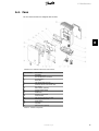
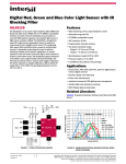
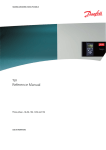
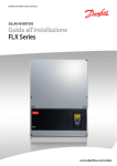
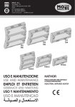
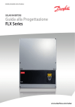
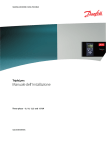
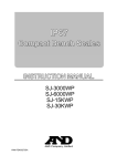
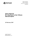
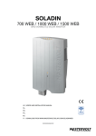
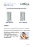
Contents
Contents
1. Supplement to Manual Set
2
2. Grid Codes
3
3. Functionality Supporting EEG2012 (Germany)
5
4. TLX Series 6k
9
5. Parallel PV String Configuration
14
6. Miscellaneous
16
L00410591-04_02
1
1. Supplement to Manual Set
1
1. Supplement to Manual Set
1.1. Introduction
The information in the enclosed manual set applies, with the addition of this supplementary information.
Refer to the download area at www.danfoss.com/solar for the newest manuals.
2
L00410591-04_02
2. Grid Codes
2. Grid Codes
2
2.1. Grid Codes
Select grid codes as follows:
Germany
New installations:
•
“Germany_MV” = for installations on the medium-voltage grid (medium-voltage guideline).
•
“Germany_LV1” = for installations up to and including 13.8 kVA connected to the lowvoltage grid (AR-N 4105).
•
“Germany_LV2” = for installations above 13.8 kVA connected to the low-voltage grid
(AR-N 4105).
•
”Germany_LV3” = for installations connected to the low-voltage grid (AR-N4105) with
pre-configured Power factor = 1
Existing installations:
•
“VDE_0126_1_1_A1” = Exchange units in installations where “Germany” is the selected grid code.
Italy
•
“Italy” = for installations connected to the low-voltage grid without a transformer.
•
“Italy-plant” = for installations connected to the low-voltage grid or medium-voltage
grid with a transformer.
•
“Italy 6 kW” = for installations up to 6 kW connected to the low-voltage grid without
an external disconnection device (SPI).
Denmark
New installations:
•
“Denmark_LV1” = for installations up to and including 11 kVA connected to the lowvoltage grid (TF 3.2.1 / AR-N 4105).
•
“Denmark_LV2” = for installations above 11 kVA connected to the low-voltage grid (TF
3.2.1 / AR-N 4105).
•
“Denmark_LV3” = for installations connected to the low-voltage grid (AR-N 4105) with
preconfigured Power factor = 1
•
“EN 50438-DK” = for installations with TLX / TLX Pro (TF 3.2.1 / EN 50438-DK)
Existing installations:
•
“EN 50438-DK” = Exchange units in installations (before 01.01.2012) where “Denmark” is the selected grid code or for TLX / TLX Pro (TF 3.2.1 / EN 50438-DK).
L00410591-04_02
3
2. Grid Codes
2.2. Reactive Power
Standard reactive power settings are configured with the grid code. Changes to a standard grid
code will generate the grid code 'custom'.
2
PF(P)
The inverter will generate a variable level of reactive power depending on the output power.
The relationship between reactive power and active power is entered as a setpoint curve. The
setpoint curve can consist of up to 9 points with the reactive power in the range from: 0.8 under-excited to 0.8 over-excited.
150AA032.10
PF
0.80
0.85
0.90
0.95
1.00
P/Pnom
50
100
0.95
0.90
0.85
0.80
Illustration 2.1: Example of Default Setpoint Curve for Germany LV: Installations less than or equal to 13.8
kVA
For some grid codes, the setpoint curve behaviour is only activated over a certain grid voltage
level.
Italy
To ensure that sufficient current is always available to supply the required reactive power, the
inverter must allocate spare capacity. In these cases, the inverter active power output is limited
to: [name plate rating] x [cos(φ) required]
Example: 6 kVA x 0.9 = 5.4 kW (see AC power rating table)
To override this value, set reactive power settings via the web interface, at
Plant level: [Setup → Grid Management]
To remove this allocation of spare capacity, disable reactive power.
4
L00410591-04_02
3. Functionality Supporting EEG2012 (Germany)
3. Functionality Supporting EEG2012 (Germany)
3.1. Introduction
3
For installation in Germany, for inverters of any rating, follow this instruction carefully.
This inverter complies with the requirements of Erneuerbare-Energien-Gesetz (EEG2012). The
EEG2012 redefines how PV installations are designed in terms of output power and grid connection:
•
The requirement for remote-controlled power reduction (known as Power Level Adjustment) is extended from installations exceeding 100 kW capacity only, to apply to all
installations.
•
Alternatively for installations of capacity up to and including 30kWp, a 70% rule can be
applied.
3.2. Configuration of Power Level Adjustment
Power level adjustment (PLA) is an existing feature in the inverter which is now used for smaller
installations. For further information about PLA, refer to the Reference Manual and the Web
Server User Manual.
3.3. Configuration of 70% Rule
The EEG2012 states that the power at the point of common coupling (PCC) must be limited to
transfer of max. 70% of installed nominal PV module power [kWp]. This limit is referred to as
“70% of installed PV power”. Thus it is possible to take self-consumed power into account. It is
important that the self-consumption can be guaranteed. This means that the real value of selfconsumption must under no circumstances fall below the value used in the calculation.
Limit the power at PCC to 70% of the installed nominal PV module power [kWp]
Note:
When an incorrect value of “70% of installed PV power” is entered, serious consequences
can result. In the event that the 70% limit is exceeded, the DNO can demand disconnection
of the installation from grid.
3.3.1. Example of Calculation
This is an example of how to calculate “Absolute value”, used in the section How to Configure a
Limit for the Output Power.
Data:
•
12 kWp installed power
•
Inverter rating 10 kW
•
1 kW guaranteed self-consumption
L00410591-04_02
5
3. Functionality Supporting EEG2012 (Germany)
Calculation of ”70% of installed PV power”:
•
Absolute value
= (Installed peak PV power x 0.7)[kW] + Self-consumption [kW]
= (12 kWp x 0.7 kW/kWp) + 1 kW
= 8.75 kW+1 kW
3
= 9.75 kW
= 9750 W
•
The entry for “Absolute value” is 9750.
3.3.2. How to Configure a Limit for the Output Power (Inverter
Level)
Note:
Access at security level 1 or higher is required, in order to configure PLA and output power
limits.
Configuration via display interface:
1.
In the inverter display, go to [Setup → Grid management → Output power]
2.
Follow the steps in the section Configuration via Display Interface (Inverter Level).
3.
To replicate to the other inverters in the network, go to [Setup → Service → Replicate].
Configuration via the web server or service interface (TLX Pro and TLX Pro+ only):
1.
Go to [Inverter → Setup → Grid management → Output power]
2.
Follow the steps in the section Configuration via the Web Server or Service Interface
(Inverter Level).
3.
To replicate to the other inverters in the network, go to [Inverter → Setup → Service →
Replicate]
3.3.3. Configuration via Display Interface (Inverter Level)
There are four methods to limit the output power of the inverter:
1.
Limit output power by external input (default setting).
2.
Absolute value [W].
3.
Percentage based on total installed PV power *(peak PV power connected to the inverter).
4.
Percentage based on nominal AC output power **(kW – nominal AC output power of
the inverter).
To set an absolute value:
1.
In the inverter display, go to [Setup → Grid management → Output power → Lim type].
2.
Choose “Absolute value”.
3.
Choose “Output power limit” and enter the applicable output limit of the inverter (for
example 7000 W).
4.
Click “Save”.
The inverter output power will now be limited to an absolute value. For example: 7 kW.
6
L00410591-04_02
3. Functionality Supporting EEG2012 (Germany)
To set a percentage based on total installed PV power:
1.
In the inverter display, go to [Setup → Grid management → Output power → Lim type].
2.
Choose “Pct based on PV” .
3.
Choose “Output power limit” and enter the applicable output limit of the inverter (for
example 70%).
4.
Click “Save”.
3
The inverter output power will now be limited to a percentage value of the total installed PV
power.
For example: When the installed power is 18 kWp, and the output power of the inverter is limited to 70%, then output power = 18x0.7 = 12.6 kW.
To set a percentage based on nominal AC output power:
1.
In the inverter display, go to [Setup → Grid management → Output power → Lim type].
2.
Choose “Pct based on ACP” in the Lim. Type menu.
3.
Choose “Output power limit” and enter the applicable output limit of the inverter (for
example 70%).
4.
Click “Save”.
The inverter output power will now be limited to a percentage of the nominal AC output power.
For example:
For a 12.5 kW inverter when the output power is limited to 70%, then output power = 12.5x0.7
= 8.75 kW.
3.3.4. Configuration via Web Server or Service Interface (Inverter
Level)
There are four methods to limit the output power of the inverter:
1.
Limit output power by external input (default setting).
2.
Absolute value [W].
3.
Percentage based on total installed PV power (peak PV power connected to the inverter).
4.
Percentage based on nominal AC output power (kW – nominal AC output power of the
inverter).
To set an absolute value:
1.
Go to [Inverter → Setup → Grid management → Output power].
2.
Click on “Absolute value”.
3.
Type the applicable output limit of the inverter (for example 7000 W).
4.
Click “Save”.
The inverter output power will now be limited to an absolute value. For example: 7 kW.
To set a percentage based on total installed PV power:
1.
Go to [Inverter → Setup → Grid management → Output power].
2.
Click on “Percentage based on total installed PV power”.
L00410591-04_02
7
3. Functionality Supporting EEG2012 (Germany)
3.
Type the applicable output limit of the inverter (for example 70%).
4.
Click “Save”.
For example:
When the installed power is 18 kWp, and the output power of the inverter is limited to 70%,
then output power = 18 x 0.7 = 12.6 kW.
3
To set a percentage based on nominal AC output power:
1.
Go to [Inverter → Setup → Grid management → Output power].
2.
Click on “Percentage based on nominal AC output power”.
3.
Type the applicable output limit of the inverter (for example 70%).
4.
Click “Save”.
The inverter output power will now be limited to a percentage of the nominal AC output power.
For example:
For a 12.5 kW inverter when the output power is limited to 70%, then output power = 12.5 x
0.7 = 8.75 kW.
3.4. Verification
To verify that the change in configuration has been implemented, access at security level 0 or
higher is required.
3.4.1. Display Interface (Inverter Level)
To view the output power limit of the inverter
•
Go to [Status → Grid management → Output power limit]
•
The value of the limit is displayed as an absolute value or percentage, depending on
the chosen setting.
3.4.2. Web Server or Service Interface (Plant Level)
To view the power level adjustment setting of the plant
•
Go to [Plant → View → Overview].
•
The value for power level adjustment of the plant is displayed as a percentage.
3.4.3. Web Server or Service Interface (Inverter Level)
To view the overall output power limit of the inverter
•
Go to [Inverter → View → Overview].
•
The value for power level adjustment of the inverter is displayed as a percentage.
To view the output power limit of the inverter
8
•
Go to [Inverter → Status → Grid management → Output power limit]
•
The value of the power limit is displayed as an absolute value or percentage, depending on the chosen settings.
L00410591-04_02
4. TLX Series 6k
4. TLX Series 6k
4.1. Functionality Overview
4.1.1. TLX Series 6k
Unless otherwise specified, manual data and instructions for the Danfoss TLX+ 10k and
TLX Pro+ 10k inverters apply equally to the Danfoss TLX+ 6k and TLX Pro+ 6k inverters.
4
Variant
User interface Ancillary services
Local Web Server Power Level Adjustment, Ride Through Fault Ride Through
Primary Frequency Control
Reactive Power
TLX+ 6k
✓
✓
✓
✓
TLX Pro+ 6k ✓
✓
✓
✓
✓
Table 4.1: Functionality Overview
4.1.2. Derating
See also the TLX Reference Manual, Chapter 3.
TLX Series 6k
PV current, per input
12 A (+ 2%)
Grid current, per phase
9 A (+ 2%)
Grid power, total
6000 W (+ 3%)
To avoid unintentional derating due to measurement inaccuracy, the values in brackets are added to the
limits.
Table 4.2: Derating Limits
4.1.3. Excessive Grid Power
See also the TLX Reference Manual, Chapter 3.
The factory settings include a preset PV power capacity per input, which is 6 kW per PV input.
To avoid exceeding the maximum PV power allowed, the inverter will reduce the value evenly;
hence:
Variant
TLX+ 6k
TLX Pro+ 6k
No. of PV Inputs
Power Limit per PV input
2
6.0 kW
Table 4.3: DC Power Limits
4.1.4. Efficiency
See also the TLX Reference Manual, Chapter 3.
L00410591-04_02
9
η [%]
150AA038.10
4. TLX Series 6k
100
98
96
94
4
92
U DC [V]
420V
700V
800V
90
0
2000
4000
6000
P[W]
Illustration 4.1: Danfoss TLX+ 6k and Danfoss TLX Pro+ 6k: Efficiency [%] versus AC Power [kW]
TLX Series 6k
TPPV/
UPV
5%
10%
20%
30%
50%
100%
EU
420 V
700 V
800 V
88.2%
91.8%
93.6%
94.9%
96.4%
96.7%
95.4%
89.6%
92.8%
94.4%
95.8%
97.6%
97.8%
96.5%
87.5%
91.4%
94.5%
96.0%
97.4%
97.9%
96.3%
Table 4.4: Efficiencies, Danfoss TLX+ 6k and Danfoss TLX Pro+ 6k
4.1.5. Cable Requirements
See also the TLX Reference Manual, Chapter 5.
Cable Requirement
Maximum inverter current
Recommended fuse type gL/gG
TLX Series 6k
9A
13 A
150AA044.10
Table 4.5: Mains Circuit Specifications
[%]
2
2.5 mm 2
4 mm 2
1.5
6 mm 2
10 mm 2
1
0.5
0
0
20
40
60
Illustration 4.2: TLX Pro+ 6k Cable Losses [%] versus Cable Length [m]
10
L00410591-04_02
80
[m]
4. TLX Series 6k
150AA049.10
4.1.6. Grid Impedance
ZG [ ]
3
6 kW
2.5
8 kW
10 kW
2
12.5 kW
15 kW
4
1.5
1
0.5
0
230
235
240
245
250
255
UAC [V]
Illustration 4.3: Grid Impedance: Maximum Permissible Grid Impedance [Ohm] versus No-load Grid Voltage [V]
4.1.7. Nominal Operating Area
See also the TLX Reference Manual, Chapter 5.
The nominal/maximum input specification per PV input and total are given in the table below:
Parameter
Number of inputs
Nominal / maximum PV power per input
Maximum input voltage, open circuit
Maximum input current
Nominal / maximum PV power, total
TLX Series 6k
2
6000 W
1000 V
12 A
6200 W
Table 4.6: PV Operating Conditions
L00410591-04_02
11
4. TLX Series 6k
12
4
250, 12.0
1
150AA050.10
3
I PV [A]
500, 12.0
11
10
600, 10.0
9
700, 8.6
8
800, 7.5
7
6
4
5
5
4
3
2
1
2
100
200
300
400
500
600
700
800
900
1000, 0.0
1000
U PV [V]
P PV [W]
6000
800,6000
500,6000
5500
5000
4500
4000
3500
250,3120
3000
250,3000
2500
6
2000
1500
1000
500
100
200
300
400
500
600
700
800
900
1000
U PV [V]
Illustration 4.4: MPP Area, TLX+ 6k and TLX Pro+ 6k
Legend
1
2
3
4
5
6
Maximum short-circuit current
Maximum open-circuit voltage
Constant current
Constant power
MPP area
MPP area nominal power
4.1.8. Recommendations and Goals when Dimensioning - Optimising PV Power
See also the TLX Reference Manual, Chapter 5.
The ratio between installed PV power at STC (PSTC) and nominal inverter power (PNOM), the socalled PV-to-grid ratio KPV-AC, is used to evaluate the sizing of the inverter. To reach a maximum
Performance Ratio with a cost-efficient solution, the following upper limits should not be exceeded.
12
L00410591-04_02
4. TLX Series 6k
System Type
Max KPV-AC
Tracker systems
Fixed systems with optimal conditions: Close to ideal orientation
(between SW and SE) and inclination (greater than 10°)
Fixed systems with semi-optimal conditions: Orientation or inclination exceeds the above mentioned limits.
1.05
Corresponding
power for
TLX Series 6k
6.3 kWp
1.12
6.7 kWp
1.18
7.1 kWp
Table 4.7: Optimisation of PV Configuration
4.1.9. Technical Specifications
4
See also the TLX Reference Manual, Chapter 12.
AC
Nomenclature 1)
Pac,r
Vac,r
Vac, min - Vac, max
Iacmax
cosphiac,r
Parameter
TLX Series 6k
Max./Nom. power AC
Reactive power range
Rated output voltage
AC voltage range (P-N)
Nominal current AC
Max. current AC
AC current distortion (THD%)
Power factor at 100% load
6000 W
0-3.6 kVA
3 x 230 V
3 x 230 V ± 20%
3x9A
3x9A
< 4%
> 0.99
0.8 over-excited
0.8 under-excited
10 W
<5W
50 Hz
50 ± 5 Hz
6200 W
7100 Wp
700 V
Controlled power factor range
fr
fmin - fmax
DC
Vdc,r
Vmppmin Vmppmax
Vdcmax
Vdcstart
Vdcmin
Idcmax
Efficiency
“Connecting” power loss
Night-time power loss (off grid)
Grid frequency
Grid frequency range
Nominal power DC
Max. recommended PV power at STC
Nominal voltage DC
MPP voltage - nominal power
3)
MPP efficiency
Max. DC voltage
Turn on voltage DC
Turn off voltage DC
Max. current DC
Max. short circuit current DC at STC
Min. on grid power
Max. efficiency
Euro efficiency, V at dc,r
2)
260-800 V
99.9%
1000 V
250 V
250 V
2 x 12 A
2 x 12 A
20 W
97.8%
96.5%
Table 4.8: Technical Specifications
1) According to EN 50524:2009.
2) For fixed systems with semi-optimal conditions.
3) At identical input voltages. At non-identical input voltages, Vmppmin can be as low as 250 V depending on total input
power.
L00410591-04_02
13
5. Parallel PV String Configuration
5. Parallel PV String Configuration
5.1. Parallel PV String Configuration
1
5
12A
12A
12A
Cabling
Inverter
PV module
2
12A
20A
12A
20A
12A
20A
12A
20A
12A
20A
12A
20A
12A
20A
12A
12A
12A
1
12A
12A
12A
30A
1
12A
12A
12A
12A
20A
12A
20A
7A
7A
7A
7A
3
Illustration 5.1: Correct Parallel Connection
Legend
1
Parallel jumper
2
Parallel connection, 3 inputs
3
Parallel connection, 2 inputs
14
L00410591-04_02
150AA026.11
For parallel PV string configuration, always use the internal parallel jumper, together with an
external parallel coupling.
2
Cabling
Inverter
1
12A
12A
12A
2
7A
20A
12A
7A
12A
20A
12A
20A
7A
7A
1
12A
12A
12A
PV module
150AA027.11
5. Parallel PV String Configuration
3
12A
20A
12A
20A
12A
20A
5
30A
4
12A
12A
12A
12A
20A
12A
20A
12A
20A
30A
Illustration 5.2: Incorrect Parallel Connection
Legend
1
Parallel jumper
2
Parallel connection, 1 input. Current in first input is exceeded, thus overloading cable and PV load
switch.
3
Parallel connection missing. All PV power feeds into one input, thus risking overload of PV connector, cable and PV load switch.
4
Parallel jumper missing, thus risking overload of PV connector, cable and PV load switch in the event
of inverter failure.
L00410591-04_02
15
6. Miscellaneous
6. Miscellaneous
6.1. CLX Portal
6.1.1. How to Register the TLX Pro+ Inverter on the CLX Portal
For instructions on how to register the TLX Pro+ inverter on the CLX Portal, go to:
www.danfoss.com/solar → [Products → CLX Portal → How to register].
6.2. UTE Requirements in France
For installation in France, apply warning label to front of inverter.
6
Illustration 6.1: Position of Warning Label
6.3. Residual-current Device (RCD)
The design of TLX leads to a DC leakage current exceeding 6 mA during single fault conditions.
Consult local guidelines to choose the correct RCD type, dependent on:
-
grid type
-
whether the RCD is used to ensure automatic disconnection
-
whether the RCD is used to provide additional safety
Note:
For low-voltage grids in Denmark, an RCD Type B is required according to the local guidelines.
16
L00410591-04_02
6. Miscellaneous
6.4. Fans
The TLX Series inverters are designed with two fans.
6
Illustration 6.2: Mechanical Overview of the Inverter
Item number
1
2
3
4
5
6
7
8
9
10
11
12
13
14
15
16
17
18
19
20
21
Part Name
Wall Plate
Condensing Cover
Die Cast Aluminium-Heatsink
PV load switch
Base plate
Fan grill, 80 mm x 80 mm
Fan, 80 mm x 80 mm x 38 mm
Cover for 80 mm x 80 mm fan hole
Aux. board
GSM modem (optional)
Communication board
Display
Front cover
Gasket for front cover
Control board
Fan, 40 mm x 40 mm x 15 mm
Mounting plate for PCB
Power board
Coil box
Top plate
GSM antenna (optional)
Table 6.1: Inverter Components
L00410591-04_02
17
6. Miscellaneous
6.5. AC Power Rating
See also the TLX Reference Manual, Chapter 12.
Parameter
S_max
S_nom
P_nom
P_nom
P_nom
at cos(φ)
1
0.95
0.90
TLX Series
6k
8k
10k
12.5k
15k
6180 VA 8240 VA 10300 VA 12875 VA 15450 VA
6000 VA 8000 VA 10000 VA 12500 VA 15000 VA
6000 W 8000 W 10000 W 12500 W 15000 W
5748 W 7664 W 9580 W 11975 W 14370 W
5400 W 7200 W 9000 W 11250 W 13500 W
Table 6.2: AC Power Rating
6
18
L00410591-04_02